Transcription
Production Engineering & Design For Development, PEDD7,Cairo, February 7 – 9, 2006FINITE ELEMENT ANALYSIS OF SLOSHINGIN LIQUID-FILLED CONTAINERSMustafa ArafaLecturer, Department of Mechanical Design and Production Engineering, CairoUniversity, Cairo, Egyptmharafa@gmail.com, mharafa@yahoo.comABSTRACTThe focus of the present paper is on the development of a finite element formulation toinvestigate the sloshing of liquids in partially filled rigid rectangular tanks undergoing baseexcitation. The liquid domain is discretized into two-dimensional four-node rectangularelements with the liquid velocity potential representing the nodal degrees of freedom. Liquidsloshing effects induced by both steady-state harmonic and arbitrary horizontal baseexcitation are investigated in terms of the slosh frequencies, liquid velocity field, free surfacedisplacement and hydrodynamic forces acting on the tank walls. The model is employed tostudy the effects of inserting a bottom-mounted vertical rigid baffle, as well as side-mountedhorizontal baffles that are wholly immersed in the liquid region, in an attempt to investigatetheir viability in acting as slosh suppression devices.KEYWORDSSloshing, finite element analysis, partially filled tanks, fluid—structure interaction.1. INTRODUCTIONSloshing is known as the oscillation of the free surface of a liquid in an externally excitedcontainer. Partially filled liquid tanks undergoing accelerated motions are susceptible to sloshinduced loads, which may affect the dynamic behavior of the liquid-retaining structure, andmay even be severe enough to cause structural damage. Sloshing of liquids in movingcontainers is of practical concern in many engineering applications, such as fuel sloshing inaircraft tanks as a result of sharp flight maneuvers, liquid sloshing in large storage tanks dueto earthquakes and fluid oscillation in tanker trucks traveling on highways.An extensive research has been conducted in the past four decades to investigate the motionof liquids in rigid and deformable containers. Early simulations of the liquid sloshing problemrelied upon constructing mechanical analogies that comprise pendulums or spring—masselements whose parameters are designed to simulate the resultant dynamic pressure loadsimparted on a tank during sloshing for various tank geometries and fluid characteristics [1].For a comprehensive review of the phenomenon of sloshing, including analytical predictionsand experimental observations, the reader is referred to the work of Abramson [2]. Morerecent studies aim at developing numerical models to investigate the fluid—structureinteraction of the liquid-coupled system [3-7]. Several means are adopted in practice toovercome the undesirable effects of sloshing [8, 9]. A common technique is to provide the793
Production Engineering & Design For Development, PEDD7,Cairo, February 7 – 9, 2006tank with baffles or separators in order to reduce the bulk motion of the contained liquidduring sloshing and also to introduce some energy dissipation due to flow separation effectsas the liquid oscillates past these baffles or other obstacles in the tank [10-15].This paper presents a finite element formulation to study the sloshing of liquids in externallyexcited rigid rectangular tanks. The analysis aims at studying the dynamic behavior ofpartially filled liquid-retaining structures with and without rigid baffles that are placed withinthe liquid region. The formulation relies upon discretizing the liquid domain into twodimensional four-node elements, with the liquid velocity potential being the nodal degrees offreedom. Fluid—structure interaction is included in the model to couple the liquid motionwith the rigid tank walls to ensure continuity of liquid and structural motion at the liquid—tank interface. Liquid sloshing effects induced by both steady-state harmonic and arbitraryhorizontal base excitation are investigated in terms of the slosh frequencies, liquid velocityfield, free surface displacement and hydrodynamic forces acting on the tank walls. Effects ofintroducing a bottom-mounted vertical baffle, as well as side-mounted horizontal baffles thatare wholly immersed in the liquid domain are investigated.The remainder of this paper is divided into four sections. First, a statement of the problem,together with the basic governing equations, is given. Next, the finite element model that isdeveloped to study sloshing of liquids in rectangular rigid containers is presented. The finaltwo sections present numerical examples, conclusions and areas where future research couldbe directed.2. PROBLEM STATEMENT AND GOVERNING EQUATIONSFigure 1 shows a schematic diagram of the liquid—tank system under consideration. A rigidrectangular tank of length L is partially filled with liquid to a height H. Owing to the twodimensional geometry of the problem, a Cartesian coordinate system is employed to describethe position of any point belonging to the liquid domain. The free surface displacement,measured from the undisturbed liquid surface at equilibrium, is denoted by η ( x, t ) . Effects ofthe liquid compressibility, viscosity and surface tension are neglected in the present study.The tank is also equipped with a vertical bottom-mounted baffle of height h, placed at adistance l from the left tank wall, as indicated. The baffle is assumed to be thin, rigid andwholly immersed in the liquid region.yη(x,t)Free surfaceHlhRigid tankLxFig. 1. Rigid rectangular tank and coordinate system.The equation governing the irrotational motion of an inviscid incompressible fluid is given interms of the velocity potential φ ( x, y, t ) as:794
Production Engineering & Design For Development, PEDD7,Cairo, February 7 – 9, 2006 2φ 0(1)rThe liquid velocity v ( x, y, t ) relates to the velocity potential through:rv φ(2)For the case of free vibrations of the liquid in a fixed rigid container without baffles, thesolution of Eq. (1) in the region occupied by the liquid must satisfy the proper boundaryconditions. Prescribed normal velocities are imposed on the fluid particles adjacent to therigid tank surfaces. Thus at the rigid tank bottom, y 0, the liquid velocity in the verticaldirection vanishes: φ( x, 0, t ) 0(3) yAt the rigid tank walls, x 0 and x L , the liquid velocity in the horizontal directionvanishes: φ φ(0, y, t ) 0 ,( L, y , t ) 0(4, 5) x xAt the liquid free surface, assuming small-amplitude motion, the boundary conditions aredefined after Haroun and Housner [16] as: φ η φ(6,7)( x, H , t ) ( x, t ) , ρ( x, H , t ) ρ gη ( x, t ) 0 y t tThis formulation can be employed to investigate the behavior of the coupled liquid—rigidtank—surface-wave system, and forms the basis of the finite element model described in thefollowing section.3. FINITE ELEMENT FORMULATIONThe finite element model developed in this work relies upon discretizing the liquid domaininto four-noded rectangular elements, with the liquid velocity potential being the only degreeof freedom at each node. The velocity potential at any point within the liquid element isinterpolated by:φ ( x, y ) α1 α 2 x α 3 y α 4 xy(8)Accordingly, the velocity potential at any point in the fluid element can be expressed in termsof the nodal degrees of freedom as:φ ( x, y ) { N ( x, y )} {φ e }(9)where { N ( x, y )} is the vector of shape functions and {φ e } is the nodal degrees of freedomvector. As the liquid under consideration is incompressible, the potential energy of a liquidelement consists only of a gravitational potential energy term:a1U e ρ bg η 2 ( x, t )dx(10)20where ρ is the liquid density, b is the out-of-plane width of the tank, g is the gravitationalacceleration, a is the element length, and the integration is carried out over all elementsbelonging to the free surface. The kinetic energy of a liquid element is expressed as:21T e ρ ( φ ) dV(11)2 Vwhere V is the element volume. Imposing the shape functions as defined in Eq. (9) andsubstituting into Eq. (11) yields:795
Production Engineering & Design For Development, PEDD7,Cairo, February 7 – 9, 2006d aTT1TT ρ b {φ e } { N x } { N x } { N y } { N y } dxdy {φ e }(12) 20 0where the subscripts x and y denote partial differentiation with the respective variable, andd is the element height. Accordingly, the stiffness matrix of the liquid element is given by:ed aTT K e ρ b { N x } { N x } { N y } { N y } dxdy (13)0 0From Eqs. (7) and (9), the free surface displacement can be expressed in terms of the liquidvelocity potential as:1(14)η ( x) { N ( x, d )} φ&egwhere the time dependence is dropped for brevity. Hence the liquid element potential energyis expressed as:a1 ρ b &e TTeU φ { N ( x, d )} { N ( x, d )} φ&e dx(15)2 g0from which the liquid element mass matrix is given by:ρb aT M e (16){ N ( x, d )} { N ( x, d )}dx g 0In order to include the rigid enclosure in the present finite element formulation, three springsupported pistons are attached to the liquid domain, as depicted in Fig. 2. Mass and stiffnessparameters of the additional mass—spring systems are selected to ensure the walls of thecontainer are practically rigid and possess natural frequencies that are appreciably higher thanthe frequency range of interest which includes the liquid slosh frequencies. Normaldisplacements of all liquid particles lying on the tank boundaries are coupled to thedisplacements wI , wII , wIII of the pistons. In order to impose this condition, the work done bythe liquid pressure forces on the spring-supported pistons can be expressed by:&&Wd ρ φ&(17)I wI dAI ρ φII wII dAII ρ φ III wIII dAIII{ }{ }AI{ }AIIAIIIwhere the integrals are carried out along all the fluid—structure interface areas, commonlyknown as the ‘wetted areas’, designated AI , AII , AIII .wIIIwImmkkmwIIRigid pistonskFig. 2. Modeling of the tank walls as rigid spring-supported pistons.Inserting the shape functions as defined in Eq. (9) and substituting into Eq. (17) yields:796
Production Engineering & Design For Development, PEDD7,Cairo, February 7 – 9, 2006{ }{ }{ }Wde wI {ΩeI } φ&e wII {ΩeII } φ&e wIII {Ω eIII } φ&e(18)whered{ΩeI } ρ { N (a, y)} bdy ,0a{ΩeII } ρ { N ( x, 0)} bdx ,0d{ΩeIII } ρ { N (0, y)} bdy0are the fluid—structure coupling vectors. The element equations of motion are then obtainedby using Lagrange’s equation. Upon assembly, the equations of motion for the entire liquidcoupled system are expressed as: [ M ] ρ {ΩI }T ρ {ΩII }T ρ {ΩIII }T { &p&} [ K ] 0 0 0 { p} {0} &&I {ΩI } ρk 0 0 wI 0 ρm00 0 w (19) 0 w&&II {ΩII } 0 ρk 0 wII 0 ρm00 &&III {ΩIII } 0 0 ρk wIII 0 ρm w00 0where { p} is the vector of liquid nodal pressures. Elements of the liquid mass matrix[ M ] have contributions only from the nodes belonging to the free surface. Hence it becomesappropriate to separate the degrees of freedom corresponding to nodes lying on the freesurface from the total degrees of freedom. In this way, the equations of motion of the liquiddomain are expressed as:TT K ff K fr { p f } &&I {ΩIIIf } w&&III M ff 0 { &&wΩp{}}If f ρ (20)TTTp&r } Krf [ Krr ] { pr } 0 { & 0&&I {ΩIIr } w&&II {ΩIIIr } w&&III {ΩIr } wwhere the mass and stiffness matrices are accordingly partitioned, and subscripts f and r areintroduced to identify entities pertaining to the free surface and those belonging elsewhere inthe liquid region, respectively. The vector of liquid pressures at nodes not belonging to thefree surface, { pr } , can then be eliminated from the second set of equations in (20). Aftersome algebraic manipulation, the resulting equations of motion can be expressed in the form: M ff {M12 } {M13} {M14 } { &p&f } [ K11 ] 000 { p f } {0} 0 wI ρ f I &&I { K 21} ρ k 0m22m23m24 w 0(21) 0 w 00ρKkρf{}&&mmmw31II 323334 II II 00ρKkρf{}&&III 41m42m43m44 w wIII III 0Solution of the eigenvalue problem thus entails handling reduced-size matrices, as only thedegrees of freedom of the free surface nodes need to be considered, along with threeadditional displacements describing the motion of the rigid tank walls. Modeling of the baffleis accounted for by introducing a fourth mass—spring element, together with an additionaldisplacement, wIV (t ) . The model is then used to determine the liquid slosh frequencies infixed tanks, as well as the forced response of the system under tank wall movement.4. NUMERICAL RESULTS AND DISCUSSIONThe finite element formulation described in the previous section is employed to study the freeand forced sloshing characteristics of water ( ρ 1000 kg/m3) in a rigid rectangular tank. Thewidth b is taken as unity in all cases. The liquid region is divided into 20 by 20 elements. Theliquid natural frequencies and mode shapes are obtained for a fixed tank, both with andwithout a rigid baffle, placed at various locations, and extending vertically to different797
Production Engineering & Design For Development, PEDD7,Cairo, February 7 – 9, 2006heights. Harmonic base excitation is then applied horizontally to the tank rigid walls, and theresultant hydrodynamic forces exerted on the tank walls are obtained. The model is thenextended to handle side-mounted horizontal baffles and arbitrary base excitation schemes.Example 1: Slosh frequencies in a fixed tank.As a first illustrative example to verify the accuracy of the present formulation, the liquidslosh frequencies are calculated for a rectangular tank with L 2m, H 1m. Table 1 lists thefirst five natural frequencies, in comparison with the analytical solution presented byAbramson [2]. The results are shown to be in good agreement, with a percentage error below2% up to the fifth mode. Higher frequencies can be predicted more accurately by increasingthe number of elements. Figure 3 shows the liquid velocity field in the unbaffled tank at thefirst two slosh modes, as obtained from the present finite element analysis. The liquid velocityvectors shown are the average element velocities evaluated at the center of each element usedin the mesh. Liquid particles adjacent to boundaries of the tank are shown to possess velocityvectors that are parallel to the boundary surfaces.Table 1. Liquid slosh frequencies in a fixed tank (L 2m, H 1m)Mode12345Natural frequencies [rad/s]PresentAbramson 08.92048.7777(a)(b)Fig. 3. Liquid velocity field at the (a) first and (b) second slosh mode.Example 2: Horizontally excited tank.The tank of the previous example is now subjected to a prescribed steady-state harmonichorizontal base excitation of the form wI (t ) Weiωt , wIII (t ) Weiωt . The left tank wall canbe made to move either in-phase or out-of-phase with the opposing wall, as set by the relativesign of wIII (t ) . Motion of the tank bottom is set equal to zero. Time response is obtained bynumerical integration of the equations of motion using the Newmark scheme. Figure 4 showsthe non-dimensional time history plot of the free surface displacement, evaluated for liquidparticles lying at the left wall of the tank, under the two base excitation frequencies798
Production Engineering & Design For Development, PEDD7,Cairo, February 7 – 9, 2006ω ω1 1.1 and ω ω1 0.999 , ω1 being the fundamental slosh frequency. The nondimensional time is expressed as tdimensionless form byη (0, t )gwhile the free surface displacement is expressed in aH. The amplitude of base motion is taken as 1.86 mm. Results ofWthe present analysis are almost in exact agreement with those presented by Wu et al. [4]. Theplots also match similar predictions reported by Frandsen and Borthwick [7].Fig. 4. Time response of free surface displacement at left wall (L 2 m, H 1 m, W 1.86 mm)., ω ω1 1.1 ;, ω ω1 0.999 .Example 3: Sloshing in a baffled tank.The above formulation is extended to include the effects of providing the tank with a rigidbottom-mounted vertical baffle that is wholly submerged in the liquid. In this case, the fluid—structure interaction between the baffle and neighboring liquid entities is handled by defininga fourth coupling vector {ΩeIV } to enforce coupling of the liquid and baffle displacements atthe liquid—baffle interface. In a sense, the baffle acts to split part of the liquid domain intoneighboring regions, and consequently, it becomes necessary to introduce additional liquidnodes into the finite element model in order to have liquid nodes lying on both sides of thebaffle, as indicated in Fig. 2. The number of elements, though, for both the unbaffled andbaffled tanks is the same. The tank considered in this example has the dimensions L 30m andH 15m, to enable comparison with the results reported by Choun and Yun [13].Figure 5 shows the variation of the first three slosh frequencies versus baffle height, expressedin a non-dimensional form through division by the liquid depth. The results, whichcorrespond to a baffle that is placed midway along the tank length, are compared with799
Production Engineering & Design For Development, PEDD7,Cairo, February 7 – 9, 2006predictions by Choun and Yun [13] and Evans and McIver [15], who investigated the effectsof a vertical baffle on the eigenfrequencies of fluid in a rectangular container using thelinearized theory of water waves. The general trend is a decrease in slosh frequencies withincreasing baffle height for the first and third modes. The same pattern was obtained in theabove two references, with results of the present analysis matching more closely those ofEvans and McIver [15] for the fundamental slosh frequency.Fig. 5. Variation of slosh frequencies with baffle height (L 30 m, H 15 m, l/L 0.5)., ω1 ;, ω2 ;, ω3 ; }, Choun and Yun [13]; Evans and McIver [15].Figure 6 shows the liquid velocity field at the first two slosh modes throughout a tank whichis provided with a baffle, placed midway along the tank length and submerged by one-half theliquid height. Liquid motion at the tip of the baffle features a slight swirl at the first mode.(a)(b)Fig. 6. Velocity field in a baffled tank at the (a) first, and (b) second slosh mode (l/L 0.5,h/H 0.5).800
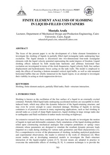
Production Engineering & Design For Development, PEDD7,Cairo, February 7 – 9, 2006Example 4: Tank with horizontal baffles.A tank with horizontal baffles is now investigated. The configuration is shown in Fig. 7. Twoidentical rigid baffles are fitted to the opposite side walls of the tank. The analysis followsdirectly from the formulation presented above.yη(x,t)Free surfaceB/2HBafflecRigid tankLxFig. 7. Rectangular tank with horizontal baffles.Figure 8 shows the liquid velocity field at the first two slosh modes throughout the tank. Thehorizontal baffles are placed at a height of 70% of the total liquid depth, measured from thetank bottom, and the combined length of the two baffles covers 60% of the tank length.Liquid motion beneath the horizontal baffles is significantly reduced.(b)Fig. 8. Liquid velocity field in a tank with horizontal baffles at the (a) first, and (b) secondslosh mode (B/L 0.6, c/H 0.7).Figure 9 shows the variation of the fundamental slosh frequency with baffle location forvarious baffle sizes. Baffles extending over longer spans and placed closer to the liquid freesurface have a greater influence on lowering the fundamental slosh frequency. The limitingcase is when the two baffles are placed at the free surface and extended horizontally to meetone another, entirely trapping the liquid, in which case the liquid behaves like a rigid body asif it were frozen.801
Production Engineering & Design For Development, PEDD7,Cairo, February 7 – 9, 2006Fig. 9. Fundamental slosh frequency versus baffle location for various baffle sizes. (L 30 m, H 15m).Example 5: Arbitrary excitation.In this example, the tank is subjected to an arbitrary input excitation, and a comparison of thetank behavior for various baffle configurations is made. The chosen input base motion is a‘relaxed’ step input, in which the tank displacement during rise time is given by:wI (t ) wIII (t ) Ws2 πt 1 cos tr (22)where Ws and tr denote the steady-state displacement and rise time, respectively. Figure 10shows the time response of the resultant hydrodynamic forces acting on the tank walls for thecases of an unbaffled tank, a tank provided with a vertical baffle, and one with horizontalbaffles, all evaluated for Ws 1m and tr 5s. For the particular configurations chosen, it isshown that significant reduction (almost 50%) in the induced hydrodynamic forces can beattained by introducing horizontal baffles in the tank design. A 30% reduction in forces isachieved with a single vertical baffle.Fig. 10. Resultant hydrodynamic force acting on tank walls (L 30 m, H 15m, Ws 1m, tr 5s)., unbaffled tank;, tank with a vertical baffle (l/L 0.5, h/H 0.6);horizontal baffles (B/L 0.6, c/H 0.7).802, tank with
Production Engineering & Design For Development, PEDD7,Cairo, February 7 – 9, 20065. CONCLUSIONSThis paper presented a finite element formulation of the fluid—structure interaction problemto study the sloshing behavior of liquids in rigid rectangular tanks. Liquid sloshing effectsinduced by horizontal base excitation are investigated in terms of the slosh frequencies, liquidvelocity field, free surface displacement and hydrodynamic forces acting on the tank walls.Results of the present work compare quite favorably with established predictions reported inthe literature. The model is employed to study the effects of inserting both vertical andhorizontal rigid baffles within the liquid domain on the slosh frequencies and free surfacemotion during forced vibration, in an attempt to investigate their viability in acting as sloshsuppression devices. Numerical simulations indicate that significant reduction in thehydrodynamic forces is achieved for baffled tanks subjected to various external excitationschemes.REFERENCES1. Housner, G.W., “Dynamic Pressures on Accelerated Fluid Containers,” Bulletin of theSeismological Society of America, Vol. 47, pp. 15-35, 1957.2. Abramson, H.N., The Dynamic Behavior of Liquids in Moving Containers, NASA SP106, Washington, D.C., 1966, updated by Dodge, F.T., Southwest Research Institute, 2000.3. Frandsen, J.B., “Sloshing Motions in Excited Tanks,” Journal of Computational Physics,Vol. 196, Issue 1, 53-87, 2004.4. Wu, G.X., Ma, Q.W. and Taylor, R.E., “Numerical Simulation of Sloshing Waves in a3D Tank based on a Finite Element Method,” Applied Ocean Research, 20, 337-355, 1998.5. Pal, N.C., Bhattacharyya, S.K. and Sinha, P.K., “ Non-linear Coupled Slosh Dynamicsof Liquid-filled Laminated Composite Containers: A Two Dimensional Finite ElementApproach,” Journal of Sound and Vibration, 261(4), 729-749, 2003.6. Çelebi, M.S. and Akyildiz, H., “Nonlinear Modelling of Liquid Sloshing in a MovingRectangular Tank,” Ocean Engineering, Vol. 29, Issue 12, 1527-1553, 2002.7. Frandsen, J.B. and Borthwick, A.G.L., “Free and Forced Sloshing Motions in a 2-DNumerical Wave Tank,” Proceedings of OMAE’02: The 21st International Conference onOffshore Mechanics and Arctic Engineering, June 23-28, Oslo, Norway, 2002.8. Propellant Slosh Loads, NASA SP-8009, August 1968.9. Slosh Suppression, NASA SP-8031, May 1969.10. Warnitchai, P. and Pinkaew, T., “Modelling of Liquid Sloshing in Rectangular Tankswith Flow-Dampening Devices,” Engineering Structures, Vol. 20, No. 7, 593-600, 1998.11. Cho, J.R. and Lee, H.W., “Numerical Study on Liquid Sloshing in Baffled Tank byNonlinear Finite Element Method,” Computer Methods in Applied Mechanics andEngineering, Vol. 193, 2581-2598, 2004.12. Cho, J.R., Lee, H.W. and Ha, S.Y., “Finite Element Analysis of Resonant SloshingResponse in 2-D Baffled Tank,” Journal of Sound and Vibration, in press.13. Choun, Y-S., and Yun, C-B., “Sloshing Characteristics in Rectangular Tanks with aSubmerged Block,” Computers and Structures, Vol. 61, No. 3, pp. 401-413, 1996.14. Biswal, K.C., Bhattacharyya, S.K. and Sinha, P.K., “Dynamic Characteristics of LiquidFilled Rectangular Tank with Baffles,” The Institution of Engineers (India), Vol. 84, 145148, 2003.15. Evans, D.V. and McIver, P., “Resonant Frequencies in a Container with a VerticalBaffle,” Journal of Fluid Mechanics, Vol. 175, 295-307, 1987.16. Haroun, M.A. and Housner, G.W., “Dynamic Characteristics of Liquid Storage Tanks,”Journal of Engineering Mechanics, ASCE, Vol. 108, No. EM5, 783-800, 1982.803
tank—surface-wave system, and forms the basis of the finite element model described in the following section. 3. FINITE ELEMENT FORMULATION The finite element model developed in this work relies upon discretizing the liquid domain into four-noded rectangular elements, with the liquid velocity potential being the only degree of freedom at each .