Transcription
CME506R, CME656R & CME806R Service PartsThis parts list contains the service part numbers for 3 basic Electrical Components Common to All Machinesmodels, plus 4 different electrical configurations. It Inlet water valvecontains service parts for all series machines. The seriesdifferences include: System controller A - first production Water sensorB - not used Discharge line sensorC - New front panel and side panels Bin controlsD - New top panel and PTCR Water level sensorE - New side panels and CME506R expansion Hi pressure cut outvalve changeUnique Electrical ComponentsThe complete model number will be needed to identify the Compressor and related starting componentscorrect part. Contactor (single / three phase)Unique parts include: cabinet, electrical and refrigeration. Fan motorElectrical Codes are located at the end of the modelnumber (voltage/hertz/phase): Water pump Transformer -1 is 115/60/1 Hot gas valve -32 is 208-230/60/1 -3 is 208-230/60/3 -6 is 250/50/1Table of ContentsCabinet. . . . . . . . . . . . . . . . . . . . . . . . . . . . . . . . . . . . . . . . . . . . . .page 2Interior Structure and Controls . . . . . . . . . . . . . . . . . . . . . . . . . . . . . . . . . .page 3CME506 Refrigeration . . . . . . . . . . . . . . . . . . . . . . . . . . . . . . . . . . . . . . .page 4CME506 E Series Refrigeration . . . . . . . . . . . . . . . . . . . . . . . . . . . . . . . . . .page 5CME656 Refrigeration . . . . . . . . . . . . . . . . . . . . . . . . . . . . . . . . . . . . . . .page 6CME806 Refrigeration . . . . . . . . . . . . . . . . . . . . . . . . . . . . . . . . . . . . . . .page 7Receiver . . . . . . . . . . . . . . . . . . . . . . . . . . . . . . . . . . . . . . . . . . . . . .page 8Water System Components . . . . . . . . . . . . . . . . . . . . . . . . . . . . . . . . . . . .page 9Compressors and Electrical Components. . . . . . . . . . . . . . . . . . . . . . . . . . . .page 10. . . . . . . . . . . . . . . . . . . . . . . . . . . . . . . . . . . . .page 11Remote Condenser . . . . . . . . . . . . . . . . . . . . . . . . . . . . . . . . . . . . . . . .page 12Wiring Diagrams . . . . . . . . . . . . . . . . . . . . . . . . . . . . . . . . . . . . . . . . . .page 13HTB555 Ice Storage BinMarch 2002Page 1
CME506R, CME656R & CME806R Service DescriptionRight side panel, grey enamel without louversA - D series right side panel, stainless steel without louversE Series right side panelTop insulationC series Front panel kit, gray plastic, includes trim strip & emblemsStrike (for C model panel, SS and plastic)Front panel kit, gray plastic, includes item 10a (for A series)C or D series Front panel kit, stainless steel, includes trim strip & emblemsFront panel kit, stainless steel (for A models)Emblem for ss panel (Scotsman); 03-0271-00 is the speed nut for emblemEmblem for C to E series front panel, (CM3)Screw for trim strip (for C or D or E series)Sheet metal screw for plastic front panel (for A series)Sheet metal screw for ss front panelPanel bumper/hole plugSheet metal screw for A - C seriesMachine screw for D seriesLeft side panel, grey enamel without louvers A - D series onlyLeft side panel, stainless steel without louvers A - D series onlyE Series Left side panelTop panel, grey enamel, order item 2 alsoTop panel, stainless steel, order item 2 alsoTop panel, plastic, original with D series, fits all and includes item 2Evaporator cover, use began Feb. 1997. For A and B seriesEvap cover insulation for above coverEvaporator cover w/ins for C - E seriesSpeed nut for panel screws1202-3794-01Trim strip.Catch03-1731-02Push nut for trim stripMarch 2002Page 2
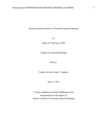
CME506R, CME656R & CME806R Service Parts26Interior Structure & Controls9Note: Item 25 mounts to Item 1.Item 1 must have rectangular7 tabs. All units after 9/96 weremfg. with rectangular tabs.252010211811911122772324221315 rtNumberDescription02-3409-21Bin Control Sensor (set)02-3337-01Cube deflector02-3339-01Stand pipe02-3610-01Stand pipe adjusting nut02-3360-01Reservoir washer13-0617-56O-ring02-3338-01Drain tube & fittings03-1404-18ScrewA36298-001Left side channel03-1404-05ScrewA36297-001Right side channel13-0906-01Plastic Inlet water tube, 21"not used after Sept. 199603-1645-01Screw03-1691-01Nylon screw02-3340-01Reservoir cover12-2548-01Inlet water valve13-0674-02Tubing, 9" req., order 1 unit02-3443-01Water inlet fitting for hose16-1020-01Water fitting for copper02-0179-05Clamp for hose13-0903-01Bumper for side panels16-0997-01Inlet water fitting for hose16-1019-01Inlet water fitting for 2202-3657-012627A36460-001A35959-00124March 2002Page 34DescriptionMounting flangeSystem controller, fits allHi Voltage harness A - CHi voltage harness - D seriesLo voltage harness A - CLo voltag harness, D seriesCascading shield, use began2/97.Back panel assyHi voltage box cover
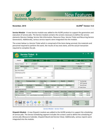
CME506R, CME656R & CME806R Service PartsCME506R A - D Series Refrigeration System161211151314312109786See Page ptionReceiverDryerLiquid line valveEvaporatorTXV1611-0422-24Insulation for TXV1716-1063-01Pump down pressure switchDistributor and tubesCrankcase heaterDischarge line temperature sensor, includeswater temp sensor & clipSensor clipHi pressure cut out switchAccumulatorAccess valvePort capStem capLiquid line fittingDischarge line fittingHot gas valve completeHot gas valve coilMarch 2002Page 44Discharge pressure control valveHot gas valve strainer, not shown
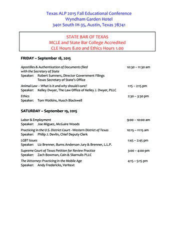
CME506R, CME656R & CME806R Service PartsCME506R E Series Refrigeration System11181910 17115127913231612614SeePage mPartNumber ryer1816-1071-01Liquid line valve19A37247-001EvaporatorTXV - only for E seriesInsulation for TXVPump down pressure switchTeeCrankcase heaterDischarge line temperature sensor, includeswater temp sensor & clipSensor clipHi pressure cut out switchAccumulatorAccess valvePort capStem capLiquid line fittingDischarge line fittingHot gas valve completeHot gas valve coilMarch 2002Page 5DescriptionDischarge pressure control valveHot gas valve strainerCheck valveBy-pass tubing
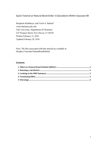
CME506R, CME656R & CME806R Service PartsCME656R Refrigeraiton System161112151314312109See Page 16-0843-02812-2308-01902-3410-21water temp sensor & clip03-1711-011011-0501-2211no ceiverDryerLiquid line valveEvaporatorTXV1611-0422-24Insulation for TXV1716-1063-01Pump down pressure switchDistributor and tubesCrankcase heaterDischarge line temperature sensor, includesSensor clipHi pressure cut out switchSuction lineAccess valvePort capStem capLiquid line fittingDischarge line fittingHot gas valve completeHot gas valve coilMarch 2002Page 64Discharge pressure controlHot gas valve strainer,not shownvalve
CME506R, CME656R & CME806R Service PartsCME806R Refrigeraiton System161112151314312109See Page 711-0111-0501-22no ReceiverDryerLiquid line valveEvaporatorTXVInsulation for TXVPump down pressure switchDistributor and tubesCrankcase heaterDischarge line temperature sensor, includes water temp sensor & clipSensor clipHi pressure cut out switchSuction lineAccess valvePort capStem capLiquid line fittingDischarge line fittingHot gas valve completeHot gas valve coilDischarge pressure control valveMarch 2002Page 74
CME506R, CME656R & CME806R Service rBracketScrewScrewBack coverBracketScrewMarch 2002Page 8
CME506R, CME656R & CME806R Service PartsWater System 98-0102-3336-0102-3410-21no er distributorCME506-1 pump (115/60 Hz)CME656 or CME506-6 or CME806 (203-230/50-60 Hz) pumpTubing grommetWater distributor tubeWater temperature sensorincludes disch. temp. sensorCable tieInlet TeeRubber plugFloatFloat stem grey, non adjustable after 2/97Float sensorFront pump bracket for 12-2586 type pumpRear pump bracket for 12-2586 type pumpHarnessMarch 2002Page 98
CME506R, CME656R & CME806R Service PartsCompressors and Electrical ComponentsStart Capacitor,A - C SeriesRelay, A - CSeriesCompressorBoltPTCR, DSeries OnlyWasherTransformerGrommet, SleeveRun 3-2518-8813-2718-8749-22*18-8749-27PTCR** 8835-0118-8835-0118-8835-01Start Relay**18-1903-5018-1903-2918-1903-33not 18-1901-0318-1901-4318-1901-15not 902-4518-1902-3018-1902-53not 001A37217-001A37217-001March 2002Page 10
CME506R, CME656R & CME806R Service PartsHTB555 Ice Storage 011121314Not 08-01DescriptionSpacerHingeShoulder screwE-RingGasket, order 9 unitsDoor frame - GreyDoor gasket, order 5 unitsDoor - GreyThumb screwCanopyBaffleDrain topO-RingDrain bottom05-0586-0102-0540-00Drain elbowScoopBinLiner(ref)121413Drain Fitting DetailMarch 2002Page 11
CME506R, CME656R & CME806R Service Parts123456ITEMNUMBER 02-3231-0302-3231-02PARTDESCRIPTIONFan guardFan bladeFan motor ERC101Fan motor ERC201, ERC402Quick connect, dischargeQuick connect, liquidLeg kit for ERC101, 201Leg kit for ERC402Discharge lineLiquid lineMarch 2002Page 12
CME506R, CME656R & CME806R Service PartsD Series, Single Phase Schematic DiagramN ( 115/ 60/ 1 UNITS)L2 ( 230/50-60/1UNITS)L1CRANKCASE HEATERLI NETRANSFORMER24VHOT GAS VALVEWATER VALVECONTACTORCOILHIGHLOWPRESSURE PRESSURECONTROL CONTROLLIQUID LINESOLENOIDELECTRONIC CONTROLSUMP BINTEMP. FULLX- MI RWATERPUMPPTCRRUNCAP.COMPRESSORREMOTE CONDENSER FANMarch 2002Page 13
CME506R, CME656R & CME806R Service PartsD Series, CME506R Wiring DiagramUSE COPPER CONDUCTORS ONLY17-2748-011 DASHED LINES INDICATE FIELD WIRING WHICH MUST BEINSTALLED IN ACCORDANCE WITH THE NATIONAL ELECTRICALL.L.MOTCODE AND ALL STATE AND LOCAL CODES.PUMPWATERHOT GASSOLENOIDO2 WIRE COLOR FOR 115/60/1 UNITS: BLACKORSOLENOIDWIRE COLOR FOR 230/50/1 UNITS: BLUESOLENOID3 WIRE COLOR FOR 115/60/1 UNITS: WHITEWIRE COLOR FOR 230/50/1 UNITS: BROWNBNWBUCAUTION: PTCR WILL BE HOT.BKBUCOMPRESSOR MAY NOT START IFOPTCR IS NOT ALLOWED TO COOL.PTCROY/ WL1B K/ WSUMP TEMP.SENSORBKL21 2 3 4 5 6 78DI SCHARGETEMP.SENSOR1 2 3 49L I NEL OAD1 2 3 4 5W/ RV5VTRANSFORMER1 2 31 2 33YRELECTRONICCONTROL23BUBU2CRANKCASE HEATERJUNCTIONBOX1FUSI TEYCOMMUNICATIONSGROUNDPORTI NDINGSTART WI NDING RUNW1 2 3 4 5BKBKBK432 1CAPW7BIN FULLBIN FULLRECIEVERRUNT2CONTACTOR6TRANSMITTERR/ WT1SCREWWATERLEVELEARTH YTHIS UNIT MUSTREMOTEPOWER SUPPLYCONDENSERSEE NAMEPLATE FORBE GROUNDED.HI PRESSURECONTROLLO PRESSURECONTROLPROPER VOLTAGE REQUIREMENTSFANCAUTION:MORE THAN ONE DI SCONNECT MEANS MAY BEAND MAXIMUM FUSE SIZEREQUI RED TO DI SCONNECT ALL POWER TO THI S UNI T.March 2002Page 14
CME506R, CME656R & CME806R Service PartsD Series, CME656R and CME806R Single Phase Wiring DiagramUSE COPPER CONDUCTORS ONLY17-2751-011 DASHED LINES INDICATE FIELD WIRING WHICH MUST BE( AC ONL Y)WATERINSTALLED IN ACCORDANCE WITH THE NATIONAL ELECTRICALHOT GASMOTPUMPMOTFANGRAYCODE AND ALL STATE AND LOCAL CODES.OSOLENOIDSOLENOIDWBNWBULBC A U T I O N :P T C RBKC O MP R E S S O RBKP T C RWIMA YL LB EN O TH O T .S T A R TI FOI SN O TA L L O WE DT OC O O L .PTCROOW/ Y1 2 3 4 5 6 781 2 3 49T2W7W/ RLI NELOADW/ RTRANSFORMERE LECTRONI CBK1 2 3CONTROL1 2 31 2 3 4 5YV31 2 3 4 5RUNCAP5432 1BIN FULLRECIEVERL2CONTACTOR6BIN FULLTRANSMITTERT1BKSUMP TEMP.SENSORDI SCHARGETEMP.SENSORL1BKPROTECTORINTERNALB K/ W2JUNCTIONBOX1YYCOMMUNICATIONSGROUNDSCREWHI PRESSUREPORTTERMINAL BOXRC1BKR3CONTROLEARTH GROUND(WC ONLY)WATERLEVELSENSORP OWE R S UPP LYS EE NAMEPL ATE FORP ROP ER VOL TAGE REQUI RE MENTSA ND MAX I MUM F USE SI ZETHIS UNIT MUSTCAUTION:BE GROUNDED.MOR E TH AN ONE D I S CONN EC T ME AN S MA Y BER EQUI RE D TO D I S CONN EC T AL L POWE R TO T HI S UN I T .March 2002Page 15WCOMPRESSORS2R
CME506R, CME656R & CME806R Service PartsD Series, Three Phase Schematic DiagramL1L2CRANKCASE HEA T ERLINETRANSFORMER24VHOT G AS VA LVEWATER VALVECONTACTOR COILHIGHLOWPRESSURE PRESSURECONTROL CONTROLLIQUID LINESOLENOIDELECTRONIC CONTROLSUMP BINTEMP. FULLX- MI RWATERPUMPCONTACTORCONTACTORCOMPRESSORREMOTE CONDENSER FANMarch 2002Page 16L3
CME506R, CME656R & CME806R Service PartsD Series, Three Phase Wiring Diagram17-2758-01USE COPPER CONDUCTORS ONLYL.L.O1 DASHED LINES INDICATE FIELD WIRING WHICH MUST BESOLENOIDMOTPUMPWATERINSTALLED IN ACCORDANCE WITH THE NATIONAL ELECTRICALHOT GASGRAYSOLENOIDCODE AND ALL STATE AND LOCAL CODES.OSOLENOIDBNWBUOBKLBOOL1BKSUMP TEMP.SENSORT1BKL2T2L3T3O1 2 3 4 5 6 78DI SCHARGETEMP.SENSOR1 2 3 49CONTACTOR7LOADVTRANSFORMERBKBKR1 2 3BIN FULLTRANSMITTERV541 2 31 2 3 4 56LI NEW3RRELECTRONICCONTROLBKBKBKBUBU1 2 3 4 5CRANKCASE HEATER32 1BIN OXC1BKR3EARTH GROUNDYCOMPRESSORTHIS UNIT MUSTW1YREMOTECONDENSERBE GROUNDED.POWER SUPPLYHI PRESSURECONTROLLO PRESSURECONTROLSEE NAMEPLATE FORPROPER VOLTAGE REQUIREMENTSAND MAXIMUM FUSE SIZEMarch 2002Page 17FANCAUTION:MORE THAN ONE DI SCONNECT MEANS MAY BEREQUI RED TO DI SCONNECT ALL POWER TO THI S UNI T.
CME506R, CME656R & CME806R Service PartsSingle Phase Schematic Diagram, A - C SeriesMarch 2002Page 18
CME506R, CME656R & CME806R Service PartsA -C Series Single Phase Wiring DiagramMarch 2002Page 19
CME506R, CME656R & CME806R Service PartsA -C Series Three Phase Schematic DiagramMarch 2002Page 20
CME506R, CME656R & CME806R Service PartsA - C Series Three Phase Wiring DiagramMarch 2002Page 21
CME506R E Series Refrigeration System Item Part Number Number Description 1 16-0761-01 Receiver 2 02-3319-02 Dryer 3 12-2471-23 Liquid line valve 4 A36734-020 Evaporator