Transcription
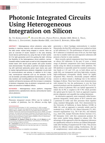
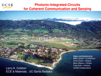
Silicon Photonic Integrated CircuitsRoger HelkeyJohn BowersUniversity of California, Santa BarbaraArt Gossard, Jonathan Klamkin, Dan Blumenthal, Minjoo Larry Lee1, Kei May Lau2,Yuya Shoji3, Tetsuya Mizumoto3, Paul Morton4, Tin Komljenovic, N. Volet,Paolo Pintus, Xue Huang, Daehwan Jung2, Shangjian Zhang, Chong Zhang,Jared Hulme, Alan Liu, Mike Davenport, Justin Norman, Duanni Huang, Alex Spott,Eric J. Stanton, Jon Peters, Sandra Skendzic, Charles Merritt5, William Bewley5,Igor Vurgaftman5, Jerry Meyer5, Jeremy Kirch6, Luke Mawst6, Dan Botez61 YaleUniversity3 Hong Kong University of Science and Technology5 Naval Research Laboratory12 TokyoInstitute of Technology4 Morton Photonics6 University of WisconsinUCSB Research supported byONR, Mike Haney ARPA-E,Conway, Lutwak at DARPA MTO, Aurrion, Keysight
What is Silicon Photonics? Making photonic integrated circuits on Silicon using CMOSprocess technology in a CMOS fab Improved performance and better process control Wafer scale testing Low cost packaging Scaling to 1 Tb/sHigh bandwidthLong distancesNoise ImmunityHigh volumeLow costHigh Scalability2
Advantage - Waveguide lossInP / GaAsOptimizedSiSiBauters et al. Optics Express (2011)
Silicon Photonics PapersFirst Hybrid Silicon PIC with 200 photonic elements (2014)Hybrid Silicon Modulator with 74 GHz BW (2012)First Hybrid Silicon DFB (2008)First Hybrid Silicon PIC (2007)First Hybrid Silicon Photodiode (2007)First Hybrid Silicon Amplifier (2006)First Hybrid Silicon Laser (2005)Soref and Bennet (1987)
Si Photonics - Heterogeneous Integration CMOS compatible processEfficient light coupling with Si WGComponent developmentPIC integration with 400 elementsHigh gain SOA on SiDavenport, CLEO SM4G.3Isolators/Circulator on SiHuang, CLEO SM3E.14.8 μm QCL laser on SiSpott, CLEO STh3L.4Low-Loss AWG in VisStanton, CLEO SM1F.12.56 Tbps NoCZhang, CLEO JTh4C.45
Optical Amplifier on Si Scale of Si PICs rapidly increasing Overcome insertion loss, splitter loss Increase power and equalize opticalpower in multi-channel devices Recover signal power before detectionHeterogeneous amplifier sectionContact metal2 mmPassive Si waveguideHeterogeneous transitionDavenport, Skendzic, Volet, Bowers CLEO 20166
Amplifier on Si - Process flowa) Silicon etchingf): Via andprobe metalb): III-V bondinge): Hydrogenimplantc): III-V etchingd) Deposition ofelectrodesDavenport, Skendzic, Volet, Bowers CLEO 20167
Amplifier on Si - DimensionsDavenport, Skendzic, Volet, Bowers CLEO 20168
Amplifier on Si - Heterogeneous TransitionPassive SiwaveguideP-mesataperSi taperActiveregion taperN-InP taperActive Si/InPwaveguideDavenport, Skendzic, Volet, Bowers CLEO 20169
Amplifier on Si – Transition ReflectionPassivesiliconwaveguideHeterogeneousgain sectionPolishedfacet(R 0.28)Polishedfacet(R 0.32) Reflection determinedby fitting model to ASEspectrum Rtaper r -46 dBDavenport, Skendzic, Volet, Bowers CLEO 201610
Amplifier on Si - Performance High gain: 26 dB from 0.95 μm waveguide device High power: 16 dBm from 1.4 μm waveguide device Large 3dB BW: 66 nmDavenport, Skendzic, Volet, Bowers CLEO 201611
Microring Isolator - Nonreciprocity Optical isolators allow light transmission in only one direction Necessary in many applications to block undesired feedback for lasers Requires nonreciprocal phenomenon to break spatial-temporalsymmetryNonreciprocal phase shift (NRPS) Forward and backwardspropagating modes in amagneto-optic waveguidehave different propagationconstant (b). Nonreciprocal phase shiftUnbalanced MZIin a phase-sensitivestructure can result inoptical isolation for the TM Y. Shoji, T. Mizumoto, et al.,Opt. Express (2008)mode.MicroringM.C. Tien, J. Bowers, et al.,Opt. Express (2011)Huang, Pintus, Zhang, Shoji, Mizumoto, Morton, Bowers OFC 201612
Microring Isolator - Design Magneto-optic material Ce:YIG wafer bonded to all-pass silicon microring CW and CCW modes are different, causing a resonance splitTransmittedPower𝜆Resonance wavelength split Resonance wavelength splitdependent on waveguide geometry Isolation depends on extinction ratioand coupling coefficientIntrinsicCW mode(forward)CCW mode(backward)Operating wavelengthHuang, Pintus, Zhang, Shoji, Mizumoto, Morton, Bowers OFC 201613
Microring isolator - Results 32 dB of isolation with recordlow 2.3 dB excess lossachieved with small footprint(35 mm radius).Demonstrated isolators on siliconConsumes 10 mW of power,and no permanent magnet isneeded Current controlled magneticfield and Joule heating providestuning over0.6 nm with 20 dB of isolation.This WorkHuang, Pintus, Zhang, Shoji, Mizumoto, Morton, Bowers OFC 2016
Microring Circulator Light circulates depending onwhether it is coupled into the CW(off-resonance) or the CCW (onresonance) mode in the ring.1- 22- 1Circulation Direction1243Huang, Pintus, Zhang, Shoji, Mizumoto, Morton, Bowers IPC 201615
Microring Circulator - ResultsExperimentalSimulated Isolation Ratio S21 2/ S12 2 11dBHuang, Pintus, Zhang, Shoji, Mizumoto, Morton, Bowers IPC 20167
AWG - Spectral Beam CombiningVisible to Mid-IR Multiplexing data Spectroscopy Scaling powerand brightness Ultra low-lossarrayedwaveguidegratings (AWGs)are importantStanton, Spott, Davenport, Volet, Bowers CLEO 201617
Previously demonstrated low-loss AWGsLow-loss AWGs with 1 dB insertion loss in near-IR:– D. Dai et al., Opt. Express 19, (2011).– J. F. Bauters et al., Appl. Phys. A 116, (2014).– A. Sugita et al., IEEE Photon. Technol. Lett. 12, (2000).Low-loss AWGs near-visible spectrum are difficult to makeRecent demonstration of 1.2 dB insertion loss at 900 nm– D. Martens et al., IEEE Photon. Technol. Lett. 27, (2015). Wavelength target 760 nm– Scattering loss scales by 1/λ4– 1.2 dB @ 900 nm - 1.6-2 dB @ 760 nm(scattering loss contribution 1/3rd-2/3rd)Stanton, Spott, Davenport, Volet, Bowers CLEO 201618
Challenges for low-loss AWGs Waveguide propagation loss Scattering loss scales by 1/λ4 High aspect ratio waveguides todecrease interfacial scattering Minimize material impuritiesE(z) E0e-αz Transition loss from straight tobends Use adiabatic transitions Phase and amplitude errors inarrayed waveguides Mask optimization - process Minimize mask errorsStanton, Spott, Davenport, Volet, Bowers CLEO 201619
AWG - Mask Writing Address-UnitUsing small address unit for the mask writing is critical in near-visibleregion50 nm address unit Pseudo-random length error 150 nm5 nm address unit Pseudo-random length error 15 nmStanton, Spott, Davenport, Volet, Bowers CLEO 201620
Insertion loss analysis Center channel insertionloss 0.5 dB(Record – 760 nm) Record low crosstalk -23 dBStanton, Spott, Davenport,Volet, Bowers CLEO 201621
Mid-infrared Silicon PhotonicsMid-infrared ( 2-20 µm) photonics Spectral Beam CombiningGas sensingChemical bond spectroscopyBiological sensingEnvironmental analysisRemote sensingNonlinear optics- Reduced two photon absorptionin silicon past 1.8 µmSpott, Peters, Davenport, Stanton, Merritt,Bewley, Vurgaftman, Meyer, Kirch,Mawst, Botez, Bowers CLEO 2016Methane trapped in ice, National GeographicPower plant emissions, National Geographic22
4.8 µm Quantum Cascade Laser 30-stage QCL material adapted for heterogeneous integration4-8 µm-wide III-V mesas with 1.5-3.5 µm-wide Si waveguides3 mm-long hybrid III-V/Si active region45 µm-long III-V tapersλ/4-shifted 1st order distributed feedback (DFB) grating in siliconwaveguide under active regionSpott, Peters, Davenport, Stanton, Merritt, Bewley, Vurgaftman,Meyer, Kirch, Mawst, Botez, Bowers CLEO 201623
4.8 µm Laser FabricationBondRemove substrateDry etch upper cladWet etch activeDeposit lower metalDry etch lower cladDeposit PECVD SiNDry etch viasDeposit upper metalDeposit probe metal(3)n-InPcladding(8)(4)(5)(9) waveguidelapping3PO3 III-V4dry2etch2/DI4/H2/Arand selective wet etch24
4.8 µm DFB (with Taper) Low threshold current densities Low differential efficiency Highest output power 11 mW/facetSpott, Peters, Davenport, Stanton, Merritt, Bewley, Vurgaftman,Meyer, Kirch, Mawst, Botez, Bowers CLEO 201625
4.8 µm DFB (Taper Removed) Heterogeneous taper limiting performance?– Polished off one side for further testing– 211 mW output power (pulsed) Up to 100 C pulsed operation Extracted T0:- 𝐽𝑡ℎ 𝐽0 e𝑇/𝑇0 𝑇0 199 𝐾Spott, Peters, Davenport, Stanton, Merritt, Bewley, Vurgaftman,Meyer, Kirch, Mawst, Botez, Bowers CLEO 201626
Evolution of Multicore Processors1) Number oftransistors israpidly increasing2) clock rates arenot increasing3) Powerconsumption isconstrained4) Rapidlyincreasingnumber of coresSource: C. Batten27
Waveguide Optics – Available Width Get enough optical channelsoff the edge of the chip? For waveguides around chipperimeter need:– Very dense waveguides, or– High clock speeds andWDMDavid Miller IEEE Photonics Conf 201328
Photonic Moore’s Law Integrated reconfigurable transceiver network for chip-levelinterconnectionNumber of Elements / PIC– Over 400 elements on chip– Total 2.56 Tbps data capacity103This earChong Zhang, S. Zhang, J. Peters, J. E. Bowers CLEO 201629
Reconfigurable NoC (Network-on-Chip) BUS-ring network on chip with flexible configuration WDM signal routing enabled by broadband switch fabric Reconfigurable modesChong Zhang, Zhang, J. Peters, J. E. Bowers CLEO 201630
Reconfigurable NOC - Layout and FabricationBragg grating on Si1 mmDFB taper10 mmPD mesa48 DFB, 93 EAM, 67 PD, 17 AWG 20 mmChong Zhang, S. Zhang, J. Peters, J. E. Bowers CLEO 201631
Reconfigurable NOC - Link PerformanceSmall Signal Response (dB) A 6-dB bandwidth of 24 GHz was measured for the EAM-PD link. Data rate of 40 Gbps per channel, showing a potential large capacityof the transceiver array, with 320 (8 40) Gbps per transceiver node,and 2.56 Tbps (8 320 Gbps) for the whole photonic circuit.28 Gbps30 Gbps35 Gbps40 Gbps0-6 dB-5-10DataFitting-15-20010203040Frequency (GHz)Chong Zhang, S. Zhang, J. Peters, J. E. Bowers CLEO 201632
Low-Cost Lasers - Missing PieceSi : Indirect bandgap, low internal quantum efficiency (10-6) Hybrid integration Monolithic integration Size and cost limitation Low cost and high yieldGhent Univ. 2007UCSB, 2006UCSB 2016University College London. 201633
Issues with Epitaxial Lasers on Si Offcut Si substrates: Not compatible with standard CMOS foundry process Ge buffer layers: Absorptive and relatively thick,preclude potential incorporation in the SOI technology Low energy consumption: Required for high integration density 1.3 μm Qdot lasers grown on GaP/GaAs buffer lasers Reduced back-reflection sensitivity of Quantum-Dot lasers– Liu, Peters, Huang, Jung, Komljenovic, Davenport,Norman, Lee, Gossard, Bowers ISLC 201634
Lasers on GaP Buffer - Epi Design300 nm GaAs:Be (2 1019 cm-3)50 nm 36 0% AlxGa(1-x)As:Be (1 1019 cm-3)1.4 μm Al0.36Ga0.6As:Be cladding (7 1017 cm-3)20 nm 20 36% AlxGa(1-x)As:Be (4 1017 cm-3)30 nm Al0.2Ga0.8As:Be SCH (4 1017 cm-3)12.5 nm UID GaAs37.5 nm p/UID GaAs7x50 nm GaAs:UID30 nm Al0.2Ga0.8As:Si SCH (2 1017 cm-3)20 nm 36 20% AlxGa(1-x)As:Si (2 1017 cm-3)1.4 μm Al0.36Ga0.6As:Si cladding (2 1017 cm-3)50 nm 0 36% AlxGa(1-x)As:Si (1 1018 cm-3)1000 nm GaAs:Si (2 1018 cm-3)2300nm GaAs:si (1-5 1018 cm-3)45 nm GaPSi (001)10 nm GaAs:UID10 nm GaAs:Be (5 1017 cm-3)17.5 nm GaAs:UIDUCSB10 nm GaAs:UID10 nm GaAs:Be (5 1017 cm-3)17.5 nm GaAs:UID10 nm GaAs:UIDYale UniversityNAsPIII-V GmbHLiu, Peters, Norman, Huang, Jung, Lee, Gossard, Bowers ICMBE 201635
QD Laser - High Temp Lasing CW lasing to 90 C Characteristic temperature, T0– 42K 40-90 C Ith 30 mA (3-4 µm ridge laser)Liu, Peters, Huang, Jung, Komljenovic, Davenport, Norman, Lee, Gossard, Bowers ISLC 201636
Sensitivity to reflections Unintentional reflections can disturb lasing stability (increasedlinewidth and intensity noise) Isolators typically used to prevent this, but adds and footprint,on-chip isolators would potentially add loss Desirable to avoid isolators altogetherIsolatorLiu, Peters, Huang, Jung, Komljenovic, Davenport, Norman, Lee, Gossard, Bowers ISLC 201637
Sensitivity to reflections - Theory Laser stability with feedback depends on 1:– Damping of relaxation oscillation (higher in QD lasers)– 1/α2 (α may be lower in QD lasers)1J. Helms and K. Petermann,IEEE J. Quant. Electron. 833 (1990)damping factorimprovement 10 , Peters, Huang, Jung, Komljenovic, Davenport, Norman, Lee, Gossard, Bowers ISLC 201638
Sensitivity to reflections - Measurement Characterization of sensitivity to optical reflections– Laser output split with a 50:50 coupler with half going to spectrumanalyzer for RIN measurement, other half reflected back to laser– Polarization control with in-line Faraday rotator plus Faraday mirror External cavity length: 15 meters– Feedback level is defined as ratio of power levels in forward andback monitor PDsVOADC biasLaser99:150:50Back PDISO àFaradayrotatorFaradayMirrorHP 70810BLightwaveSectionFwd PDLiu, Peters, Huang, Jung, Komljenovic, Davenport, Norman, Lee, Gossard, Bowers ISLC 201639
Sensitivity to reflections: QW vs QDot For QW laser, low frequency RIN increases by up to 30 dB vs feedbackLiu, Peters, Huang, Jung, Komljenovic, Davenport, Norman, Lee, Gossard, Bowers ISLC 201640
Sensitivity to reflections: QW vs QDot For QW laser, low frequency RIN increases by up to 30 dB vs feedback For QD laser, increase in RIN is only 10 dB41Liu, Peters, Huang, Jung, Komljenovic, Davenport, Norman, Lee, Gossard, Bowers ISLC 2016
Sensitivity to reflections: QW vs QDot For QW laser, low frequency RIN increases by up to 30 dB vs feedback For QD laser, increase in RIN is only 10 dB 20 dB higher feedback for RIN increase to -135 dBc/Hz in QDs vs QWsLiu, Peters, Huang, Jung, Komljenovic, Davenport, Norman, Lee, Gossard, Bowers ISLC 201642
Summary I Optical amplifiers on Si (1550 nm)– High gain: 26 dB (0.95 μm waveguide device)– High power: 16 dBm (1.4 μm waveguide device)– Large optical 3dB bandwidth: 66 nm Isolator / Circulators on Si– 32 dB of isolation with record low 2.3 dB excess loss– No permanent magnet needed– 10 mW of electrical power Arrayed Waveguide Grating (AWG)– Centered near-visible (760 nm)– Record center channel insertion loss 0.5 dB (760 nm)– Record low crosstalk -23 dB (760 nm)43
Summary II 4.8 µm Quantum-Cascade Lasers on Si– 200 mW power (pulsed) from DFB laser– Pulsed operation up to 100 ºC– Threshold current densities below 1 kA/cm2 Network-On-Chip circuit on Si– Reconfigurable transceiver network for chip-level interconnect– Over 400 elements on chip, including 48 low threshold lasers– 2.56 Tbps total capacity44
Summary III First electrically-pumped CW laser monolithically grown;Si foundry compatible (001), without Ge layer– Thresholds down to 30 mA– Output power up to 110 mW– CW lasing up to 90 C Reflection sensitivity reduction QDot vs QWell 20 dB– Potential for isolator-free integration of QDot lasers45
Mid-infrared Silicon Photonics 22 Mid-infrared ( 2-20 µm) photonics Spectral Beam Combining Gas sensing Chemical bond spectroscopy Biological sensing . Lasers on GaP Buffer - Epi Design 10 nm GaAs:UID 17.5 nm GaAs:UID 10 nm GaAs:Be (5 1017 cm-3) 10 nm GaAs:UID 17.5 nm GaAs:UID 10 nm GaAs:Be (5 1017 cm-3) 10 nm GaAs:UID