Transcription
PATRAN Beginner’s GuideArul M BrittoNovember 25, 2003Contents1Introduction32How to Start a PATRAN Session2.1 Creating a New Database . .2.2 Opening New Database . . .2.3 Leaving a PATRAN Session .2.4 Resuming a Previous Session.366893Steps Involved in an analysis3.1 Units . . . . . . . . . . . . . . . . . . . . . . . . . . . . . . . . . . . . . . . . . . . . . . . .9104Create Geometry4.1 Geometry . . . . . . . . . . . . . . .4.1.1 Create Points . . . . . . . .4.1.2 Create Curves . . . . . . . .4.2 Checking and Correcting Mistakes4.2.1 Check the Points . . . . . .4.2.2 Check the Curves . . . . .4.2.3 Deleting Points and Curves4.3 Error and Warning Messages . . .4.4 Entity Labels . . . . . . . . . . . . .4.5 Checking the Surface Normal . . .10111414181820202121215Loads and Boundary Conditions5.1 Define the Load variation function . . . . . . . . . . . . . . . . . . . . . . . . . . . . . . .5.2 Loads and Boundary Conditions . . . . . . . . . . . . . . . . . . . . . . . . . . . . . . . .5.3 Load Application . . . . . . . . . . . . . . . . . . . . . . . . . . . . . . . . . . . . . . . . .232324276Define Element Properties6.1 Define Material Properties . . . . . . . . . . . . . . . . . . . . . . . . . . . . . . . . . . . .6.2 Element Properties . . . . . . . . . . . . . . . . . . . . . . . . . . . . . . . . . . . . . . . .2727297Finite Element Mesh7.1 Create Mesh Seeds . . . .7.2 Create the Mesh . . . . . .7.3 Unpost the Geometry . . .7.4 Equivalence and Optimize.3131333334Check Load/BCs8.1 Loads/BCs . . . . . . . . . . . . . . . . . . . . . . . . . . . . . . . . . . . . . . . . . . . . .8.2 Create a Load Case . . . . . . . . . . . . . . . . . . . . . . . . . . . . . . . . . . . . . . . .3536378.1.
CONTENTS9CONTENTSPerform the Analysis9.1 Submit a ABAQUS Analysis . . . . . . . . . . .9.2 Accessing the ABAQUS Results from PATRAN9.3 Post Processing . . . . . . . . . . . . . . . . . .9.4 Changing Display Parameters . . . . . . . . . .9.5 Hard Copy of Plot . . . . . . . . . . . . . . . . .9.6 Stress Fringe Plot . . . . . . . . . . . . . . . . .9.7 Using Graph (XY) Plot to plot Stress variation .9.8 To Quit from PATRAN . . . . . . . . . . . . . .37374042434446464710 Files4711 Troubleshooting4812 Frequently Asked Questions492
2 HOW TO START A PATRAN SESSION1 IntroductionPATRAN is a pre and post processing package for the finite element program ABAQUS. In additionit has the capability of finite element analysis. This manual has been prepared for users who want touse ABAQUS for finite element analysis. It also describes how once the ABAQUS analysis is run onecould carry out some post processing.This manual tells the user how to run PATRAN in the Teaching system. It also has an example problem on how to set up the data for an ABAQUS analysis using PATRAN. It explains how a ABAQUSjob can be submitted from within PATRAN and after the successful completion of the job how to usethe post processing facilities.2 How to Start a PATRAN SessionFind a suitable terminal for running PATRAN. These are the X-terminals in the main area of the DPO,the PC-based X-terminals at the East end of the DPO, and the PC-based X-terminals in the EIET Lab(Inglis building).1. Log in using your user ID and password.2. Run a window manager (example : twm& ). This is recommended. It is useful in the sense thatthe PATRAN windows can be moved around and scaled. Do not run start, fvwm or fvwm2.3. Create a subdirectory and move to it.Type mkdir patran (you need to do this only once.)Type cd patran (you need to do this for each session.)It is a good idea to re-start PATRAN in the directory in which the database resides. Even thoughit is possible to start PATRAN in any directory and then change to the directory in which thedatabase is, it is not recommended. The reason is any new files created by PATRAN (examplesession files) will be placed in the directory from which PATRAN was started.If you do not know which is your current directory then type pwd. This will list the name of thecurrent working directory.Some useful unix commands :ls -l - will list all the files in the current directory.cd - to return to your HOME directory.rm file-name - to delete a file. Replace file-name with name of file to be deleted. Example: rm bracket.datHere the subdirectory is called patran. All the PATRAN related files will be placed in this directory. When you start a session of PATRAN ensure that there is enough unused disk spaceavailable within your quota to complete the current exercise. Contact the Computer Operators ifyou require the quota to be increased.Alternatively you can work in the /tmp directory. However files created in the /tmp directoryare deleted automatically after 48 hours. Therefore if you require these files please copy them toyour home directory within that time. First check whether there is enough free disk space. If thefree disk space is less than 10 Mbytes do not use the /tmp directory.Type bdf /tmpCheck the amount available under the heading avail. This will be in KBytes.Type cd /tmpType mkdir userid . Here substitute your user-id for userid .Type cd userid to move to this directory.If you start PATRAN from here then all the files created will be placed in this directory.3
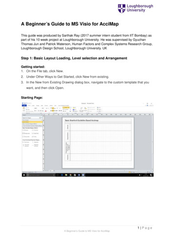
2 HOW TO START A PATRAN SESSIONRefresh graphicsReset InterruptFigure 1: Main Form4. Type patran (Note : must be in lower case)WarningWarning : Do not use the start or fvwm window manager or any of its derivatives(fvwm2). In the past some problems have been encountered while running PATRAN withfvwm.The MSC/PATRAN Main form (Figure 1, also see Appendix A, page 3) should appearacross the top of the screen.At the top of the main form are1. the pull-down menus, the on-line help, system icon buttons and the heartbeat.Below that are2. the application radio buttons3. the toolbar icons4. the history window area5. the text command linein that order (See Figure A1, in Appendix A).The following message should appear in the history window :MSC.PATRAN 2003 r2 has obtained 1 concurrent license(s) from FLEXlm .Then all is well. The MSC/PATRAN status indicator is displayed between the “interrupt” and“undo” icons. This is the “ heartbeat”.1. Green means ready and waiting.2. Blue means busy, but can be interrupted.3. Red means busy but not interruptible.However if you get a message saying that PATRAN could not get a licence then try typing patranagain. If you still get the same message please contact the Computer Operators (operators@eng.cam.ac.uk)and they should be able to sort out the problem.If the licence was obtained successfully then wait for the heartbeat to turn Green. Only the ‘File’command along the top row will appear in black. At this point that is the only command that can beselected. The rest of the menus are greyed out.In the rest of this document the actions to be taken by the user for completing the exercise is denotedby the symbol .Before starting the exercise Click on Help from the top menu and choose ‘Contents and Index.’.This would list the following headers.4
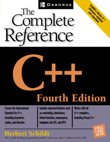
2 HOW TO START A PATRAN SESSION1234567Figure 2: On-line Help Document– Introduction to MSC.Patran– Using MSC.Patran– Interfaces– Modules– PCLThe selections to be made are indicated by numbered arrows in Figure 2, Click on the “(Closed) Book” symbol or on the label “Using MSC.Patran”. This will open up anddisplay the subheadings. Then click on “MSC.Patran Workspace”. Choose ‘Modelling Window’ from this menu (2 pages). This shows the Main form and theGraphics viewport. Part of the Main form is shown in Figure 1. Choose ‘Menu Bar’ and select ‘Menu Bar Keywords’. The items in the menu bar controls theparameters of various system tasks. This page explains the keywords in the menu bar.Below the Menu Bar is the Applications Bar. Below that is the Tool Bar. First we will consider theTool bar. Click on ‘Tool Bar’ and this should display the various palettes that make up the tool bar. Themost frequently used icons are included in the Tool bar.Figure 2 shows the contents page as it appears at this stage. Next click on the ’Applications Bar’.The essential work in using PATRAN is done by filling in the various forms in the ’ApplicationsBar’. Click on ‘Entering and Retrieving Data’ in the contents page.This will list (a) Forms, Widgets and Buttons (6 pages) (b) Selecting Entities (6 pages).These sections explain how to fill in the various forms. For the present just browse through thesepages. At this stage it is not essential reading for completing the exercise given in this handout.However these are for future reference to be read later for becoming proficient with PATRAN.5
2 HOW TO START A PATRAN SESSION2.1 Creating a New DatabaseFileRemember, this is the top menu picked.File should be the only menu selectionwhich is shown in black. This is the onlyoption that can be selected at this stage.New .Figure 3: New database The search facility is very useful. Also useful is the context-sensitive help available. When youneed more explanation on any form with a given setting leave the cursor on the form and thenpress the F1 key. After a short pause this should display the relevant information from the on-linehelp manual in a separate window. Once you have read the information close the help page. Choose File / Quit to close the help page.This way one should avoid any problem with continued use the F1 key.2.1 Creating a New Database Place the cursor on File and click the left mouse button.Unless otherwise stated in the rest of this document it will be assumed that the left mouse buttonis used for selecting menu options and items. The right mouse button is used for deselecting items; i.e.if you make a mistake in selecting an item. Choose from the menu the option New. (see Figure 3).This will bring up a form which is shown in Figure 4. In this handout form in general means aDialogue box.2.2 Opening New Database Click on the label marked ‘Change Template .’.This will open a new form (Figure 5). To use ABAQUS then click on ‘abaqus.db’ from the list of available template files to select it. Click on the OK button.This will close that form. Click on the box marked ‘New Database Name’ and type bracket and click on the OK button.This is the name chosen for the current example.The following messages should appear in the History window:1. Copying /export/./patran2003r2/abaqus.db to bracket.db.2. Template Copy complete.3. Database version 3.1 created by Version 2003 r2 successfully opened.4. Creating journal file bracket.db.jou at date time .Note that “.db” is automatically appended to the name. This denotes “database”. An empty viewport should appear with a black background. The axes will be displayed. The cross hair symbolrepresents the origin. The name of the database is displayed at the top of the viewport.Appendix A contains a brief review of the notations used in PATRAN. It also explains the purposeof the five icons (repaint, window layering, cleanup, abort and undo) displayed at the top right handcorner.When a new database is opened, the following form appears (see Figure 6).6
2 HOW TO START A PATRAN SESSION2.2 Opening New DatabaseNew DatabaseTemplate Database Name/export/./patran2003r2/template.dbChange Template .Click on thisModify Preferences .Filter/amd tmp/needle 16/usersn/userid/patran/*.dbDirectoriesDatabase List./patran/./patran/.New Database NameTypebracketbracketOKFilterCancelFigure 4: New databaseDatabase esDatabase Template Click on this forABAQUS analysis.Template NameOKFilterCancelFigure 5: Change template7Then this nameshould appear inthe box below :
2 HOW TO START A PATRAN SESSION2.3 Leaving a PATRAN SessionNew Model PreferenceModel Preference for :bracket.dbTolerancebased on ModelDefaultThis is the largest dimensionof the example problem beingconsidered.Approximate MaximumModel Dimension :10.0Change this to 100.Analysis CodeABAQUSUse theAnalysis Type :StructuralThis should display ABAQUSOKDeletecharor Deletekeyto deletecharactersResetFigure 6: Model Preference Click on the box marked ‘Model Dimension’ and change the 10 to 100.For the current example problem this is the largest dimension. The Tolerance parameter whichis used later is calculated based on this value. Therefore it is important to get this right approximately. Getting this wrong can create a few problems later. The tolerance is taken as 0.0005 ofthe largest dimension, so it will 0.05 for the current example. More on tolerance later. Click on the OK button. This will close that form.In general when entering/editing data in boxes in a form you need to click on the box first toindicate to the program that you wish to do so. In the rest of this document when reference is made toentering data in a box it will be assumed that you have to click on that box first even though this maynot be explicitly stated. Where there are exceptions to this rule it will be pointed out.The next step is to create the geometry.2.3 Leaving a PATRAN SessionYou can quit the current session at any time you wish. Make sure that the heartbeat is green. Then Click on the Quit button.All the information input and actions taken are stored in the PATRAN database so there is noneed to save before quitting.However if for some reason you want to save a copy of the database (for example to use it as atemplate) then Click on the File button Choose the Save a copy. option. Set the toggle to save a copy of thejournal file. Enter an appropriate name for the saved database.Always save a copy of the journal file : *.db.jou (here * represents the name of the database). Then wait for the Green light and choose the Quit option.8
3 STEPS INVOLVED IN AN ANALYSIS2.4 Resuming a Previous SessionAnother situation where you may want to save a copy of the database is if you want to save theresults of the current analysis before making some changes (for example using a different elementtype) and re-running the analysis and comparing the two sets of results. Then it will be a good idea towork on a copy of the original database.However you have to have enough spare disk space (quota) to be able to save a second copy of thedatabase.First time users can skip the next section (section 2.3). It explains how to open an existing databaseto continue a previous session.2.4 Resuming a Previous PATRAN Session Change to the directory where the the PATRAN database are present by typing ‘cd patran’. Choose Open. instead of New. from the File menu. Select the appropriate db file from the list of ‘available files’, by clicking on it.That file name should appear in the box marked ‘Existing Database Name’. Then click on the ‘OK’ button to choose that file.It is recommended that you use separate databases for each new analysis.If you want to look at a different PATRAN database then use File / Close to close the currentdatabase and then open the other database.3 Steps Involved in an analysisThe following is the order adopted for the various steps required for the current example.1. Decide on what units to use2. Create Geometry3. Specify Boundary Conditions and Loading on the Geometry4. Specify Material properties5. Assign material properties to geometry6. Create finite element mesh7. Create a loadcase8. Carry out the analysis9. Read results10. Post processing of the resultsBut one does not have to strictly adhere to this sequence. PATRAN provides flexibility. The usercan choose the sequence best suited for the problem in hand.For example it is better to assign the material properties to the geometry rather than the finiteelement mesh. This way if you decide to change the mesh you don’t have to re-assign the materialproperties.Similarly where necessary the specification of the boundary conditions or loading can be delayeduntil after the mesh has been generated. In general boundary conditions and loading are specified inthe geometry.The finite element mesh can be created immediately after the geometry has been created. But thereare good reasons to delay it.9
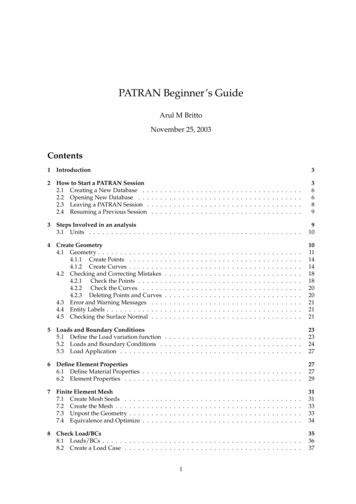
4 CREATE GEOMETRY3.1 Units10075 mm20 mm80 mmy20z80 mmxFigure 7: Example : L Bracket3.1 UnitsThere is no default set of units assumed with ABAQUS. It is the user’s responsibility to choose anappropriate set of units and enter all values using the correct units. For example the x co-ordinate of apoint is 20 mm. If you are using m for Length the value to be entered is 0.02. However if you are usingmm for Length then you need to enter 20. The same applies to all numbers being entered which haveunits associated with it.From the PATRAN program’s point of view units doesn’t mean anything (all numerical entries arejust numbers). It means that all numerical input are treated as just numbers by PATRAN. For structuralproblem the user should decide on the units for Length and Force. For time dependent problems theunit for Time also has to be chosen. Example :Length - m (metres)Force - N (Newtons)Time - Se (seconds)Then all dependent parameters must be specified in a consistent set of units. For example stiffnessshould be specified in N m2 and density in kg m3 .For the example given here the SI(mm) units are ySImNkgsP a (N/m2 )Jkg m3SI(mm)mmNtonne (103 kg )sM P a (N/mm2 )mJ (10 3J)tonne mm3SImkNtonneskP aKJtonne m3US Unit(ft)ftlbfslugslbf /f t2f tlbfslug f t3US Unit(inch)inlbflbf s2 inspsi (lbf /in2 )inlbflbf s2 in4Always choose your set of units before starting to create the geometry ie entering thepoint co-ordinates. Because this affects the stiffness parameters, loading etc. This willavoid unnecessary scaling of the results later.Note4Create GeometryThe model is a simple L bracket which is fixed along one side (vertical) in both x andy directions. Part of the other side (horizontal) is subjected to a triangular distribution10
4 CREATE GEOMETRY4.1 Geometry43112Show Labels Iconwhich varies from 100 N mm2 to 0 at the tip (Figure 7). This is an elastic analysis andcontains a single load step. The analysis consists of a single increment. The SI(mm) units have beenchosen for the present example.The bracket is 100 mm long along its side and is 20 mm thick and is 75 mm wide. This is to beanalysed as a Plane Stress problem.Points, Curves and Surfaces and Solids (for 3D) form the Geometric Entity. The Nodes and Elements of the FE mesh form the FE Entities.The bracket is to be divided into 3 surfaces. There are a number of ways to create a surface withstraight edges.1. Create the 4 points and specify these as vertices and create a surface (Figure 8a).2. Create the 4 edges of the surface using the above 4 points. Then use the 4 edges to create thesurface. This is the most tedious way to create a surface. But this is the only way to create asurface if all 4 of its edges are curved (Figure 8b).3. Create opposite edges of the surface and use these to create a surface. The 2 curves are joinedusing straight lines in creating the surface (Figure 8c).4. Create one curve (say) between points 1 and 2 and then extruded it in the Y direction to createthe surface (Figure 8d).5. Use a single step to directly create the surface (XYZ Method). Here point 1 is chosen as one endof the diagonal and then by specifying the diagonal vector the rectangle is created (Figure 8e).Some of these methods of creating surfaces will be illustrated later.4.1 Geometry Click on the Show labels icon from the Tool bar. This will display the point, curve numbers asthey are created later. Click on the 3 Geometry radio button.This will open the geometry form and display it on the right hand side of the screen. Only one ofthe forms indicated by the symbol can be open at any given time. Clicking on the label of the formwhich is currently open closes it. If you click on the label of another form the currently selected formis closed and the new form is opened.The Figure 9 shows the bracket divided into three surfaces. It is created using eight points and twocurves.The geometry form is shown in Figure 10. You will also notice a column of icons with the heading‘Pick’ displayed alongside the form. This is known as the Select Menu.If you move the cursor from icon to icon in the select menu, text explaining each icon will pop up.This is useful when picking entities. You choose an appropriate icon from this menu when needed.The default icon is the first one (shown in reverse video ie highlighted). This icon means that thecoordinates of the points are directly entered. More on this later.311
4 CREATE GEOMETRY4.1 Geometry343434121212Create 4 pointsCreate 4 pointsCreate 4 curvesCreate 4 pointsCreate 4 curves211Create 2 pointsCreate 1 curveTranslateCurve1Action : CreateObject : SurfaceMethod : re 8: Different Ways of creating a surface12CreateSurfaceExtrudeCreatedeSurfaceXYZ
4 CREATE GEOMETRY4.1 Geometrysurface 3.280206572surface 2.13423208surfacesurface 3.4Internalnumberingof curves,surfaceedges.1surface 1.1Ysurface 1.3112ZXFigure 9: L Bracket : The SurfacesFigure 10: Geometry Form1380
4 CREATE GEOMETRY4.1 Geometry4.1.1 Create PointsThe default setting of this form is for specifying directly the XYZ coordinates for the points. Notice the2 boxes labelled ‘Point ID List’ and ‘Point Coordinates List’. The first point is to be placed at the origin. Click on the Apply button to create the first point at the origin ( [0, 0, 0] ).The point number is automatically incremented for the next point. Click on the ‘Point Coordinates List’ and enter the coordinates 20 0 0 and click on the APPLYbutton. Note that the co-ordinates are enclosed by square brackets ( [ ] ).If you make any mistakes click on the ‘undo’ icon next the MSC label (top right hand corner, lasticon). This will undo the last command. In general, you can only undo the last command.At this stage you could enter the co-ordinates [ 0 80 0 ] for the 3rd point and finally [ 20 80 0 ] for the4th point co-ordinates, in order to create the first surface. However instead of that let us use a differentmethod to create the surface.4.1.2 Create Curves Change the ‘Object’ to ‘Curve’. This is done by pressing the left mouse button over ‘Point’ andchoosing ‘Curve’ by moving the mouse (while holding down the left mouse button) to that menuoption and releasing the mouse button. Now check that the ‘Method’ is set to ‘Point’. The form should be as shown in Figure 11:Notice the cursor (indicated by I) at the box marked‘ Starting Point List’. The bottom 2 boxeswhere PATRAN expects data to be entered both deal with Points. Whichever point is selectedwould be automatically placed in the first box marked ‘Starting Point List’. Click on Point 1.PATRAN now anticipates that the next selection will be the ’Ending Point’. So without clickingon the box marked ‘Ending Point List’ click on the Point 2.Now this label should appear in the 2nd box and without having to click on APPLY (becauseAutoExecute is SET) the 1st Curve will be created and displayed. The curve and its label will be inYellow.The entity selection (Selecting Point 2) for the last box acts as a trigger and executes the abovecommand.First time users might find this a little disconcerting. The ‘Auto Execute’ button can be de-activatedby clicking on it. Then you need to click on APPLY to complete the action.The next step is to create the Curve 2 by translating Curve 1. Choose the Action : ‘Transform’ instead of ‘Create’.Notice that the Curve ID List is displaying 2 in readiness for the next curve. Change the ‘Object’ to ‘Curve’ and the ‘Method’ to ‘Translate’.The form is as shown in Figure 12 :The curve 2 is created by translating curve 1 in the y direction by 80 mms. This is done by changing the ’Translation Vector’ to 0 80 0 .14
4 CREATE GEOMETRY4.1 GeometryFigure 11: Constructing linesHere DO NOT press the RETURN key after entering the ’Translation Vector’ because the form isnot complete. Otherwise a Window will appear with an error message. If it does click on OK toacknowledge it in order to proceed.Pressing the RETURN key in any of the boxes where the data are typed has the same effect asexecuting the current task i.e. clicking on the APPLY button.Therefore as a rule when typing in data refrain from pressing the RETURN key even if it is the lastbox or entry which would complete the data input to that form.This might lead to the tendency of pressing the RETURN key automatically whenever typing indata in a box even when the form is not complete.Leave the repeat count at 1, because we only require 1 curve to be created. Click on the box marked ‘Curve List’ and then click on Curve 1. The Curve 2 will be displayedwithout having to click on ‘APPLY’, if ‘Auto Execute’ is ON.The next step is to create the surface using these 2 curves. Change the ‘Action’ to ‘Create’. Change the ‘Object’ to ‘Surface’ and the ‘Method’ to ‘Curve’.The form should be as shown in Figure 13: Click on Curve 1.PATRAN now anticipates that the next selection will be the Ending Curve. So without clickingon the box marked ‘Ending Curve 2 List’ click on the Curve 2.Now this label should appear in the 2nd box. At this point without having to click on APPLY (becauseAutoExecute is SET) the 1st Surface will be created and displayed. The surface will be drawn in aGreen outline and its label will also be in Green.Of course the conventional method of clicking on the boxes before making the selection still works.Sometimes when mistakes are made use the ‘Undo’ icon and then follow the conventional method.The next task is to create the second surface in a single step using the ‘Extrude Method’.15
4 CREATE GEOMETRY4.1 GeometryFigure 12: Translate Curve16
4 CREATE GEOMETRY4.1 GeometryFigure 13: Constructing a Surface from Curves17
4 CREATE GEOMETRY4.2 Checking and Correcting Mistakes Leave the ‘Action’ at ‘Create’ and the ‘Object’ at ‘Surface’. Change the ‘Method’ to ‘Extrude’. Theform should be as shown in Figure 14: Change the ‘Translation Vector’ to 0 20 0 . Click in the box marked ‘Curve List’ and click on the ‘Curve 2’. This should create and draw thesurface in Green and display its number (Surface 2).The next task is to create the third surface in a single step. Leave the ‘Action’ at ‘Create’ and the ‘Object’ at ‘Surface’. Change the ‘Method’ to ‘XYZ’. Theform should be as shown in Figure 15: Click on the second box (marked ‘Vector Coordinates List’) and then change it to 80 20 0 .Leave the repeat count at 1, because only 1 surface is to be created. Click in the box marked ‘Origin Coordinates List’ and then click on ‘Point 4’.This should draw the surface in Green and display its number (Surface 3 ).At this point you should have the 8 Points and 3 surfaces on the screen. However if you had mademistakes you will find that you have more than 8 Points and/or 3 surfaces; do not panic. The nextsection explains how mistakes can be detected and corrected. If there are no mistakes then skip tosection 4.3.4.2 Checking and Correcting MistakesIf you think that you have made no mistakes then skip the rest of this section (goto section 4.3).Sometimes the mistakes made may be too many to be able to rectify it. Then it will be quicker todelete everything and make a fresh start. For this Change the ‘Action’ to ‘Delete’ and the ‘Object’ to ‘Any’.Make sure that the ‘Autoexecute’ option is UNSET (In case you want to change your mind).This is a drastic step. With a single action you are going to delete all Geometric entities (Points,Curves, Surfaces). This warning is mainly for future reference when dealing with a more complex/detailed situation. There is no going back. Here it is not that critical (if you make the wrongchoice) Draw a box around all the entities in the viewport.It should all change colour to light red. Click on APPLY.Otherwise the first thing to check is whether there are any duplicate points and lines.4.2.1Check the Points Click on ‘Create’ label in the Geometry form and change it to ‘Show’. Also change the other 2 options so that you have Show/Point/Location for Action/Object/Info.The ‘Total in Model’ will display the total number of points that have been created. This shouldbe 8. Click on the box marked ‘Point List’ and type ‘Point 1’, and click on ’Apply’.This will display a form with the heading ‘Show Point Location Information’. Check that theco-ordinates are correct for this point. Repeat this procedure for the 2nd point. Click on ‘Cancel’ to close that form.The next section shows how to check the curve data.18
4 CREATE GEOMETRY4.2 Checking and Correcting MistakesFigure 14: Constructing a Surface Using the Extrude Method19
4 CREATE GEOMETRY4.2 Checking and Correcting MistakesFigure 15: Creating surface - XYZ method4.2.2Check the Curves Change the options so that you have Show/Curve/Attributes for Action/Object/Info.This will display the total number of lines that h
PATRAN is a pre and post processing package for the finite element program ABAQUS. In addition it has the capability of finite element analysis. This manual has been prepared for users who want to use ABAQUS for finite element analysis. It also describes how once the ABAQUS analysis is run one could carry out some post processing.