Transcription
THE FINITE ELEMENT METHOD WITH "OVERLAPPING FINITEELEMENTS"Klaus-Jürgen BatheMassachusetts Institute of Technology, Cambridge, Massachusetts, USAABSTRACT: We review our efforts to arrive at a finite element scheme in which the elements can overlap.This property of the elements removes many of the meshing difficulties. The scheme we have been workingon for some years to render competitive is the 'method of finite spheres' (where the elements overlap) but thesame concepts can also be used for other types of element geometries. We review our latest results in staticand dynamic analyses using the method of finite spheres, and propose a general scheme for using overlappingfinite elements with traditional finite elements for CAD driven simulations.1 INTRODUCTIONThe finite element method is now established as aneffective procedure to simulate on the computer thebehavior of structures. Quite general structures canbe analyzed, from large scale to very small scalestructures, such as long and large bridges, to motorcars, to DNA structures (Bathe 2014, Bathe 2014a).However, in all finite element simulations, it is necessary to establish an appropriate and effective meshof elements, which may require a large effort for theanalyst. Since also quite some experience is neededto construct an adequate mesh, we see that mostlyonly experienced analysts can perform an effectivesimulation, even in linear analysis. The difficultiesof obtaining an adequate and hence good meshshould ideally be removed from the analysis process.These meshing considerations are quite differentfrom establishing in the first instance a propermathematical model and thus finite element modelfor simulating an event. For complex analyses, theproper modeling can be regarded to be an art because of the creativity, imagination and skill needed(Bathe 2014). In this paper we assume that themathematical model is relatively simple and that thetask of analysis is given by creating an adequate finite element mesh. In fact if a good mesh could beeasily created, the finite element method would bemuch more employed, notably by designers in theCAD environment.Since there are the difficulties of meshing, manymeshless methods have been designed, see Nayroles,Touzot & Villon 1992, Belytschko, Krongauz, Organ, Fleming & Krysl 1996, Duarte & Oden 1996,Atluri & Zhu 1998, De & Bathe 2000, De & Bathe2001a, Liu 2002 and the references therein. Muchresearch effort has been expended to develop an effective meshless method. Nevertheless, all meshless methods have been identified to be numericallyexpensive for practical use when compared with thetraditional finite element method (Dolbow & Belytschko 1999, De & Bathe 2001b, De & Bathe2001c, Mazzia, Ferronato, Pini & Gambolati 2007,Babuška, Banerjee, Osborn & Li 2008, Babuška,Banerjee, Osborn & Zhang 2009). Here we focusonly on methods that do not entail the adjustment ofnumerical factors (such adjustments are undesirablein practice) (Bathe 2014). Hence, while the overallaim of using meshless methods is very attractive,such methods have not yet found broad use in engineering practice.The objective in this paper is to review our effortsin establishing a meshless method, the 'method of finite spheres', in which the spheres are in fact 'overlapping finite elements', and propose how this concept can be used effectively in engineering practice.The key aspect is that we no longer have the restriction of traditional finite elements that they mustabut each other and can not overlap.We first review the 'method of finite spheres',presenting briefly the theory and some solution results in static and dynamic analyses. We only consider in this paper linear analysis conditions of solids. While the concepts can also be used for theanalysis of shells, fluids and nonlinear analysis, suchapplications require further research.We then present how overlapping finite elementsmay be used efficiently together with traditional finite elements to remove meshing difficulties inCAD driven analyses while at the same time not
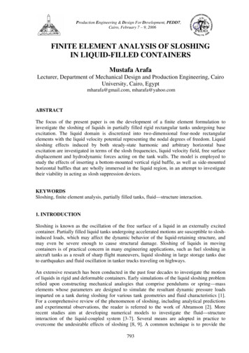
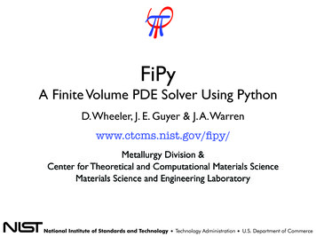
adding an undue amount of computational effort forthe system matrices.The presentation in this paper is forward-lookingwhich also means some reasonable conjectures aregiven.2 THE METHOD OF FINITE SPHERESThe solution procedure was designed in an attemptto establish a truly meshless method (a scheme thatdoes not use a spatial mesh and does not use a background mesh for numerical integration). The methodwas proposed in De & Bathe 2000 and De & Bathe2001a but was originally only tested in twodimensional static analyses. The scheme is closelyrelated to other meshless methods (Liu 2002).The objective in this section is to briefly reviewthe theory of the method of finite spheres and thengive some example solutions that demonstrate howthe method performs when compared with the use oftraditional finite element discretizations.Consider the body shown in Figure 1 discretized using spheres. For illustrative purposes we show infact disks as used in two-dimensional solutions, butin three-dimensional analysis, we would havespheres. As indicated, the spheres overlap eachother, overlap the boundary of the body, and together cover the complete body.Of course, we recall that in a traditional finiteelement mesh, the elements need to abut each otherand must not overlap, also not the boundary of theanalysis domain. Hence the only difference in thediscretization used in Figure 1 is that the overlapping is present. For this reason, we call the spheressimply 'overlapping finite elements' and we mentionin section 3 that the same concept can also be usedto construct other than spherical 'overlapping finiteelements'.Using the general principle of virtual work, as intraditional finite element analysis, we have:Find u H 1 ( Ω ) such thatTT BT SSfTSuST1(2)where N is the direction matrix, in two-dimensionalanalysis nx 0 n y N , 0 n y nx and where the overbar signifies a virtual quantity.We note that these terms furnish a symmetric contribution to the stiffness Sux1Figure 1 General problem domain V with domain boundaryS Su S f2.1 The theory of 'overlapping sphere elements' Ω ε ( v ) Cε ( u ) dΩ Ω v f d Ω v f dS λ ( u u ) dS λ v dS v H ( Ω )λ NCε ( u ) , λ NCε ( v )(1)Suwhere u is the unknown displacement field, ε is thestrain vector, C is the elasticity matrix, v is the virtual displacement field, f S is the prescribed surfacetraction vector on the boundary Sf , u S is the prescribed displacement vector on the boundary Su, f Bis the body force vector (including inertia forces)and H 1 is the first order Hilbert space. The last twoterms are Lagrange multiplier terms that impose thedisplacement boundary condition withThe stiffness and mass matrices and the load vector are evaluated from Equation (1) using numericalintegration. Much effort has been expended to obtaina reliable and efficient scheme, where we mean byreliability that the integration ensures that importantstrain terms included in the interpolation are alsocontained in the numerically evaluated matrices. Unfortunately, a high order numerical integration isneeded which is expensive.For lack of a better scheme, we use a simple standard Gauss numerical integration scheme (Ham, Lai& Bathe 2014, Lai & Bathe 201x).2.2 Evaluation in static three-dimensional analysesSome evaluations for two-dimensional solutionshave been presented in De & Bathe 2000, De &Bathe 2001a, De & Bathe 2001b, De & Bathe2001c, Hong & Bathe 2005, Macri & De 2005,however a more severe comparison is established inthree-dimensional analyses. Such analyses are morecomplex and numerically more intensive, also in therequired numerical integrations. Furthermore, staticsolutions provide a good evaluation because thestiffness matrix calculation frequently correspondsto a large part of the solution effort. For the comparison, the method was implemented in the usersupplied element routine of ADINA in order to beable to use the same sparse solver for all analyses(Lai & Bathe 201x).A cantilever beam of square hollow cross-sectionsubjected to a tip load is considered. Figure 2 showstwo finite sphere discretizations used. We note thatfor a coarser discretization, the centers of all spheres
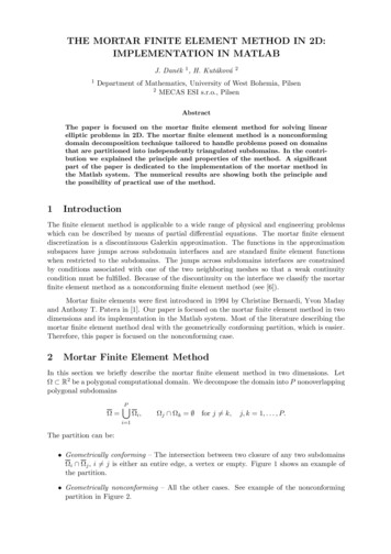
are located on the outside surface of the beam. Forspherical domains that are geometrically equal, thenumerical integration is only performed once, andthe result is then reused in the element assemblageprocess. This approach can save considerable computational time with overlapping finite elements butis, in general, only possible to some extent.Table 1 Strain energy errors and computational time multipliers for MFS and FEM discretizations (as compared to theFEM3 reference solution)Figure 2. MFS1 and MFS3 discretizations at a section for ashort cantilever beam of square hollow sectionStudying further analyses, see Lai & Bathe 201x,we see that using the overlapping spheres, the solution is between 1 to 2 orders of magnitude moreexpensive than the traditional finite element solutionusing 8-node brick elements. This conclusionbecomes more favorable towards the finite spheremethod when traditional 27-node brick elements areused (Lai & Bathe 201x). However, hereconsidering a single load case, the major numericalexpense is in establishing the stiffness matrix bynumerical integration. In practice, many load casesare solved for (indeed a hundred load cases may beconsidered) and in such cases, the stiffness matrix isonly established once, factorized once, and thenforward-reductions and back-substitutions are carried out on the load vectors. A large solution effortis then expended to solve for the different loadcases and the comparison using overlapping finiteelements with traditional finite elements will bemore favorable for the overlapping finite elementscheme.Indeed, we show this fact in the next section inwhich dynamic solutions are considered.For the traditional finite element solutions, weuse a sequence of compatible uniform meshes consisting of eight-node brick elements. The mesh refinement involves subdividing each brick elementinto eight brick elements, so that the coarser mesh isembedded in the finer mesh and we can expectmonotonic convergence.Figure 3 gives the convergence of the solutionsobtained and Table 1 gives more details on thesedata. Here the error is calculated by comparisonwith the solutions obtained using the finest traditional finite element mesh. We deem this solution tobe quite close to the unknown mathematically exactsolution. The time multiplier gives how much faster(or slower) the solution is when compared to the solution using the finest 8-node brick element mesh.However, when studying the time multipliers forcomparisons, we need to take into account the solution accuracy obtained, so here the MFS3 solutiontime might be approximately compared with theFEM2 solution time. More details on these solutionsare given in Lai & Bathe 201x.StrainTime multienergypliererror M18404.810.01FEM249201.520.05FEM332400***FEM3: Strain energy (N mm) 4096.9; Time (s) 11.64Number ofnodes2.3 Evaluations in dynamic analysesFigure 3 Convergence of strain energy for the method of finitespheres (MFS) and the finite element method (FEM)Dynamic solutions are generally obtained usingmode superposition or direct time integration. Weconsider here first a direct time integration solutionof a wave propagation problem in a two-dimensionaldomain, the data of which are taken from Ham, Lai,& Bathe 2014. A pre-stressed membrane, with aRicker wavelet applied at its center is considered.We use the implicit Bathe method for the time integration because it provides more accurate solutionsthan the trapezoidal rule, both schemes not usingany solution factor to be adjusted (Bathe & Noh2012 ).Table 2 gives the error of displacements, measured in the L2 norm for the overlapping and traditional finite element discretizations. We observe thatin this analysis, for an error of less than 4% , the approach of using spheres gives a solution time close
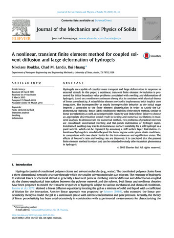
to the one used with the traditional finite elementscheme. This is clearly due to the fact that the K andM matrices are only calculated once, and the timestepping, using a major part of the solution effort,only requires vector forward-reductions and backsubstitutions.Table 2. Percent relative errors and computational times using(a) the traditional finite element method, 4-node elements, and(b) the method of finite spheres with order p harmonicsDiscretization(a) 160x160(b) 9x9, p 3Timestepsize (s)0.003125(CFL 0.5)0.00625(CFL 1)0.0031250.00625Relativeerror (%)5.593.273.5510.37Solutiontime (s)110.0659.7548.3736.99Furthermore, there is an important additional observation. Wave propagations in traditional finiteelement analyses are difficult to compute because anoptimal time step has to be selected, and this stepdepends on the speed of the wave (Bathe 2014, Noh,Ham & Bathe 2013). If the time step is larger thanthe optimal time step, the solution is unstable whenusing conditionally stable schemes (e.g. the centraldifference method) and loses accuracy when usingunconditionally stable schemes (e.g. the trapezoidalrule). Moreover, in all time integrations using traditional finite element discretizations, if a time stepsmaller than the optimal time step is used, the solution accuracy is worse. This effect can be clearlyseen in Table 2 where with a smaller CFL than theoptimal one (here 1.0) the solution error is larger.In practical analyses, there are multiple wavespeeds, (e.g. compression, shear and Rayleighwaves) of which only one can be chosen for the optimal time step selection. Therefore, the other waveswill not be accurately solved for.However, Table 2 also shows that a decrease inthe time step size using the overlapping finite elements leads to an increase in solution accuracy. Thisis an important fact and an analyst may expect thisintuitively. With this characteristic, in practicalanalyses, the largest wave speed c might be chosento establish the time step size, with the other wavesthen automatically being solved for more accurately.We can analyze the numerical dispersion erroroccurring when using a direct time integrationscheme for the traditional and the overlapping finiteelement discretizations, see Noh, Ham & Bathe2013, Kim & Bathe 201x.Here we should first note that in the method of finite spheres, an individual sphere has the same stiffness and mass properties in any direction, whereasthe traditional finite elements have different 'effec-tive' lengths depending on the direction chosenthrough the element. Therefore, the direction ofwave travel through a traditional uniform 4-nodeelement mesh will significantly affect the solutionerror, but not so for the method of finite spheres.Figure 4 shows the error in the wave speed obtained as the wave travels in the x-direction througha homogeneous arrangement of spheres with the bilinear polynomial and one harmonic in the "basis".The radius of the spheres is h, and the centers arespaced the distance h apart. A small error is obtainedat CFL 0.5 for h λh / 6 , and (as shown for CFL 1) when the spatial discretization is too coarse torepresent the wave, the Bathe method cuts out thewave response from the response prediction. Thisproperty of the time integration scheme is very useful in practical analyses because waves that cannotbe resolved are not included in the solution. Similarobservations hold for the traditional finite elementsolutions (see Noh, Ham & Bathe 2013).Figure 4. Relative wave speed errors; MFS, Bathe method;discarded wave modes dotted; λ is the wave length; x hIn the above solutions, direct implicit time integration was performed and we could conclude thatthe finite element method using overlapping spheresshows some good attributes and in some analysesmay even be competitive, compared with the traditional finite element discretizations.The other approach widely used for dynamicanalyses, but largely for structural response solutions, is mode superposition (Bathe 2014). Here themass and stiffness matrices are established and thenthe natural frequencies and mode shapes are calculated. The response is obtained by superimposing themodal responses that are excited by the initial conditions and the load vector.In the traditional finite element discretizations, byfar the largest solution effort is in calculating the required frequencies and mode shapes. Consideringthe method of finite spheres, we may conjecture thatthe method may, in some analyses, also be good insolution time compared with the use of traditional
finite elements. The reason is that the major solution effort will also be in solving the eigenvalueproblem, and not in establishing the K and M matrices. However, actual numerical comparisons shouldbe established.3 AN EFFECTIVE WAY OF MESHING USINGTRADITIONAL AND OVERLAPPING FINITEELEMENTSThe method of finite spheres, a meshless method,was designed to reduce the time of preparing a numerical model for a given physical problem; namelythe time and effort spend on meshing. In most caseshowever the method is numerically too expensive touse.Our objective in this section is to suggest that theoverlapping elements can be used effectively withvery simple Cartesian meshes of traditional finiteelements. This novel approach is in fact a furtherdevelopment of the immersed boundary cut-cell approach used in the FloEFD program of MentorGraphics for CFD analyses. The meshing is withFloEFD relatively simple and the meshing and solution procedure are tightly coupled into CAD packages.Consider the geometry of a two-dimensional partgenerated using a CAD software, like SolidWorks,as shown in Figure 5. The discretization would beperformed as follows. x yCAD partyx sFigure 5. Schematic of two-dimensional CAD part; the ( x, y) grid generated; the internal cells retained and converted to4-node traditional finite elements; the straight-line ssegmentation of the boundary; and some overlapping spheresand quadrilateral elements used along and near the boundaryThe first step is to generate a two-dimensionalgrid over the whole part, with x and y distancesbetween lines, see Figure 5. The part can be thoughtof as being 'immersed' in the grid of Cartesian cellswhich can obviously be established with negligiblehuman and computational effort.In the second step a 'characteristic straight linelength' s is used for discretizing the boundary ofthe part. This length should be small enough, so thatstraight lines of this length will represent the complete boundary of the part with sufficient accuracy,see Figure 5.This first and second step need to be automatizedto have (in general varying) x, y and s conformto the part geometry.The third step is that all Cartesian cells that donot cut the boundary are represented by traditionalfinite elements, like 4-node elements. The other cellsare removed.The fourth step is that the boundary is meshedwith overlapping finite elements using the characteristic length as spacing. It is important to place thecenters of the spheres at these boundary points (theend points of the boundary lines) because then thedisplacement boundary conditions can be easily imposed. These overlapping finite elements must extend over to the traditional finite elements (established in step 3). Usually the one layer of spheresplaced along the boundary does not extend sufficiently into the traditional finite elements and additional spherical elements need to be placed, so thatthe union of traditional finite elements and overlapping finite elements covers the complete geometricpart and displacement continuity is ensured. We illustrate this process in Figure 5 and indicate alsohow quadrilateral overlapping finite elements couldbe employed. These quadrilateral elements are formulated in the same way as the spherical elementsbut now the Shepard functions are tensor products ofthe one-dimensional functions aligned along the local element directions.In three-dimensional analysis, the same steps arefollowed but the grid is for the three Cartesian coordinate directions and a 'characteristic surface' is usedin step 2. Then traditional brick finite elementswould be employed with overlapping spheres or thethree-dimensional generalization of the overlappingquadrilateral elements.The coupling between the overlapping finite elements and the traditional finite elements is achievedas presented in Hong & Bathe 2005; see also Macri& De 2005.The effort in meshing using this approach isclearly much smaller than when using traditional finite elements throughout the analysis domain. Theaccuracy of solution for a given number of elementsmay in many analyses (like in the solution of fluidflow problems) increase because mostly undistortedelements can be used. The computational time mightbe in most cases larger than when using the traditional finite element discretizations. However, basedon all the experience reviewed above, this new approach will quite likely require much less total engineering time (time of meshing by an engineer computer solution time of finite element model),
with the actual time gained dependent on the specific analysis performed.The use of the overlapping finite elements canalso be attractive to refine a mesh, and to embedspecial functions in the approximation spaces, likeharmonic functions for wave propagation problems(as for Table 2 solutions), see e.g. Hong & Bathe2005, Ham, Lai & Bathe 2014, Kim & Bathe 201x.4 CONCLUDING REMARKSThe objective in this paper was to review our latest developments on the use of the method of finitespheres (overlapping finite elements), and then present a new meshing scheme for CAD driven finiteelement simulations.We concluded that the use of overlapping finiteelements is, mostly, computationally still very expensive in static analyses when these elements areused for the complete geometric domain. In dynamic analyses, however, the solution times usedwith overlapping finite elements compare better inexpense with traditional finite elements, since thestep-by-step solution or the solution of the eigenvalue problem require a considerable part of thecomputational effort in both approaches.Based on this experience, we finally proposed anovel scheme for meshing and finite element solutions of solids tightly coupled to the use of CADprograms. A Cartesian mesh of traditional finiteelements is used as much as possible but in conjunction with overlapping finite elements near theboundary to properly represent the boundary (andthe nearby volume) of the geometric part.This last section of the paper does not give solutions, but the proposed scheme is further presentedin Bathe 2016. The main point of the scheme usingoverlapping finite elements is that finite element solutions of solids are efficiently and directly embedded into the computer-aided design process.5 ACKNOWLEDGEMENTSThe author would like to acknowledge the cooperation of many students and colleagues, referred to inthe reference section below. This cooperation overmany years has led to results and ideas presented inthis paper.REFERENCESAtluri, S.N. & Zhu, T. 1998. A New Meshless Local PetrovGalerkin (MLPG) Approach in Computational Mechanics.Comput. Mech., 22:117-127.Bathe, K.J. 2014. Finite Element Procedures. 2nd Edition.K.J. Bathe, ADINA R & D, Watertown, MA.Bathe, K.J. 2014a. Frontiers in Finite Element Procedures &Applications, Chapter 1 in Computational Methods forEngineering Technology, (B.H.V. Topping and P. Iványi,eds.) Saxe-Coburg Publications, Stirlingshire, Scotland.Bathe, K.J. & Noh, G. 2012. Insight into an Implicit Time Integration Scheme for Structural Dynamics. Computers &Structures, 98-99:1-6.Bathe, K.J. & Zhang L. 2016. The Finite Element Method withOverlapping Elements — A New Paradigm for CADDriven Simulations, to appear.Belytschko, T., Krongauz, Y., Organ, D., Fleming, M. & Krysl,P. 1996. Meshless Methods: An Overview and Recent Developments. Comput. Methods Appl. Mech. Engrg., 139:347.Babuška, I., Banerjee, U., Osborn, J.E. & Li, Q. 2008. Quadrature for Meshless Methods. Int. J. Numer. Meth. Engng.,76:1434-1470.Babuška, I., Banerjee, U., Osborn, J.E. & Zhang, Q. 2009. Effect of Numerical Integration on Meshless Methods. Comput. Methods Appl. Mech. Engrg., 198:2886-2897.De, S. & Bathe, K.J. 2000. The Method of Finite Spheres.Comput. Mech., 25:329-345.De, S. & Bathe, K.J. 2001a. Displacement/Pressure Mixed Interpolation in the Method of Finite Spheres. Int. J. Numer.Meth. Engng., 51:275-292.De, S. & Bathe, K.J. 2001b. The Method of Finite Spheres withImproved Numerical Integration. Computers & Structures,79:2183-2196.De, S. & Bathe, K.J. 2001c. Towards an Efficient MeshlessComputational Technique: the Method of Finite Spheres.Engineering Computations, 18:170-192.Dolbow, J. & Belytschko, T. 1999. Numerical Integration ofthe Galerkin Weak Form in Meshfree Methods. Comput.Mech., 23:219-230.Duarte, C.A. & Oden, J.T. 1996. An h-p Adaptive Method Using Clouds. Comput. Methods Appl. Mech. Engrg.,139:237-262.Ham, S., Lai, B. & Bathe, K.J. 2014. The Method of FiniteSpheres for Wave Propagation Problems. Computers &Structures, 142:1-14.Hong, J.W. & Bathe, K.J. 2005. Coupling and EnrichmentSchemes for Finite Element and Finite Sphere Discretizations. Computers & Structures, 83:1386-1395.Kim, K.T. & Bathe, K.J. 201x. Transient Implicit Dynamicswith the Method of Finite Spheres, to appear.Lai, B. & Bathe, K.J. 201x. The Method of Finite Spheres inThree-dimensional Linear Static Analysis, to appear.Liu, G.R. 2002. Meshfree Methods: Moving Beyond the FiniteElement Method. CRC Press.Macri, M. & De, S. 2005. Towards an Automatic Discretization Scheme for the Method of Finite Spheres and its Coupling with the Finite Element Method. Computers & Structures, 83:1429-1447.Mazzia, A., Ferronato, M., Pini, G.& Gambolati, G. 2007. AComparison of Numerical Integration Rules for the Meshless Local Petrov-Galerkin Method. Numer. Algorithms,45:61-74.Nayroles, B., Touzot, G. & Villon, P. 1992. Generalizing theFinite Element Method: Diffuse Approximation and Diffuse Elements. Comput. Mech., 10:307-318.Noh, G., Ham, S. & Bathe, K.J. 2013. Performance of an Implicit Time Integration Scheme in the Analysis of WavePropagations. Computers & Structures, 123:93-105.
the theory of the method of finite spheres and then give some example solutions that demonstrate how the method performs when compared with the use of traditional finite element discretizations. 2.1 The theory of 'overlapping sphere elements' Consider the body shown in Figure 1 discretized us-ing spheres. For illustrative purposes we show in