Transcription
ConfidentialApplication Note for CTPMApplication Note for CTPMProject nameTouch panelDocument ref[Document ref]Version0.7Release date18 Aug 2010OwnerXiaoxu DuClassificationConfidentialDistribution List[Distribution list]ApprovalThis document contains information proprietary to FocalTech Systems, Ltd., and may not be reproduced,disclosed or used in whole or part without the express written permission of FocalTech Systems, Ltd.Copyright 2010, FocalTech Systems, LtdAll rights reservedR3-B4-A, South Area, Shenzhen Hi-Tech Industrial Park,Shenzhen, Gungdong, P.R. ChinaZIP :518057T 86 755 26588222F 86 755 26712499E .comConfidential
CTPM Application NoteRevision HistoryDateVersionList of changesAuthor Signature18 Jan, 20100.1Initial draftXiaoxu Du17 Mar,20100.2Add raw data protocolXiaoxu Du22 Mar,20100.3Add system information protocolXiaoxu Du26 Mar,20100.4Add calibration related parametersXiaoxu Du08 May,20100.5Add information to operating modeXinming Wang07 Jul, 20100.6Change Protocol and add informationYunfeng Yuan18 Aug, 20100.7Modified to release versionXiaoxu DuiiFocalTech Systems, Ltd.Confidential
CTPM Application NoteTable of Contents1I2C Interface . 21.1 CTPM interface to Host . 21.2 I2C Read/Write Interface description . 21.3 Interrupt signal from CTPM to Host . 31.4 Wakeup signal from Host to CTPM. 42CTP Register Mapping. 42.1 Operating Mode . 42.1.1DEVICE MODE . 72.1.2GEST ID . 72.1.3TD STATUS . 82.1.4TOUCHn XH (n:1-5) . 82.1.5TOUCHn XL (n:1-5). 82.1.6TOUCHn YH (n:1-5) . 92.1.7TOUCHn YL (n:1-5). 92.1.8ID G THGROUP . 92.1.9ID G THPEAK. 92.1.10 ID G THCAL. 92.1.11 ID G THWATER . 92.1.12 ID G THTEMP . 92.1.13 ID G THDIFF. 102.1.14 ID G CTRL . 102.1.15 ID G TIMEENTERMONITOR. 102.1.16 ID G PERIODACTIVE . 102.1.17 ID G PERIODMONITOR. 102.1.18 ID G AUTO CLB MODE. 102.1.19 ID G LIB VERSION H . 112.1.20 ID G LIB VERSION L. 112.1.21 ID G CIPHER. 112.1.22 ID G MODE . 112.1.23 ID G PMODE . 112.1.24 ID G FIRMWARE ID. 112.1.25 ID G STATE. 112.1.26 ID G FT5201ID . 122.1.27 ID G ERR. 122.1.28 ID G CLB. 122.2 Test Mode . 122.2.1DEVICE MODE . 142.2.2ROW ADDR. 142.2.3ROWDATAN H. 142.2.4ROWDATAN L. 152.3 System information Mode. 162.3.1DEVICE MODE . 172.3.2BIST COMM. 17iiiFocalTech Systems, Ltd.Confidential
CTPM Application Note2.3.3BIST STAT . 172.3.4BL VERH . 172.3.5BL VERL. 182.3.6FTS IC VERH . 182.3.7FTS IC VERL. 182.3.8APP IDH. 182.3.9APP IDL . 182.3.10 APP VERH . 192.3.11 APP VERL . 192.3.12 CID n(n:0-4). 193CTPM Application Introduction . 203.1 Standard Application information of FT5X06 . 203.1.1Standard application circuit of FT5206GE1 . 203.1.2Standard application circuit of FT5306DE4 . 213.1.3Standard application circuit of FT5206EE8 . 224Communication between host and CTPM . 224.1 Communication Contents. 224.2 I2C Example Code . 23ivFocalTech Systems, Ltd.Confidential
CTPM Application NoteTerminologyCTP – Capacitive touch panelCTPM – Capacitive touch panel module1FocalTech Systems, Ltd.Confidential
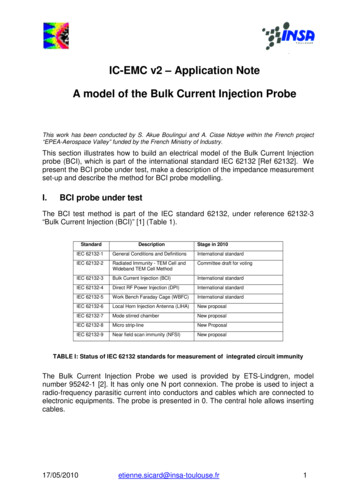
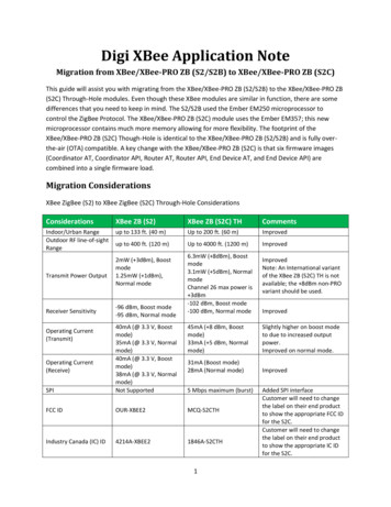
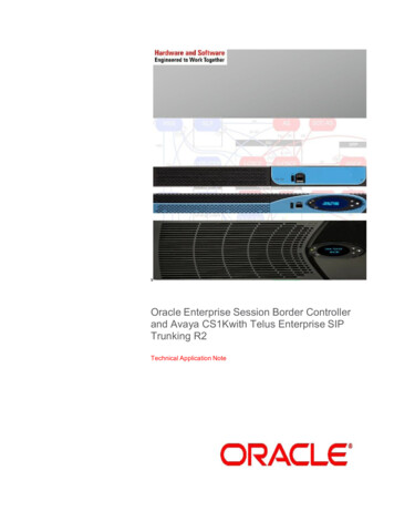
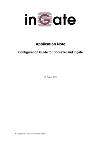
CTPM Application Note1I2C Interface1.1 CTPM interface to HostFigure 1-1 shows how CTPM communicates with the Host,there are three kind of communication betweenCTPM and Host,we will introduce each communication in this section.Transfer the data via I2CSend interrupt when there is a valid touchHost send Wakeup signal to /WAKEFigure 1-1 CTPM and Host connectionThe Power Supply voltage of CTPM is 2.8V 3.3V, interface supply voltage is 2.8V 3.3V. There are ControlInterface and Data Interface. AsFigure 1-1 demonstrates, Serial interface is the data interface, /INT and /WAKE arethe control interface. For the detail, please refer to Table 1-1.Table 1-1 Description for TP module and Host interfacePort NameVoltagePolarDescriptionSerialinterface2.8 3.3V/INT2.8 3.3VLOWThe interrupt from the CTPM to the Host/WAKE*2.8 3.3VLOWWakeup signal from host to the CTPMSerial interface is for data transfer between Host and CTPM.CTPM support both I2C and SPI interface1.2 I2C Read/Write Interface descriptionWrite N bytes to I2C slaveSlave AddrData Address[X]Data [X]Data [X N-1]A A A A A A A RR R R R R R R RD D D D D D D DD D D D D D D DSAAA A P6 5 4 3 2 1 0 W7 6 5 4 3 2 1 07 6 5 4 3 2 1 07 6 5 4 3 2 1 02FocalTech Systems, Ltd.ConfidentialSTOPACKACKACKACKWRITESTARTSet Data Address
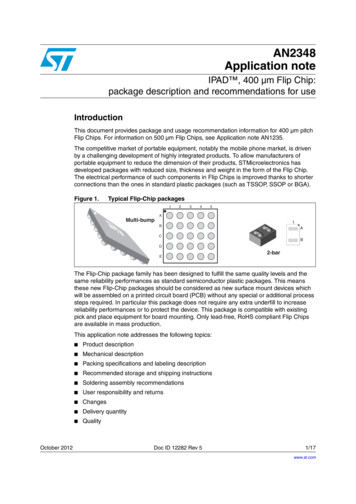
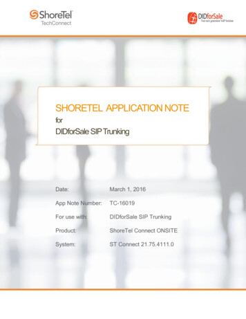
CTPM Application NoteSlave AddrData Address[X]A A A A A A A RR R R R R R R RSAA P6 5 4 3 2 1 0 W7 6 5 4 3 2 1 0STOPACKACKWRITESTARTRead X bytes from I2C SlaveSSlave AddrData [N]Data [X N-1]A A A A A A A RD D D D D D D DD D D D D D D DAA A P6 5 4 3 2 1 0 W7 6 5 4 3 2 1 07 6 5 4 3 2 1 0STOPACKACKACKReadSTART1.3 Interrupt signal from CTPM to HostAs for standard CTPM, host need to use both interrupt control signal and serial data interface to get the touchdata. There are two kind of method to use interrupt: interrupt trigger and interrupt query.Here is the timing to get touch data.Touch StartTouch End/INTSerialDataBlankData Packet0Data Packet1 Data PacketNBlankFigure 1-2 Interrupt query modeTouch StartTouch End/INTSerialDataBlankData Packet0Data Packet1 Data PacketNBlankFigure 1-3 Interrupt trigger modeHost use general I2C protocol to read the touch data or the information from CTPM . CTPM will send host ainterrupt signal when there is a valid touch. Then host can use the serial data interface to get the touch data. Ifthere is no valid touch detected, the /INT will not be pulled up, the host do not need to read the touch data.NOTE: “valid touch” may have different definition in various systems. For example, in some systems, the validtouch is defined as there is one more valid touch point. But in some other systems, the valid touch is defined asone more valid touch with valid gestures. In usual, /INT will be pulled up when there is a valid touch point, andto be low when a touch finishes.As for interrupt trigger mode, /INT signal will be low if there is no touch detected. But for per update of validtouch data, CTPM will produce a valid pulse for /INT signal, host can read the touch data periodically accordingto the frequency of this pulse. In this mode, the pulse frequency is the touch data update frequency.3FocalTech Systems, Ltd.Confidential
CTPM Application Note.1.4 Wakeup signal from Host to CTPMHost can use the Wakeup Signal to wakeup the I2C slave device.This pin should be connected to GND when flash programming while in normal running mode it should not beconnected to GND.2CTP Register MappingThis chapter describes the standard FTS Capacitive Touch Panel products communication registers in addressorder for each device mode. The most detailed descriptions of the Standard Products communication registersare in the Register Definitions section of each chapter. The device modes are listed in the table below, alongwith each mode’s register prefix.Device ModePrefixValDescriptionOperatingOp000bRead touch point and gestureTestTe100bRead raw dataSystem InformationSy001bRead system information relatedReserved2.1 Operating ModeIn this mode the CTP is fully functional as a touch screen controller. Read and write access address is justlogical address which is not enforced by hardware or firmware. Here is the operating mode register map.Operating Mode Register MapAddressNameBit7Bit6Bit
Slave Addr Data Address[X] START WRITE ACK ACK STOP. Read X bytes from I. 2. C Slave . S. A 6 A 5 A 4 A 3 A 2 A 1 A 0 R W A D 6 D 5 D 4 D 3 D 2 D 1 D 0 A D 7 D 6 D 5 D 4 D 3 D 2 D 1 D 0 A D 7 P Slave Addr Data [N] Data [X N-1] START Read ACK ACK ACK STOP. 1.3 Interrupt signal from CTPM to Host . As for standard CTPM, host need to use both .