Transcription
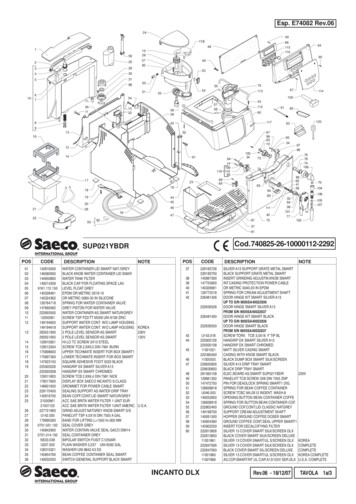
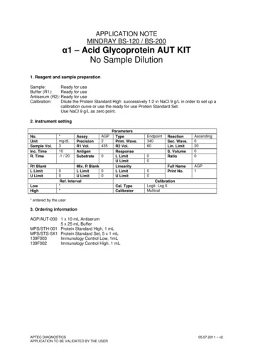
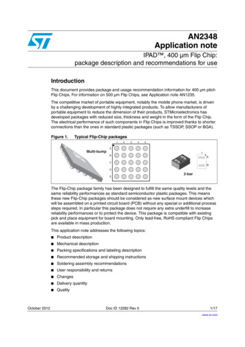
AN2348Application noteIPAD , 400 µm Flip Chip:package description and recommendations for useIntroductionThis document provides package and usage recommendation information for 400 µm pitchFlip Chips. For information on 500 µm Flip Chips, see Application note AN1235.The competitive market of portable equipment, notably the mobile phone market, is drivenby a challenging development of highly integrated products. To allow manufacturers ofportable equipment to reduce the dimension of their products, STMicroelectronics hasdeveloped packages with reduced size, thickness and weight in the form of the Flip Chip.The electrical performance of such components in Flip Chips is improved thanks to shorterconnections than the ones in standard plastic packages (such as TSSOP, SSOP or BGA).Figure 1.Typical Flip-Chip packages12345AMulti-bump1BACBDE2-barThe Flip-Chip package family has been designed to fulfill the same quality levels and thesame reliability performances as standard semiconductor plastic packages. This meansthese new Flip-Chip packages should be considered as new surface mount devices whichwill be assembled on a printed circuit board (PCB) without any special or additional processsteps required. In particular this package does not require any extra underfill to increasereliability performances or to protect the device. This package is compatible with existingpick and place equipment for board mounting. Only lead-free, RoHS compliant Flip Chipsare available in mass production.This application note addresses the following topics:October 2012 Product description Mechanical description Packing specifications and labeling description Recommended storage and shipping instructions Soldering assembly recommendations User responsibility and returns Changes Delivery quantity QualityDoc ID 12282 Rev 51/17www.st.com
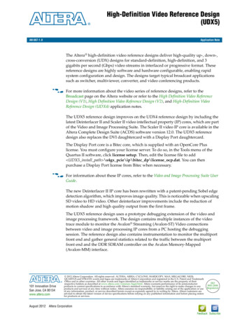
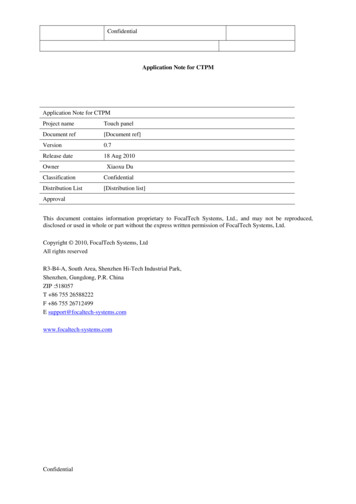
Product description1AN2348Product descriptionFlip Chips are manufactured with a wafer level process that STMicroelectronics hasdeveloped by attaching solder bumps on I/O pads of the active wafer side, thus allowingbumped dice to be produced. The I/O contact layout can be either matrix shape or set inperiphery. No redistribution layer is used. This allows parasitic inductances coming from theredistribution metal tracks to be minimized.Lead-free bump composition is 98.25% Sn, 1.2% Ag, 0.5% Cu, 0.05% Ni. This is fullycompatible with standard lead-free reflow processes. The bump dimension (255 µm bumpdiameter) allows the pick and place process to be compatible with existing equipment (inparticular with equipment used for Ball Grid Array - BGA packages) and makes it alsocompatible with the PCB design rules used for standard ICs.Optional coating on the flat side of the package is available.These components are delivered in tape and reel packing with the bumps turned down(placed on the bottom of the carrier tape cavity). The other face of the component is flat andallows picking as in the standard SMD packages.Devices are 100% electrically tested before packing. The product references are markedon the flat side of the device.2Mechanical descriptionMechanical dimensions of Flip Chips are provided through a product example in Figure 2.Bumps are lead-free. Bump composition is 98.25% Sn, 1.2% Ag, 0.5% Cu, 0.05% Ni alloywith a near eutectic melting point of 218 to 227 C. Die size and bump count are adapted tothe connection requirements.Figure 2.Mechanical dimensions of a 5 x 5 bump matrix array (sample).400 µm 40605 µm 55650 µm 601.97 mm 30 µm400 µm 40255 µm 401.97 mm 30 µmNote:2/17Optionalcoating200 µm 20200 µm 20The package height of 0.605 mm (0.650 mm for optionally coated packages) is valid for adie thickness of 0.40 mm.Doc ID 12282 Rev 5
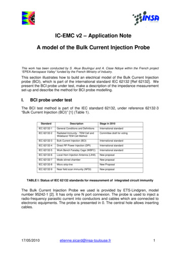
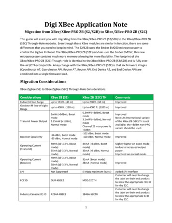
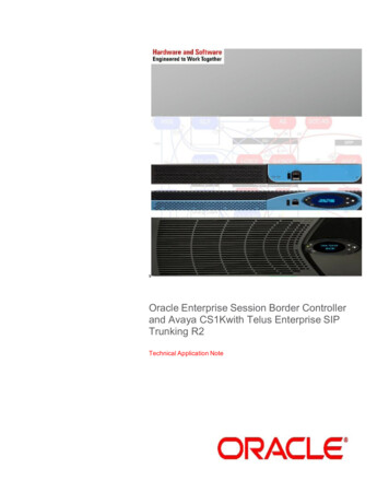
AN2348Packing specifications and labeling descriptionThe Flip Chip tolerance on bump diameter and bump height are very tight. This constantbump shape insures a good coplanarity between bumps. Optical measurements performedthrough vertical focuses show a bump plus die coplanarity below 50 µm.The product marking for the flat side is shown on Figure 3 (product example). The Flip Chiphas a pin marker - A1 (see Figure 1) on both the flat side and the bump side so that theorientation of the component can be easily determined before and after assembly. The dotsmarked on the flat side and on the bump side have been designed so that they can bedetected by standard vision systems.Marking dimensions are linked to the die size.Figure 3.Flip Chip marking example for 5x5 bump matrix array.Dot, ST logoECOPACK statusxx markingz manufacturing locationyww datecode(y yearww week)When very small die sizes leaveinsufficient space, the ST logo andECOPACK symbol are omitted fromthe marking.3x x zy wwPacking specifications and labeling descriptionFlip Chips are delivered in tape and reel to be fully compatible with standard high volumeSMD components. The features of tape and reel materials are in accordance withEIA-481-D, IEC 60286-3 and EIA 763 (783) standards. All features not specified in thissection are in accordance with EIA-481-D, IEC 60286-3 and EIA 763 (783) standards.3.1Carrier tapeFlip Chips are placed in the carrier tape with their bump side facing the bottom of the cavityso that the components can be picked-up by their flat side. No flipping of the package isnecessary for mounting on PCB. The products are positioned in the carrier tape with pin A1on the sprocket hole side. Carrier tape mechanical dimensions are shown in the example inFigure 4. Standard tape width is 8 mm for die sizes smaller than 3 mm (dimension B0).Note:12 mm carrier tape width may be used for a larger die size to be in line with EIA standards.Doc ID 12282 Rev 53/17
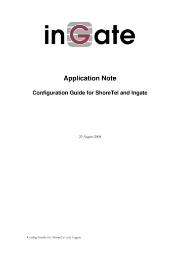
Packing specifications and labeling descriptionFigure 4.AN2348Tape dimensions for Flip Chips greater than 0.8 x 0.8 mm(605 µm or 505 µm thickness).Dot identifying b ump A1 locationA1 bump location may vary with product layoutØ ST4.01.240.69 or 0.59User direction of unreelingTypical dimensions in mm* A1 bump location varying with product layoutFigure 5.Tape dimensions for Flip Chips less than 0.8 x 0.8 mm(605 µm or 505 µm or 370 µm thickness).Dot identifying b ump A1 locationA1 bump location may vary with product layoutØ 1.552.04.03.50.798.0Cavity for2-bar Flip Chiphas center holeat the bottom1.750.20Doc ID 12282 Rev 5xxzyww4/17ST* A1 bump location varying with product layoutxxzywwUser direction of unreelingTypical dimensions in 90.69or 0.59or 0.43
AN2348Packing specifications and labeling descriptionTable 1.Tape cavity sizingDimensionDie with both sidessmaller than or equal to 1.5 mmDie with one side larger than 1.5 mmA0 and B0Die side size 70 µmCavity dimensions established to ensure thatcomponent rotation cannot exceed 10 max.The cavities in the carrier tape have been designed to avoid any damage to thecomponents. Specific hole is present to improve device stability during sealing and pick upThe embossed carrier tape is in a black conductive material (surface resistivity within10E5 and 10E11 ohm/sq). Use of this material protects the component against damagefrom electrostatic discharge and ensures the total discharge of the component prior toplacement on the PCB. Conductivity is guaranteed to be constant and not affected by shelflife or humidity. The material will not break when bent and does not have any residue to ruboff, powder, or flake.3.2Cover tapeThe carrier tape is sealed with a transparent, antistatic (surface resistivity within10E5 ohm/sq and 10E11 ohm/sq) polyester film cover tape with a heat activated adhesive.The cover tape tensile strength is higher than 10 N.The peeling force of the cover tape is between 0.08 N and 0.5 N in accordance with thetesting method EIA-481-D and IEC 60286-3. Cover tape is peeled back in the directionopposite to the carrier tape travel; the angle between the cover tape and the carrier tape isbetween 165 and 180 degrees and the test is done at a speed of 120 10% mm/minute.Doc ID 12282 Rev 55/17
Packing specifications and labeling description3.3AN2348ReelsThe sealed carrier tape with the Flip Chip is reeled on seven-inch reels (see Figure 6 for reelmechanical dimensions). These reels are compliant with EIA-481-C standard. In particular,they are made of an antistatic polystyrene material. Color of the reel may vary depending onsupplier.Dice quantity per reel is 5000 or 10000 or 15000 (with typical package thickness equal to600 µm). In compliance with the IEC 60286-3, each reel contains a maximum of 0.1% emptycavities. Two successive empty cavities are not allowed. Each reel may contain componentscoming from 2 different wafer lots.Each reel has a minimum leader of 400 mm and a minimum trailer of 160 mm (compliantwith EIA 481-C and IEC 60286-3 standards). The leader makes up a portion of carrier tapewith empty cavities and sealed by cover tape at the beginning of the reel (external side). Theleader is affixed to the last turn of the carrier tape by using adhesive tape. The trailer is atthe end of the reel and consists of empty, sealed cavities (see Figure 7).Figure 6.Seven-inch reel mechanical dimensions.Material: ANTISTATIC POLYSTYRENEABCDEW1 (Hub)180 max1.5 min13 0.5-0.220.2 min60 min8.4 1.5-0W214.4 maxAll dimensions in mmFigure 7.Leader and trailerLeader and trailerStartEndNo componentsComponentsTopcovertapeTrailerLeader160mm min .400mm min.Sealed with cover tapeUser direction of feed6/17No components.100mm minDoc ID 12282 Rev 5W3(external)8.4 2.5-0.5
AN23483.4Packing specifications and labeling descriptionFinal packingEach reel is heat sealed under inert atmosphere in a transparent, recyclable and antistaticpolyethylene bag (minimum of 4 mils material thickness).Reels are then packed in cardboard boxes.The complete description for packing is shown on Figure 8.Figure 8.Packing flow chart.dice intothe reelReel in a sealedplastic bag withininert atmosphereThe reel in its bag is packed in acardbox for storage & shipment3.5LabelingTo ensure component traceability, labels are stuck on the reels and the cardboard box. Theseven inch reels and the cardboard box are identified by labels including part number,shipped quantity and traceability references (Figure 9).The traceability is ensured for each production lot and each shipment lot through thelabeling.The trace code number printed on the labels ensures backward traceability from the lotreceived by the customer at each step of the process - in / out dates and quantity atdiffusion, assembly, test and final store. Likewise, forward traceability is able to trace a lothistory from the wafer fab to the customer’s location.Figure 9.Example of a reel labelDoc ID 12282 Rev 57/17
Packing specifications and labeling descriptionTable 2.Parameter reel labelFieldAssembled innd8/17AN2348Field typeMandatory-Country of originPb-free 2 . Level interconnectAs per JEDEC Standard JESD97MSLMandatory for concerned products as defined in MPIMoisture Sensitivity Level as per JEDEC J-STD-020Mandatory for SMDBag seal dateFor MSL 2 and above, date of vacuum sealing of dry bagFor MSL 1, “Not Moisture Sensitive” must be printed insteadPBTPeak Package Body Temperature as JEDEC J-STD-020Mandatory for the SMDCategoryPb-free category as pr JEDEC Standard JESD97Mandatory for concerned products as defined in MPIEco levelMandatory for ECOLEVEL devices only as defined in MPITypeMandatoryFirst line: Not RequiredSecond line: Raw line product nameTotal qtyMandatory - bulk quantityTrace codeMandatoryTraceability code with Wafer Fab Production Area CodeBulk IDMandatory- Bulk ID Number, Start with ABar codeMandatory-Bar code areaDoc ID 12282 Rev 5
AN23484Recommended storage, shipping instructions and descriptionsRecommended storage, shipping instructions anddescriptionsFlip-Chip reels are packed under inert N2 atmosphere in a sealed bag. For shipment andhandling, reels are packed in a cardboard box.STMicroelectronics thus recommends the following shipping and storage conditions: relative humidity between 15% and 70% temperature range from -55 C to 150 CComponents in a non opened sealed bag can be stored 6 months after shipment.Components in tape and reel must be protected from exposure to direct sunlight.Moisture sensitivity level (MSL as per JEDEC J-STD-020C) is not applicable to Flip-Chipdevices since there is no plastic encapsulation and so no risk of moisture absorption andrelated possible package cracks.Doc ID 12282 Rev 59/17
Soldering assembly recommendationsAN23485Soldering assembly recommendations5.1PCB design recommendations for multi-bump Flip ChipsFor optimum electrical performance and highly reliable solder joints, STMicroelectronicsrecommends the PCB design guidelines listed in Table 3.Table 3.PCB design recommendations.PCB pad designNon Solder Mask DefinedMicro via under bump allowedPCB pad sizeØ 260 µm max. (circular) - 220 µm recommendedSolder mask opening Ø 300 µm min. (for 260 µm diameter pad)PCB pad finishingNote:Cu - Ni (2-6 µm) - Au (0.2 µm max) or Cu OSP (Organic Substrate Protection)A too thick gold layer finishing on the PCB pad is not recommended (low joint reliability).To optimize the natural self centering effect of Flip Chips on PCB, PCB pad positioning andsize have to be properly designed (see Figure 10).Figure 10. Multi-bump Flip-Chip bump footprintCopper pad Diameter:220 µm recommended260 µm maximumSolder mask opening:300 µm minimumSolder stencil opening :220 µm recommendedMicro viasAn alternative to routing on the top surface is to route out on buried layers. To achieve this,the pads are connected to the lower layers using micro vias.10/17Doc ID 12282 Rev 5
AN23485.2Soldering assembly recommendationsPCB design recommendations for 2-bar Flip ChipsFor optimum electrical performance and highly reliable solder joints, STMicroelectronicsrecommends the PCB design recommendations listed in Table 4.Table 4.PCB design recommendations
These reels are compliant with EIA-481-C standard. In particular, they are made of an antistatic polystyrene material. Color of the reel may vary depending on supplier. Dice quantity per reel is 5000 or 10000 or 15000 (with typical package thickness equal to 600 µm). In compliance with the IEC 60286-3, each reel contains a maximum of 0.1% empty cavities. Two successive empty cavities are not .