Transcription
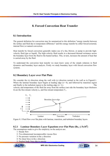
Part B: Heat Transfer Principals in Electronics Cooling8. Forced Convection Heat Transfer8.1 IntroductionThe general definition for convection may be summarized to this definition "energy transfer betweenthe surface and fluid due to temperature difference" and this energy transfer by either forced (external,internal flow) or natural convection.Heat transfer by forced convection generally makes use of a fan, blower, or pump to provide highvelocity fluid (gas or liquid). The high-velocity fluid results in a decreased thermal resistance acrossthe boundary layer from the fluid to the heated surface. This, in turn, increases the amount of heat thatis carried away by the fluidTo understand the convection heat transfer we must know some of the simple relations in fluiddynamics and boundary layer analysis. Firstly we study boundary layer with forced convection flowsystems.8.2 Boundary Layer over Flat PlateWe consider the (x) direction along the wall with (y) direction normal to the wall as in Figure8.1.Where the laminar boundary layer begins at leading edge (x 0), and followed by transition regionand finally to the turbulent region to the trailing edge (x L).Thevelocity and temperature of the fluid far away from the surface (out side the boundary layer thicknessδ) are the free-stream velocity u and free-stream temperature T .U T Boundary layer edgeδyxLaminarTransitionTurbulentFigure 8.1 Fluid flow over flat plate with laminar, transition, and turbulent boundary layers8.2.1Laminar Boundary Layer Equations over Flat Plate (Rex 5x10⁵)The assumptions made to give the simplicity on the analysis are:1- Steady flow2- Two-dimensional incompressible viscous flow3- No pressure variation in the y direction4- No shear force in the y direction5- Neglect body force due to gravityMPE 635: Electronics Cooling54
Part B: Heat Transfer Principals in Electronics CoolingAll the basic differential equations can be derived by considering an element control volume insidethe laminar region as shown in Figure 8.2.ρvyρuy yρuxρvx xyxFigure 8.2 Element control volume on laminar regionContinuity equation:{Rate of mass accumulation within control volume} {Net rate of mass flux out of control volume} 0Rate of mass accumulation within control volume ( ρ x y ) 0 (steady state assumption) tNet rate of mass flux in x- direction per unit depth ( ρ u]x x – ρ u]x ) y ( ρ u) y x xNet rate of mass flux in y- direction per unit depth ( ρ v]y y – ρ v]y ) x ( ρυ ) x y xSubstitute in continuity equation expression it produce: ( ρ u) ( ρυ ) x y x y 0 x y ( ρ u ) ( ρυ ) 0 y x (u ) (υ ) 0 x y(8.1)Momentum equation:By applying Newton's 2nd low on the same element control volume as in Figure 8.2Net rate of linearmomentum flux out ofTime rate of change ofNet rate of linearthe control volumelinear momentum withinmomentum flux out of summation of externalForx-direction:the control volumethe control volume force acting in the controlTime rate of change of linear momentum within the control volume volume( ρ u x y ) 0 tMPE 635: Electronics Cooling55
Part B: Heat Transfer Principals in Electronics CoolingNet rate of linear momentum out of the control unit (ρuu]x x – ρuu]x) y (ρvu]y y – ρvu]y) x ( ρ uu ) ( ρυ u ) x y x y x yExternal forces divided into:-Pressure force P x y x-Viscous force µ 2u x y y2Substituting in the Newton's 2nd low equation it yeilds ( ρ uu) ( ρυ u ) P 2u x y x y x y x y µ x y x y2Or,u ( ρ u) ( ρυ ) P (u ) (u ) 2u ρu u ρυ µ x x y y x y2From continuity equation we have: ( ρ u ) ( ρυ ) 0 x yThen the momentum equation for laminar boundary layer isρu (u ) (u ) 2u P ρυ µ x y y2 x(8.2)Energy equation:For the shown element control volume as in Figure 8.3.with neglected heat conduction in x-directionand applying energy balance, the energy equation may be written as follows:Energy convected in left face Energy convected in bottom face heat conduction in bottom face net viscous work done on element energy convected out right face energy convected out top face heat conduction out top faceMPE 635: Electronics Cooling56
Part B: Heat Transfer Principals in Electronics Cooling-(k x)[( T/ y) / y( T/ y) y]ρ c p[v ( v/ y) y][T ( T/ y) y] xy yρ c p[u ( u/ x) x][T ( T/ x) x] yρ u c pT y x-(k x) T/ yρ v c pT xxFigure 8.3 Element control volume for energy balanceThe viscous shear force is the product of the shear stress and the area per unit depth xµ u x yAnd the distance through which it moves per unit time in respect to the element control volume x yis u y yThe net viscous energy delivered to the element control volume2 u µ x y y By applying energy balance on the element control volume shown in Figure8.3 neglecting the secondorder differentials yields to2 T u u υ 2T T x y kρ c p u x y µ x y υ T 2 y y y x y xFrom continuity Equation 8.1 the energy equation can be written as followMPE 635: Electronics Cooling57
Part B: Heat Transfer Principals in Electronics Cooling T u T 2Tρ c p uk υ µ 2 y y x y 2Dividing by ρCpµ T T 2Tu υ α 2 x yρc p y u y 2(8.3)The viscous work term is important only at high velocities since its magnitude will be small comparedwith other terms when low velocity flow is studied. This may be shown with an order-of-magnitudeanalysis of the two terms on the right side of energy equation. For this order-of-magnitude analysiswe might consider the velocity as having order of the free stream velocity u and the y dimension ofthe order of velocity boundary layer thickness δ.u u andy δSo thatαT 2T α 22 yδ(8.4)Andµ u 2µ u ρcp δ 2ρ c p y 2(8.5)Now if the ratio between Equations 8.5 and 8.4 isµu 2u 2 Pr〈〈1ρ c pα Tc pTThen we can neglect this term compared to other terms and we can write the energy equation in thissimple form.u T T 2T υ α x y y2(8.6)The solution of these equations (continuity, momentum and energy) is simplified by the fact that, forconditions in the velocity (hydrodynamic) boundary layer fluid properties are independent oftemperature.We may begin by solving the Equations 8.1 and 8.2 (continuity, momentum) to get u and v. Then theenergy equation can be solved which depending on calculated results.The solution of Equations 8.1 and 8.2 can be solved by Blausis exact (analytic) solution for:- P 0 x- Laminar flow.In Blausis exact solution, the velocity components are defined in terms of a stream function Ψ(x,y)whereMPE 635: Electronics Cooling58
Part B: Heat Transfer Principals in Electronics Coolingu Ψ y(8.7)Andυ Ψ x(8.8)So that the continuity equation may be intrinsically satisfiedConsidering the partial differential equation describing the momentum equation (Equation 8.2), wemay use the similarity method in order to convert it into an ordinary differential equation.Defining the dependent and independent dimensionless variables ƒ and η, will help us in thisanalytical approach.f (η ) Ψ(8.9)u vx / u η y u / vx(8.10)The Blausis exact solution is termed a similarity solution, and η is the similarity variable.This terminology is used because, despite growth of the boundary layer with distance x from the leadingedge, the velocity profile u/u , remains geometrically similar as shown in Figure 8.4.yu fun.( )u δWhere δ is the boundary layer thickness and usually difficult to measureAssuming this thickness to vary as (ν x / u ) 1/2, its follows thatu fun.(η )u Hence the velocity profile is assumed to be uniquely determined by the similarity variable η whichdepends on x and y directions.u u uuδFigure 8.4 the profile u/u geometrically similarFrom Equations 8.7 and 8.8u Ψ Ψ ηvx df u y η yu dηMPE 635: Electronics Coolingu df u vxdη(8.11)59
Part B: Heat Transfer Principals in Electronics CoolingAndυ vx f u Ψ (u u x2 xυ 12vu xvu xf) df η f dη (8.12)By differentiating the velocity components, it may also be shown that uu d 2 f η x2 x dη 2(8.13) uu d2 f u yvx dη 2(8.14) 2 u u 2 d 3 f y 2 vx dη 3(8.15)Substituting these equations in the momentum equation, then we obtain2d3 fd2 ff 0dη 3dη 2(8.16)This is non linear, third-order differential equation, so that we need three boundary conditions to get asolution, these boundary conditions are:At η 0ƒ/( η) ƒ( η) 0At η ƒ/( η) u/u 1The solution of Equation 8.16 by numerical integration and the results are given in Table 8.1.At u/u 0.99 for η 5, substitute in Equation 8.10δx 5(8.17)Re xThe shear stress can be expressed as u u d 2 f τ s µ µ u vx dη 2 y y 0 η 0From the Table 8.1τ s 0.332u ρµ u xAnd the wall local shear stress coefficient Cƒ,is given byMPE 635: Electronics Cooling60
Part B: Heat Transfer Principals in Electronics CoolingτsCf 1ρ u 22 0.664(8.18)Re xTable 8.1: The function ƒ (η) for laminar boundary layer over flat plateη yu (η)dfu dη u d2 fdη le 8.1: Consider fluid flow at u 0.3 m/s past a flat plate 0.3 m long. Compute the boundarylayer thickness at the trailing edge for (a) air and (b) water at 20 oC.Solution:Part (a)From air properties table at 20 oCν 15.267x10⁻⁶ m2/s.The trailing edge Reynolds number isRe L u L(0.3)(0.3) 5895v15.267 x10 6The flow is laminar, from Equation 8.17 the predicted laminar thickness isδx 55895 0.065At x 0.3 mδ 0.0195 mMPE 635: Electronics Cooling61
Part B: Heat Transfer Principals in Electronics CoolingPart (b)From saturated water properties table at 20oC:νwater 1.0437x10⁻⁶ m2/s.The trailing edge Reynolds number isReL u L(0.3)(0.3) 86231.67v1.0437Χ10 6This again satisfies the laminar condition the laminar thickness isδx 586231.67 0.017At x 0.3 mδ 0.0051 mSolving the energy equation (Equation 8.6):Let the dimensionless temperature T T Tsand assume similarity solution of the formT T sT T (η ) , and substitute in energy equation to give this form.d 2 T Pr dT f 0dη2dη 2(8.19)Where the variable ƒ depend on the Prandtl number valuesThe appropriate boundary conditions areT (0) 0AndT ( ) 1The solution may be achieved by numerical integration method for 0.6 Pr 50 dT as the following relation.It will produce the surface temperature gradient dη η 0 dT dη 0.332 Pr1/3 η 0If Ts T Expression for the local heat convection coefficient determined as follow.q x// h x (Ts T ) k T yT Ts k Thx k (Ts T ) yTs T u hx k vx 1/ 2 T η T y y 0 η 0MPE 635: Electronics Cooling62
Part B: Heat Transfer Principals in Electronics CoolingIt follows that the local Nusselt number in this formNu x hx x 0.332 Re 1x/ 2 Pr 1 / 3k(8.20)And the average heat transfer coefficient can be obtained by integration h x 2h xxhx 1hxx 0Nu x 8.3(8.21)hx x 0.664 Re 1x/ 2 Re 1 / 3kThe Thermal Boundary LayerAnalogous to the velocity boundary layer there is a thermal boundary layer adjacent to a heated (orcooled) plate. The temperature of the fluid changes from the surface temperature at the surface to thefree-stream temperature at the edge of the thermal boundary layer as shown in Figure 8.5.T T , u TS T TSFigure 8.5.Fluid temperature variations inside the thermal boundary layerThe velocity boundary layer thickness depends on the Reynolds number ReX. But the thermal boundarylayer thickness depends both on ReX and Pr as shown in Figure8.6.Temperature boundary layerPr 1Velocity boundary layerT , u Pr 1Pr 1yδδTTSxMPE 635: Electronics Cooling63
Part B: Heat Transfer Principals in Electronics CoolingFigure 8.6 thermal boundary layer thicknesses relative to velocity boundary layer thickness at differentPrandtle numberFor laminar flow (Rex Recr):δx 5Re xAt Pr 0.7δ Pr 1 / 3δT(8.22)At Pr «1For turbulent flow (Rex Recr):δx 0.37Re 0X.2δ Pr 1 / 2δTδ δT(8.23)8.4 Cooling Air Fans for Electronic EquipmentAir is the most commonly used medium for heat transfer. It is available everywhere on the surface ofthe planet .Air is usually taken directly from the surrounding atmosphere and returned to it. Manydifferent types of fans are available for cooling electronic equipment. These can generally be dividedinto two major types: axial and centrifugal fans. These fans can be driven by various types of electricmotors, single phase, three phase, 60 cycles, 400 cycles, 800 cycle ac/dc, constant speed, variablespeed. The flow rates also vary from 1 cfm to several thousand cfm. When a fan is used for coolingelectronic equipment, the airflow direction can be quite important. The fan can be used to draw airthrough a box or to blow air through a box. A blowing fan system will raise the internal air pressurewithin the box, which will help to keep dust and dirt out of a box that is not well sealed. A blowingsystem will also produce slightly more turbulence, which will improve the heat transfer characteristicswithin the box. However, when an axial flow fan is used in a blowing system, the air may be forced topass over the hot fan motor, which will tend to heat the air as it enters the electronic box, as shown inFigure 8.7.An exhaust fan system, which draws air through an electronic box, will reduce the internal airpressure within the box. If the box is located in a dusty or dirty area, the dust and dirt will be pulledinto the box through all of the small air gaps if the box is not sealed. In an exhaust system, the coolingair passes through an axial flow fan as the air exits from the box, as shown in Figure 8.8. The coolingair entering the electronic box is therefore cooler.Figure 8.7 Axial flow fan blowing cooling air through a boxMPE 635: Electronics Cooling64
Part B: Heat Transfer Principals in Electronics CoolingFigure 8.8 Axial flow fan drawing cooling air through a box8.5 Static Pressure and Velocity PressureAirflow through an electronic box is due to a pressure difference between two points in the box, withthe air flowing from the high-pressure side to the low-pressure side. The flow of air will result in astatic pressure and a velocity pressure. Static pressure is the pressure that is exerted on the walls of thecontainer or electronic box, even when there is no flow of air; it is independent of the air velocity.Static pressure can be positive or negative, depending upon whether it is greater or less than theoutside ambient pressure.Velocity pressure is the pressure that forces the air to move through the electronic box at a certainvelocity. The velocity pressure depends upon the velocity of the air and always acts in the direction ofthe airflow. The amount of cooling air flowing through an electronic box will usually determine theamount of heat removed from the box. The higher the air flow rate through the box the higher heatwill be removed. As the airflow through the box increases, however, it requires an even greaterpressure to force the air through the box.Static and velocity pressures can be expressed in lb/in2 and g/cm2. However, these values are usuallyvery small, so that it is often more convenient to express these pressures in terms of the height of acolumn of water. The velocity head (H v) is a convenient reference that is often used to determinepressure drops through electronic boxes. The velocity head can be related to the air flow velocity asfollowV 2 gH v(8.24)Where:V Velocity of the airg gravitational accelerationH v velocity head in centimeter of waterThe Equation 8.24 can be modified using standard air with a density of 0.0012 g/cm3 at 20.5 oC and 1bar, this is shown in Equation 8.25.V 2(979.6 cm / sec 2 )(1 g / cm 3 water )( H V cm water )0.0012 g / cm 3 airV 1277 H v (cm water ) cm / sec .(8.25)The total head will be the sum of the velocity head and the static head as followHt Hv HsMPE 635: Electronics Cooling(8.26)65
Part B: Heat Transfer Principals in Electronics CoolingWe have many cases for measurement of the total heads inside the electronic box as shown in theFigures 8.9, 8.10, and 8.11. In case of a pressurized electronic box with no air flows the total pressureequal to the static pressure as shown in Figure 8.9. While in case of a fan blows air through theelectronic box, the pressure within the box will be slightly higher than the outside air pressure. Avelocity head will now be developed, as shown in Figure 8.10. But, in case of a fan draws the air throughthe box, the pressure within the box will be slightly lower than the outside air pressure, and the pressurehead characteristics will appear as shown in Figure 8.11. And the total head is still constant as shownby Equation. 8.26.Figure 8.9 a pressurized electronic box with no air flowFigure 8.10 pressure head characteristics when the fan blows air through an electronic boxFigure 8.11 pressure head characteristics when the fan draws air through an electronic boxMPE 635: Electronics Cooling66
Part B: Heat Transfer Principals in Electronics Cooling8.6Fan Performance CurveElectronic boxes that are cooled with the use of fans must be carefully evaluated to make sure the fanwill provide the proper cooling. If the fan is too small for the box, the electronic system may over heatand fail. If the fan is too big for the box, the cooling will be adequate, but the larger fan will be moreexpensive, heavier, and will draw more power.Air flowing through the electronic box will encounter resistance as it enters the different chambers andis forced to make many turns. The flow resistance is approximately proportional to the square of thevelocity, so that it is approximately proportional to the square of the flow rate in cubic feet per minute(cfm). When the static pressure of the air flow through a box is plotted against the air flow rate, the resultwill be a parabolic curve. This curve can be generated by considering the various flow resistances theairflow will encounter as it flows through the box. The method of analysis is to assume several differentflow rates through the box and then to calculate a static pressure drop though the box for each flow rate.This curve is called impedance curve for the electronic box as shown in Figure 8.12.Once the box flow impedance curve has been developed, it is necessary to examine different fanperformance curves to see how well the fans will match the box. A typical fan performance curve isshown in Figure 8.13.Figure 8.12 air flow impedance curve for the electronic boxMPE 635: Electronics Cooling67
Part B: Heat Transfer Principals in Electronics CoolingFigure 8.13 fan impedance curveIf the impedance curve for the box is superimposed on the impedance curve for the fan, they willintersect. The point of intersection represents the actual operating point for the system, as shown inFigure 8.14.Figure 8.14 intersection of fan and box impedance curves8.7Cabinet Cooling HintsIn addition to selecting a fan, there may be some choice in the location of the fan or fans, andin this regard, the illustration in Figure 8.15 may prove useful. The following comments shouldalso be kept in mind with regard to fan location:1) Locate components with highest heat dissipation near the enclosure air exits2) Size the enclosure air inlet and exit vents at least as large as the venturi opening of the fanused3) Allow enough free area for air to pass with velocity less than 7 meters/sec4) Avoid hot spots by spot cooling with a small fan5) Locate components with the most critical temperature sensitivity nearest to inlet air toprovide the coolest air flow6) Blow air into cabinet to keep dust out, i.e. pressurize the cabinet7) Use the largest filter possible, in order to reduce pressure drop and keep the system from thedust8.8Design Steps for Fan-Cooled Electronic Box SystemsThe system as shown in Figure 8.16 must be capable of continuous operation in a 55 C (131 F)ambient at sea level condition. The maximum allowable hot spot component surface temperature islimited to 100 C (212 F). The system contains seven PCBs, each dissipating 20 watts, for a total powerdissipation of 140 watts. This does not include fan power dissipation.MPE 635: Electronics Cooling68
Part B: Heat Transfer Principals in Electronics CoolingFigure 8.15 Cabinet cooling hintsFigure 8.16 plan view of fan-cooled electronic boxMPE 635: Electronics Cooling69
Part B: Heat Transfer Principals in Electronics CoolingThe flow area at the partitions designed on the drawing are as followsInlet to fan is an annuals (dimensions are in mm)48281007490o turn and transition from a round section at the fan to an oval section13Contraction and transition to rectangular section a rectangle 8 x 125 mm2Plenum entrance to a PCB duct rectangle each 1.5 x 155 mm2PCB channel duct as shown in the following drawingRectangle each 2.5 x 230 mm2 (0.1 x 9 in2)Design procedures:Two fans are available for cooling the box: Fan A is three phase 15500 rpm that has a 25 Watts motor.Fan B is single phase, with an 18 Watts motor that operates at 11000 rpm at sea level. The box must beexamined in two phases to ensure the integrity of the complete design.In phase 1, the thermaldesign of the box is examined, with the proposed fan, to make sure the component hot spot temperatureof 100 C (212 F) is not exceeded. In phase 2, the electronic chassis airflow impedance curve isdeveloped and matched with several fans, to make sure there is sufficient cooling air available for thesystem.MPE 635: Electronics Cooling70
Part B: Heat Transfer Principals in Electronics CoolingPhase 1: Electronic box thermal design:To be on the safe side, base the calculation on the use of larger, 25 W motor, Fan AThe total energy to be dissipated would then beq 140 25 165 WAir required for cooling ism qc p (t a ,o t a ,i )Past experience with air-cooled electronic systems has shown that satisfactory thermal performance canbe obtained if the cooling air exit temperature from the electronic chassis does not exceed 70 C (160 F), so that assume exit air temperature ta,o 70 CFrom the air property table at mean temperature tm (70 55)/2 62.5 Cρ 1.052 kg/m3ν 19.23 x10⁻⁶ m2/sPr 0.7Cp 1008 J/kg.Kk 0.0289 W/m.oCAir required for cooling is165 0.01091 kg/sm 1008(70 55)By calculating the heat transfer coefficient between the air and PCB's and, hence, the temperature riseof the PCB's above the ambient air. For this purpose we calculate the Reynolds' numberVD Hv4 A 4 x 9 x0.1Q DH 0.197 in 0.005 mP2(9 0.1)Re m 0.01091and V 2.55 m / sρ A 1.052 (7 x9 x 0.1) x (0.0254) 2 Re 2.55 x 0.005 66319.23 x10 -6The heat transfer coefficient for laminar flow through ducts is shown in the following relation Re Pr h DH Nu D 1.86 k L / DH 1/ 3 663 x0.7 x 0.005 1.86 8 x 0.0254 1/ 3 4.19h 24.2 W/m 2 .KThe total heat transfer isq h Seff thMPE 635: Electronics Cooling71
Part B: Heat Transfer Principals in Electronics CoolingActually, the back surface of a PCB is not available for heat transfer; the practice is to assume 30 percentonly available for this purposeS eff 7 x1.3 x8 x 9 (0.0254) 2 0.423 m 2 t h 165 / 24.2 x0.423 16.1 o CTherefore, maximum component surface temperaturet max t a,o t h 70 16.1 86.1 oCThis is acceptable surface temperature since it is less than 100 CPhase 2: Electronic chassis air flow impedance curve:The air flow conditions are examined at six different points in the chaises, where the maximum staticpressure losses are expected to occur, as shown in Figure 8.16. These static pressure losses are itemizedas follow:1Air inlet to fan290o turn and transition to an oval section3Concentration and transition to a rectangular section4Plenum entrance to PCB duct5Flow through PCB channel duct6Exhaust from PCB duct and chaisesThe following table gives the ratio between static head loss to velocity head at the different positionsPosition number123456The flow areas at each position are:Position 1: A1 π(d42o) d i2 π(0.0484Hs / H v10.90.42112) 0.028 2 1.194 x10 3 m 2Position 2: A2 0.026 x0.074 π x0.013 2 2.455 m 2Position 3: A3 0.008 x 0.125 1 x10 3 m 2Position 4: A4 0.0015 x0.155 x7slots 1.628 x10 3 m 2Position 5: A5 0.0025 x 0.23 x 7 4.025 x10 3 m 2Position 6: A5 A6 4.025 x10 3 m 2The following table gives velocity, velocity heads at each position at 10 cfm (0.283 m3/min)MPE 635: Electronics Cooling72
Part B: Heat Transfer Principals in Electronics CoolingPosition123456V (cm/s.)400376488290116116H v(cm H2O)0.0980.0870.1460.05160.00820.0082Performing the test under different cfm air flow: let the flow rate also at 20 cfm, and 30 cfmThe losses for each another flow calculated fromH (Hs / H v) H v, 10 (V )10The following table gives the static pressure loss in (cm H2O) at 10 cfm, 20 cfm, and 30 cfmPosition10 cfm20 cfm30 0.0731Total0.37611.53.3892Then drawing the chassis air flow impedance curve at different fan curves as shown belowThe minimum flow rate required for this system isV m ρ 0.01091 0.01 m 3 / s 10370.7 cm 3 / s1.052MPE 635: Electronics Cooling73
Part B: Heat Transfer Principals in Electronics CoolingFrom the impedance curve it shows:The flow rate supplied by fans A isV 30cfm 14157 cm 3 / sThe flow rate supplied by fans B isV 23cfm 10854 cm 3 / sSo that both fans A and B can supply more than the minimum required flow rate, either fan will beacceptable.MPE 635: Electronics Cooling74
Heat transfer by forced convection generally makes use of a fan, blower, or pump to provide high-velocity fluid (gas or liquid). The high-velocity fluid results in a decreased thermal resistance