Transcription
High-Definition Video Reference Design(UDX5)AN-667-1.0Application NoteThe Altera high-definition video reference designs deliver high-quality up-, down-,cross-conversion (UDX) designs for standard-definition, high-definition, and 3gigabits per second (Gbps) video streams in interlaced or progressive format. Thesereference designs are highly software and hardware configurable, enabling rapidsystem configuration and design. The designs target typical broadcast applicationssuch as switcher, multiviewer, converter, and video conferencing products.f For more information about the video series of reference designs, refer to theBroadcast page on the Altera website or refer to the High Definition Video ReferenceDesign (V1), High Definition Video Reference Design (V2), and High-Definition VideoReference Design (UDX4) application notes.The UDX5 reference design improves on the UDX4 reference design by including thelatest Deinterlacer II and Scaler II video intellectual property (IP) cores, which are partof the Video and Image Processing Suite. The Scaler II video IP core is available in theAltera Complete Design Suite (ACDS) software version 12.0. The UDX5 referencedesign also replaces the DVI daughtercard with a Display Port daughtercard.The Display Port core is a Bitec core, which is supplied with an OpenCore Pluslicense. You must configure your license server. To do so, in the Tools menu of theQuartus II software, click license setup. Then, edit the license file to add UDX5 install path \s4gx pcie\ip\bitec dp\license ocp.dat. You can thenpurchase a Display Port license from Bitec when necessary.f For information about these IP cores, refer to the Video and Image Processing Suite UserGuide.The new Deinterlacer II IP core has been rewritten with a patent-pending Sobel edgedetection algorithm, which improves image quality. This is noticeable when upscalingSD video to HD video. Other deinterlacer improvements include the reduction ofmotion shadow and high quality output from the first frame.The UDX5 reference design uses a prototype debugging extension of the video andimage processing framework. The design contains multiple instances of the videotrace module to monitor the Avalon Streaming (Avalon-ST) Video connectionsbetween video and image processing IP cores from a PC hosting the debuggingsession. The reference design also contains instrumentation to monitor the multiportfront end and gather general statistics related to the traffic between the multiportfront end and the DDR SDRAM controller on the Avalon Memory-Mapped(Avalon-MM) interface.101 Innovation DriveSan Jose, CA 95134www.altera.comAugust 2012 2012 Altera Corporation. All rights reserved. ALTERA, ARRIA, CYCLONE, HARDCOPY, MAX, MEGACORE, NIOS,QUARTUS and STRATIX words and logos are trademarks of Altera Corporation and registered in the U.S. Patent and TrademarkOffice and in other countries. All other words and logos identified as trademarks or service marks are the property of theirrespective holders as described at www.altera.com/common/legal.html. Altera warrants performance of its semiconductorproducts to current specifications in accordance with Altera's standard warranty, but reserves the right to make changes to anyproducts and services at any time without notice. Altera assumes no responsibility or liability arising out of the application or useof any information, product, or service described herein except as expressly agreed to in writing by Altera. Altera customers areadvised to obtain the latest version of device specifications before relying on any published information and before placing ordersfor products or services.ISO9001:2008RegisteredAltera CorporationFeedback Subscribe
Page 2FeaturesFeatures Files for targeting the Stratix IV GX development kit A unified memory architecture with a multiport front end to allow CPU, on-screendisplay (OSD), and video processing to use one 64-bit DDR3 SDRAM A switch block to allow run-time reconfiguration of the two video processingpaths Two active inputs, run-time selectable from: Two triple-rate serial digital interface (SDI) inputs: standard definition, highdefinition or 3 Gbps (3G), interlaced or progressive, resolution and frame rateup to 1080i60 One Display Port input: progressive, resolution and frame rate up to 1080p60Two active outputs, run-time selectable from: Two triple rate SDI outputs: SD, HD or 3G, interlaced or progressive, resolutionand frame rate up to 1080i60 One high-definition multimedia interface (HDMI) output: interlaced orprogressive, resolution and frame rate up to 1080p60 One Display Port output: progressive, resolution and frame rate up to 1080p60Two high-quality UDX video-processing paths: Low-latency motion adaptive deinterlacer with improved Sobel-based edgedetection and interpolation and cadence detection Scaler (12 12 taps) Interlacer One frame of latency (frame buffer) when inputs and outputs are locked, lessthan two frames of latency in other cases Run-time controllable frame rate conversion Genlock Alpha-blending mixer to allow multiview and OSD on one video processingdatapath—the design retrieves the OSD from a buffer in memory System initialization and run-time configuration of input and output formats andresolutions in software. Software loads from flash memory together with SRAMObject File (.sof) and OSD logos. Active format description (AFD) extraction and insertion with dynamic clipping,scaling, and padding to support 4:3 to 16:9 and 16:9 to 4:3 format conversion basedon an AFD code.High-Definition Video Reference Design (UDX5)August 2012Altera Corporation
System RequirementsPage 3 Run-time debugging: The video trace module IP monitors Avalon-ST Video protocol connections androutes protocol information to a debugging host in real time The System Monitor and Trace Monitor applications running on the hostcontrol hardware debugging agents on the board, providing systeminformation while running. For example memory bandwidth usage andperformance through the multiport front end debugging port and real-timestatus of the systemf For a full description of the Avalon-ST Video protocol and Avalon interfaces, refer tothe "Interfaces" chapter in the Video and Image Processing Suite User Guide. For moreinformation about the Avalon-MM and Avalon-ST interfaces, refer to the AvalonInterface Specifications.System RequirementsThis section describes the hardware and software requirements to run the UDX5reference design.Hardware RequirementsThe UDX5 reference design requires the following hardware components: Stratix IV GX FPGA Development Boardf For more information, refer to the Stratix IV FPGA Development BoardReference Manual. SDI HSMC boardf For more information refer to the SDI HSMC Reference Manual. Bitec HSMC Display Port cardf For more information, refer to the Bitec website. August 2012Combination of the following video sources: Up to two SDI video sources providing progressive or interlaced output up to1080p60 resolution and frame rate with BNC connectors to connect to the SDIHSMC board Up to one Display Port video source providing progressive output up to1080p60 resolution and frame rateAltera CorporationHigh-Definition Video Reference Design (UDX5)
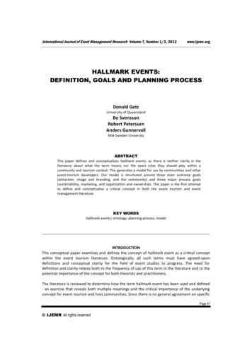
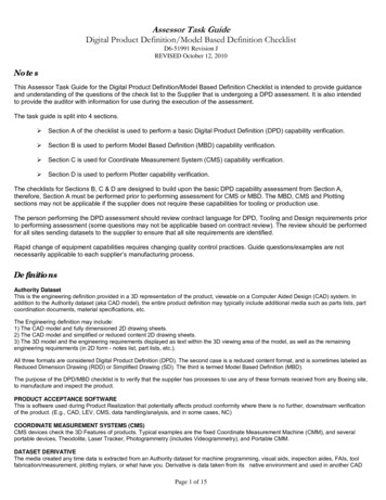
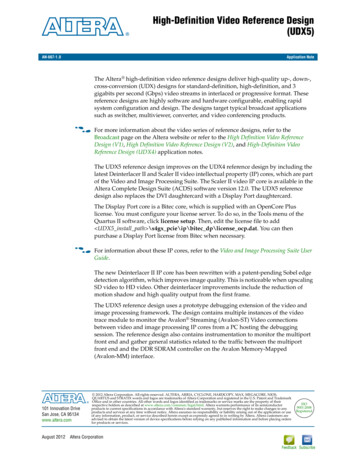
Page 4System Requirements Combination of the following video displays: Up to two monitors with Display Port or HDMI inputs supporting 1920 1080pixel resolution Up to two SDI monitors supporting 1920 1080 pixel resolutionor 1Two 3G SDI-to-Display Port converter boxes and two monitors with DisplayPort inputs supporting 1920 1080 pixel resolutionThe Altera Audio Video Development Kit, Stratix IV GX Edition provides both theAltera Stratix IV GX FPGA Development Board and the Altera SDI HSMC board.Alternatively, you can acquire the two boards separately, as the Altera Stratix IV GXFPGA Development Kit and the Terasic Transceiver SDI HSMC board. The TerasicTransceiver SDI HSMC board is available on the Terasic website. To acquire the BitecHSMC Display Port card, refer to the Bitec website.Figure 1 shows the Altera Stratix IV GX FPGA development board.Figure 1. Stratix IV GX FPGA Development BoardUser DIP Switch (SW3)Stratix IV GX FPGA (U13)CPU Reset Push-button Switch (S2)Power Monitor Rotary Switch (SW2)General User Push-button Switches (S3, S4, S5)HSMC Port A (J1)Reset ConfigurationPush-ButtonSwitch (S1)Configuration DoneLED (D5)DDR3 x64 Bottom Port(U5, U12, U18, U24)HSMC Port B(J2)Power Switch(SW1)DC Input Jack (J4)QDRII x18/x18Top Port 1 (U7)SDI Video Port(J3, J5)DDR3 x16Top Port (U14)Gigabit Ethernet Port(J6)QDRII x18/x18Top Port 0 (U22)USB Type-BConnector (J7)JTAG Connector(J8)HDMI Video Port (J11)Flash x16 Memory(U32)Character LCD (J16)SSRAM x36 Memory (U30)Transceiver TX SMA ConnectorsFan Power HeaderHigh-Definition Video Reference Design (UDX5)Max II CPLD EPM2210 System Controller (U31)PCI Express Edge Connector(J17)Clock Input SMA Connector (J14, J15)Clock Output SMA Connector (J9)August 2012Altera Corporation
Resource UtilizationPage 5Software RequirementsThe UDX5 reference design requires the following software: The Altera Complete Design Suite v12.0, which includes the Quartus II software,Qsys, Nios II EDS, and MegaCore IP Library (including the Video and ImageProcessing Suite) Windows XP or Linux OS1Only the Windows XP OS supports the debugging applications to monitorthe system on the host. These applications also require a Java VirtualMachine version 1.6. You must use a 32-bit Java Virtual Machine on a 64-bitoperating system.Resource UtilizationTable 1 shows the resource utilization for the UDX5 reference design.Table 1. Resource UtilizationCombinationalALUTsALMsDedicated 110,97059115311UDX5 without debugging88,25077,900101,97051715311DesignAugust 2012Altera CorporationHigh-Definition Video Reference Design (UDX5)
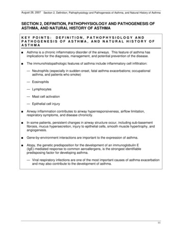
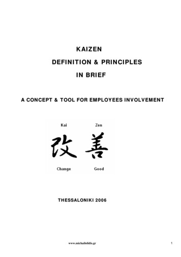
Page 6High-Definition Video Reference Design (UDX5)Functional DescriptionFigure 2 shows a detailed block diagram of the UDX5 reference design.Figure 2. UDX5 Reference Design Block DiagramRGBQuartus II HDLDisplayPort24DisplayPortClockedVideo InputFrame Rate ConversionDP ColorSpaceConverterSDIDVI20(1)24DP dge-AdaptiveScalerFrameBufferInput ChannelChromaResamplerNios II20YCrCbY YCb CrAFDExtractorDVIClockedVideo InputDVI ColorSpaceConverterRGBColor SpaceConverterConstantAlpha Source1DDR3 HP2MemoryControllerMulti-Port Front EndSDIClockedVideo InputInput rGather DMADVIChromaResampler calerY YCb CrChromaResamplerFrameBufferFrame Rate ConversionYCrCbColor SpaceConverterConstantAlpha Source2Input ChannelOSD ChannelQsysLegendVIP Core, Note (2)TestPatternGeneratorTPG ColorSpaceConverter1Not in Version acerGammaConnectorOutput izerInterlacerGammaConnector3OSD ColorSpaceConverterOutput Selector BlockOutputSwitchRGB30DVIClockedVideo Output2430HDMIClockedVideo Output2430OutputChromaResamplerOutputChroma30 Y ResamplerCrCb20AFDInserterSDIClockedVideo Output20AFDInserterSDIClockedVideo OutputY YCb Cr20(1)20(1)DisplayPortSDISDIDVINote to Figure 2:(1) For SD, use 10 LSBs.(2) Run-time configurable via register map (Avalon-MM slave interface). Configuration changes (for example, viewing mode changes, scaler coefficient reload) performed by the software executing on theNios II processor.Functional DescriptionAugust 2012 Altera Corporation2TPG ColorSpaceConverterColor PlaneSequencerOutput Channel3TestPatternGeneratorFrameReaderAV-ST Video Trace
Functional DescriptionPage 7The UDX5 reference design comprises two video processing paths. This sectiondescribes a functional description of the blocks in both paths.UDX5 Reference Design BlocksMost of the blocks in the UDX5 reference design are instances of Video and ImageProcessing Suite IP cores. Altera parameterizes all of the IP cores with a maximumresolution of 1920 1080 pixels. Table 2 describes the blocks.Table 2. Reference Design Blocks (Part 1 of 3)Reference DesignBlockMegaCore FunctionDescriptionAFD clipper ( 2)ClipperClips input images based on the detected AFD code and removes theletterbox or pillarbox.AFD extractor ( 2)AFD ExtractorExtracts AFD code (0 to 15) from Avalon-ST Video ancillary packets.Supports access to the AFD code through an Avalon-MM slave controlinterface.AFD inserter ( 2)AFD InserterInserts the AFD code (0 to 15) the AFD Inserter receives on itsAvalon-MM slave interface to an Avalon-ST Video ancillary packet (type0xD).AFD mixerAlpha Blending MixerSecond stage of the AFD correction. Adds letterbox bars or pillarbox barsto the second video input channel.AFD mixer bypassswitchSwitchIn multi-view mode, sends the second video input channel to the OSDmixer; in independent mode, sends the second video input channel andthe test pattern to the AFD mixer.Video trace moduleVideo trace moduleFourteen video trace modules allow debugging of the design. Themodules use a global timestamp. Arbitration and hardware use the JTAGcable to link between the video trace modules and the debugging host.Chroma resampler( 2)Chroma ResamplerProvides YCbCr 4:2:2 to YCbCr 4:4:4 upsampling.Color plane sequencerColor Plane SequencerSplits the red, green, blue, alpha (RGBA) input to two output streams, oneRGB and one A, on separate Avalon-ST ports.Color space converterColor Space ConverterRun-time configurable to convert the 10-bit RGB or YCbCr input format to10-bit RGB or YCbCr, depending on the color spaces of the input andoutput videos.Constant alpha source( 2)Chroma Key (beta)Outputs a constant alpha value synchronized to the video stream. Runtime configurable to alter the alpha value on a frame-by-frame basis.Control synchronizer( 2)Control SynchronizerEnsures that switching of the relevant mixer switch is synchronized to thestart of an image packet in the video stream, so t
trace module to monitor the Avalon . Reference Manual. SDI HSMC board f . (U5, U12, U18, U24) General User Push-button Switches (S3, S4, S5) Power Monitor Rotary Switch (SW2) Power Switch (SW1) User DIP Switch (SW3) DC Input Jack (J4) QDRII x18/x18 Top Port 1 (U7) DDR3 x16 Top Port (U14) QDRII x18/x18 Top Port 0 (U22) JTAG Connector (J8) PCI Express Edge Connector (J17)