Transcription
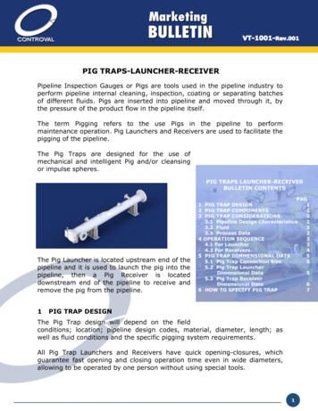
PIG TRAPS-LAUNCHER-RECEIVERPipeline Inspection Gauges or Pigs are tools used in the pipeline industry toperform pipeline internal cleaning, inspection, coating or separating batchesof different fluids. Pigs are inserted into pipeline and moved through it, bythe pressure of the product flow in the pipeline itself.The term Pigging refers to the use Pigs in the pipeline to performmaintenance operation. Pig Launchers and Receivers are used to facilitate thepigging of the pipeline.The Pig Traps are designed for the use ofmechanical and intelligent Pig and/or cleansingor impulse spheres.PIG TRAPS LAUNCHER-RECEIVERBULLETIN CONTENTSThe Pig Launcher is located upstream end of thepipeline and it is used to launch the pig into thepipeline, then a Pig Receiver is locateddownstream end of the pipeline to receive andremove the pig from the pipeline.1PAG1 PIG TRAP DESIGN12 PIG TRAP COMPONENTS23 PIG TRAP CONSIDERATIONS23.1 Pipeline Design Characteristics23.2 Fluid23.3 Process Data24 OPERATION SEQUENCE34.1 For Launcher34.2 For Receivers45 PIG TRAP DIMMENSIONAL DATA55.1 Pig Trap Connection Size55.2 Pig Trap LauncherDimensional Data55.3 Pig Trap ReceiverDimensional Data66 HOW TO SPECIFY PIG TRAP7PIG TRAP DESIGNThe Pig Trap design will depend on the fieldconditions; location; pipeline design codes, material, diameter, length; aswell as fluid conditions and the specific pigging system requirements.All Pig Trap Launchers and Receivers have quick opening-closures, whichguarantee fast opening and closing operation time even in wide diameters,allowing to be operated by one person without using special tools.1
Controval has the capability to custom design pig launcher/receiver to workwith most fluid conditions and field requirements.2PIG TRAP COMPONENTSThe pig traps main components are: 3Barrel Closure (1)Local drain (2)Gas vent (3)Pressure relief (4)Kicker line (5)Pressure gauge connection (6)Pig launcher-Receiver Balancing Line (7)Pig-sig (8)Pig launcher-Receiver discharge (9)PIG TRAP CONSIDERATIONSThe design of a Pig Launcher / Receiver unit must consider the specificapplication to handle. To perform a suitable selection and arrangement of thedevices involved it is required to identify the following parameters:3.1 Pipeline Design Characteristics:Design codes, rating, diameter, material of construction, length3.2 Fluid:Fluid name, flow rate, properties3.3 Process Data:Pressure and Temperature ranges of the fluid.2
4OPERATION SEQUENCE4.1 For LaunchersInitial condition:The trap is pressurized and completely loaded of gas. Mainline valve A,bypass valve B and kicker valve C are open. Vent valve D is closed.SCHEMATIC VIEW - LAUNCHING EXPLANATIONI.II.III.IV.V.VI.VII.Close mainline trap valve A and kicker valve C.Open vent valve D to vent the launch trap to atmospheric pressure.When the trap is completely vented (zero manometric) with vent valve D stillopened, open the closure door and insert the “PIG tool”, adjusting itself intoreduction (R) previous to A valve with the first cup of the tool.Close and secure the closure door. Purge the air from the trap through vent valveD by slowly opening kicker valve C. When the purge is done, close vent valve Dto allow pressure equalization between trap and pipeline, then close kicker valveC.Open mainline valve A, then kicker valve C. The “PIG tool” is ready to belaunched.Close partially bypass valve B. This will increase the gas flowrate through kickervalve C and behind the “PIG tool”. Continue closing B valve until the tool goesout of the trap inserting itself into the pipe current indicated by the "PIG-SIG“passage indicator.When the “PIG tool” is launched from the trap and comes into the mainline, openbypass valve B completely.3
4.2 For ReceiversInitial condition:The trap is empty at atmospheric pressure. Bypass valve B, vent valve D anddrain valve E are open; Mainline valve A and return valve C are closed. Theclosure door is closed and secured.SCHEMATIC VIEW - RECEIVING EXPLANATIONI.II.III.IV.V.VI.VII.VIII.IX.Drain the trap, close drain valve E and open slowly return valve C.Once it is drained, start equalizing the pressure in the trap closing vent valve Dwith the kicker valve C opened.With return valve C still opened, open mainline valve A. The trap is now ready toreceive the “PIG tool”.When the “PIG tool” arrives, this will stop between mainline valve A and theentrance tee piece (R) of the trap.Close partially bypass valve B. This will force the “PIG tool” to introduce itself intothe trap increasing the gas flow through return valve C.After the “PIG tool” is in the trap, shown by the "PIG-SIG“ passage indicator,open bypass valve B and close A and C valves.Open vent valve D and drain valve E to vent the trap to atmospheric pressure.After the trap is vented and drained with D and E valves opened, open theclosure door and remove the “PIG tool”.Close and secure the closure door.4
5PIG TRAP DIMENSIONAL DATA5.1 Pig Trap Connections SizeNOZZLESIT E MS E R V IC ED E S C R IP T IO N1234567891011KICKER LINELOCA L DRA INP RESSURE GA UGE CONNECTIONGA S VENTP RESSURE RELIEFP IG LA UNCHER B ODYB A RREL CLOSUREP IG-SIG (OP TIONA L)P IG LA UNCHER B ODY SWITCHLIQUID DISCHA RGELOCA L DRA INWELDOLET, COUP LING & FLA NGEWELDOLET, COUP LING & FLA NGETHREA DOLETWELDOLET, COUP LING & FLA NGETHREA DOLETFLA NGEB A RREL QUICK A CTION CLOSURECOUP LING WELD TO P IP ECOUP LING WELD TO P IP EWELDOLET, 90 ELB OW, COUP LING & FLA NGEWELDOLET, COUP LING & FLA ��10 �P IP E D IA M E T E R ( in)12 ”16 2”10"3”5.2 Pig Trap Launcher Dimensional DataSECTION A-ADIMENSIONS (mm)P ipe D ia .( in)B a rre l D ia .( in)C o nt ro v a lP re f 0”12”16”20”24”30”34”42”CP L-6CP L-8CP L-10CP L-12CP L-16CP L-20CP L-26CP L-30CP L-36WT . ( 89LA UN C H E 2903144404505305806607108105
5.3 Pig Trap Receiver Dimensional DataSECTION B-BDIMENSIONS (mm)P ipe D ia .( in)B a rre l D ia .( in)C o nt ro v a lP re f 0”12”16”20”24”30”34”42”CP R-6CP R-8CP R-10CP R-12CP R-16CP R-20CP R-26CP R-30CP R-36WT . ( 085609050883088401020011100B 230230230300300320380R E C E IV E RGHI12006009002800 100021002800 1050 22202650 100021002800 1050 22302540 102021302480 100019003080117024003280 1280 6
6HOW TO SPECIFY PIG TRAPCONTROVAL PRODUCTCPPIG TRAPPIG TRAP TYPELLauncherRReceiverSIZE06Pipe Diameter 6 in08Pipe Diameter 8 in10Pipe Diameter 10 in12Pipe Diameter 12 in16Pipe Diameter 16 in20Pipe Diameter 20 in26Pipe Diameter 26 in30Pipe Diameter 30 in36Pipe Diameter 36 inANSI RATING15ANSI 15030ANSI 30060ANSI 600MATERIALSSStainless SteelSASpecial AlloySUPPORT TYPESP1SkidSP2SaddlesOPTIONAL FEATURESCDIICP -R1260SS1Cover DavitInstrumentation IncludedWSASME & NB StampOCOther Construction CodesLLLifting LugsCTProver RequiredII-WS-SP2-LL7
pigging of the pipeline. The Pig Traps are designed for the use of mechanical and intelligent Pig and/or cleansing or impulse spheres. The Pig Launcher is located upstream end of the pipeline and it is used to launch the pig into the pipeline, then a Pig Receiver is located downstrea
