Transcription
GE Oil & Gasapplication noteBently Nevada*Asset Condition MonitoringConnecting SCOUT* to ContinuousMonitoring SystemsThe most effective installations of continuous monitoringinstruments—such as the 3500 system—include integration withthe System 1* Condition Monitoring (CM) Platform. However,monitoring systems are sometimes used in a “stand-alone”Continuously Monitored Assetsinstallation, without the benefits of a CM platform. With such an Critical assets customarily have continuous monitoring systemsapplication, the monitor system provides continuous automaticthat provide the operations team with real-time informationshutdown protection for the monitored assets, but it doesabout the asset’s condition. These systems can includenot store data for use in condition monitoring and diagnosticautomatic shutdown, and are the focus of this document.evaluations.Periodically Monitored AssetsOne way to increase the CM capabilities of a stand-alone monitor The majority of plant assets fall into this category. Monitoringsystem is to collect periodic samples from the buffered outputscan range from simple indicators (gauges, LEDs, visual,as part of an existing “walk-around” program. Historical dataetc.) next to the machine that are periodically reviewed byfrom the monitor system is then available for long-term trendingoperations to a full CM program with a portable data collectorand diagnostics.(PDC).This document provides guidance on how to incorporate theUnmonitored Assetscollection of vibration data from an online monitoring system Monitoring and/or CM are not practical due to low criticalitywith a condition monitoring program enabled by SCOUT portabledevices and Ascent software.Plant Assets and Monitoring PhilosophiesThe typical industrial plant consists of a diverse range of assetsthat combine to provide a service such as the generationof electricity or production of petroleum based products.(cost, spare capacity, etc.)Condition Monitoring OverviewCM involves trending and alarming on important parametersthat provide clues about the operating condition of an asset overtime. Examples of such parameters include vibration, bearingtemperature, process flow, and thermodynamic efficiency.Maintenance and operational philosophies are generallyestablished based on the criticality of the individual assets andThe goal of this strategy is to enable intelligent planning for assettheir role in the given system. At a high level, assets fall into threemaintenance based on conditional information, as opposedcategories: “continuously monitored,” “periodically monitored,”to reactively solving problems when they arise or applyingand “unmonitored.”premature maintenance to assets that could have continued tooperate without consequence.Well-organized CM programs can reducemaintenance costs and improve plant reliabilityООО «Сервис Генерации» 7 (499) 992-09-90121357, Москва, ул. Инициативная, дом 7, кор. 3, помещение 15dme.bz
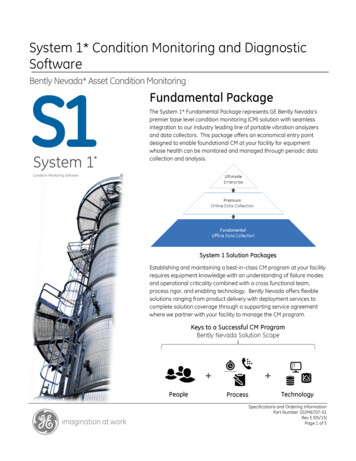
application noteCM Platform RecommendationsSystem 1 for Continuously Monitored Assets Bently Nevada’s System 1 software platform represents the CMsolution for continuously monitored machinery. Vibration dataprovided by Bently monitoring systems can be combined withprocess information to provide real-time asset health analysiswith long-term trending, alarming, and analytical capabilities.What to do when an online monitoring system like3500 has not been connected to System 1 GE’s Bently Nevada Ascent* software combined with a SCOUTseries data analyzer can be configured to collect periodic datafrom these systems. This will enable basic condition monitoringfor the critical asset. Monitor the axial position of the shaft Bias Voltage for applicable acceleration and velocity probes Monitor Sensor HealthCoast-Down/Run-Up Bode plot analysis, identify and analyze resonant frequencies(rotor and structural)Balancing Single and Multi-PlaneStep 3: Example ConfigurationThe subsequent example describes how to configure dual-channelsynchronous measurements with gap voltage for radial vibrationapplications. Configuration is performed in Ascent* software andthen downloaded to SCOUT instrumentation. Modifications can bemade if single channel collection or asynchronous waveforms areStep 1: Understand the Systempreferred.For optimal SCOUT configuration, consider the questions belowThe same methodology can be used to configure measurementsprior to configuration:for acceleration or velocity data. Gap voltage will be replaced with Is the monitoring system configured to automatically trip themachine, and if so what conditions will cause a trip?bias voltage for applicable sensors.Ascent* Software Configuration What application is the monitor configured for? (radial vibration,acceleration, thrust, etc.) How is the monitor configured? (Variables, filters, set points, etc.)Step 2: Measurement ChoicesUseful measurements supported by SCOUT instrumentation:Dynamic (Waveform) Data Asynchronous [no tach] and Synchronous [tach] SamplingFigure 1: Ascent “Data Folder” Configuration Spectrum (spec)Data Folder Configuration Steps (Figure 1): Overall [rms]1. Configure a “New Machine” for the asset. Set “Default Speed” Spectral Bands [0.5X, 1X, Blade Pass etc ]and set “Main Shaft Rotation” direction so that Orbit Plots are Waveform (Wfm) Waveform True Pk-Pk Crest Factordrawn properly.2. Create new “Point” for the bearing location.3. Create “Measurement Location” for the sensor. Ascent has Orbit Plots [Dual Channel Required] Dynamic motion of the shaft centerline within bearingmeasurements. The angular orientation for these locationsclearancedefaults to 0 and must be adjusted for each Axis so that OrbitAverage Value RecordingPlots are drawn properly. See Figure 2. Gap Voltage for Proximity Probes Monitor position of shaft within bearing clearance Monitor Sensor Health Thrust PositionООО «Сервис Генерации»default Axis locations X and Y intended for proximity probe 7 (499) 992-09-904. Configure “Schedule Entry” [waveform/spectrum]. See Figure 3.121357, Москва, ул. Инициативная, дом 7, кор. 3, помещение 15dme.bz
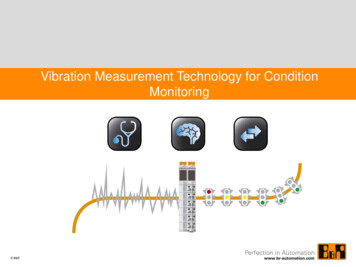
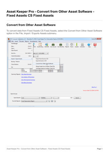
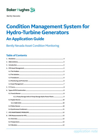
application note5. Configure Average Value “Schedule Entry” for the gap voltagemeasurement. See Figure 5.Wfm/Spec Configuration Steps (Figure 3):Waveforms and spectra also referred to as dynamic data provide6. Copy/Paste bearing configuration required number of times.Create Route for the newly created machine upon completion.the backbone of the analysis and CM capabilities within Ascent.Trended variables such as Waveform True Pk-Pk, Overall (O/All)Energy, and Spectral Bands are derived from dynamic data.1. Select data type: spectrum, waveform or both, and desired units.1This example demonstrates a radial vibration configuration.2. If synchronous data is desired, check “Tach Triggered” box.3. Select appropriate “Tach Type” for application. If tach type isa Keyphasor*, default selection should be “Keyphasor 13V.”SCOUT will prompt user to select a different option during data3collection if necessary. Multiple Keyphasor “trigger” options areonly available for SCOUT devices with serial numbers greaterthan 45,000.4. Select sample resolution.25. Select number of shaft revolutions desired and check “OrderTracked” box so that true synchronous sampling is enabled.Figure 2: Axis Angular OrientationExample shown will collect 128 samples per shaft revolutionAxis Angular Orientation Configuration (Figure 2):1. Select “Add/Edit” from Measurement Location edit menu.2. Select “Axis Name” to change the angular orientation, or add anew one if it does not exist.[2048 samples/16 revolutions].6. Averaging is not typical for displacement measurements, so set“Number of Averages” to 1. This results in NO AVERAGING.7. Configure “Channel/Sensor,” see Figure 4.3. Select “Edit” and type in angular location for selected axis.1123234754566Figure 4: Displacement Transducer ConfigurationAC-Coupled Sensor Configuration (Figure 4):Figure 3: “Schedule Entry” ConfigurationООО «Сервис Генерации» 7 (499) 992-09-901. Select appropriate Sensor.121357, Москва, ул. Инициативная, дом 7, кор. 3, помещение 15dme.bz
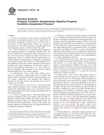
application note2. To add or edit existing sensor properties, select “Sensors.”Sensor Setup Dialog Box:calculated. 1000 ms worked well in the example shown.3. Select appropriate “Sensor Units.”2. Select Sensor. Sensor output must NOT be AC-Coupled. Select4. Select “Input Range and Coupling” for sensor type.Sensors button to add or edit a sensor configuration.Recommend AC /- 8V for most applications.1. Configure Duration (msec) over which average value is to beSensor Setup Dialog Box:- Removes DC component [gap or bias voltage] so that timewaveform can be centered around zero engineering units3. Select Sensor Units. If voltage is desired, select Electro-MotiveForce (mV/V).4. Select appropriate DC-Coupled Input Range and Coupling foron Y-axis5. Enter sensor “Sensitivity/Calibration.”the given sensor. Typically, Bently Nevada probes are powered6. Ensure that “Enable Drive Current” checkbox is NOT selected.by negative voltage, so select DC -20 0V.Click OK, sensor is configured.5. Select Sensitivity/Calibration for sensor, 1000 mV/V ifmeasurement is in voltage.6. Select 0 for DC Offset.1Thrust Position Configuration Steps (Figure 5):Machines that experience axial loading during operation (SteamTurbine, Pump, Compressor, etc.) have thrust bearings designed to2constrain the axial motion of the shaft. Proximity probes measurethe axial position of the shaft relative to their installed position,which can be on the thrust bearing viewing the thrust collar, or3if this is not feasible, a position very close to the thrust bearing4viewing an exposed section of shaft.5Collecting thrust position from a monitor is very similar to thatof gap voltage; with a few extra steps required to ensure that6the SCOUT measurement matches that of the monitor. Start byconfiguring a new Average Value Schedule Entry for the thrustposition measurement, and then refer to Figure 5 and follow thesteps below:1. Set Duration (msec) to 1000 ms.Figure 5: Gap Voltage and Thrust Position Measurement Configurationposition application within the database because the DCGap Voltage Configuration Steps (Figure 5):Trending the “Gap Voltage” for proximity probes monitoring radialvibration is highly recommended. This important parameterrepresents the DC component of the proximity probe signal andprovides information about the position of the shaft centerlinewithin a journal bearing and the health of the sensor itself. Valuable parameter for CM, as certain conditions can cause theposition of a shaft to change within its bearing housing withoutcausing a noticeable change to the radial vibration, which is whytrending and alarming on gap voltage is very useful.average value is calculated from a DC-Coupled waveform. 7 (499) 992-09-90Offset (0mV ) is unique for each application and dictated bythe monitor configuration.3. Select Sensor Units.4. Select Input Range and Coupling to DC -20 0V.5. Select Sensitivity/Calibration for sensor. Must be ( ) forapplications where the “Normal Thrust Direction” is “TowardProbe” and (-) when “Away From Probe.” This information iscontained in the monitor configuration.6. Set the DC Offset (0mV ) to the configured “Zero Position(Direct)” configured in the monitor. This value must be ( ) for To produce the DC component of the transducer signal, anООО «Сервис Генерации»2. A new sensor will likely have to be created for each thrustapplications where the “Normal Thrust Direction” is “TowardProbe” and (-) when “Away From Probe.” The DC Offset (0mV )121357, Москва, ул. Инициативная, дом 7, кор. 3, помещение 15dme.bz
application noteentry must be in units of displacement, refer to the exampleprovided below.Thrust Example:Configuring the SCOUT PDC for Dual ChannelRecordingsNow that the software has been configured and the route has beenA 3500 monitor has been configured to measure thrust positiondownloaded to the PDC, the instrument must be configured towith a 3300-8 mm Proximitor. The “Normal Thrust Direction” is settake dual channel readings (only required when dual channel datato “Toward Probe” and the “Zero Position (Direct)” is set to -10.0collection is needed). See Figure 7.V, see Figure 6 that shows the 3500 rack configuration softwaredialog box.1. Sensor sensitivity will be ( ) 200mV/mil because the 3500configuration is configured with Normal Thrust Direction toToward Probe for a 3300-8 mm Proximitor.2. Zero Position (Direct) is equal to -10.0 V. Ascent requires thisinformation converted to displacement units, which can bedone because the sensitivity of the Proximitor is known.200 mV/mil 0.2 V/mil 5 mil/V-10.0 V * 5 mil/V -50 mils1 Now that the Zero Position (Direct) value has been convertedto displacement, this value should be entered into Ascent as( ) 50 mils because “Normal Thrust Direct” is configured as“Toward Probe.”**If the monitor had been configured with “Normal Thrust Direction”set to “Away From Probe,” Sensor Sensitivity and DC Offset (0mV )would have been set (-).2Figure 7: Instrument ConfigurationConfiguring SCOUT for dual channel collection (Figure 7):1. Enter the Route that was configured in the previous steps. Select“Axes,” Button 5 on the instrument.2. Toggle Button 5 to “Multi-Axis (X and Y for Orbit)” for dual channeldata collection. Older versions of SCOUT firmware may not havethis selection, in this case, select “Multi-Axis” and manually mapthe appropriate axes to their respective channels.Step 4: Alarm ConsiderationsNow that the basic configuration has been completed, it is timeto establish alarms on key parameters. Alarms are the key toan effective CM program because they provide the trigger forinvestigation. Time is a precious commodity for the rotatingequipment engineer who is commonly in charge of hundredsof assets. It is therefore essential that their focus be directed tothe assets experiencing problems which have the potentia
Vibration data . provided by Bently monitoring systems can be combined with process information to provide real-time asset health analysis with long-term trending, alarming, and analytical capabilities. What to do when an online monitoring system like . 3500 has not been connected to System 1 GE’s Bently Nevada Ascent* software combined with a SCOUT series data analyzer can be configured .