Transcription
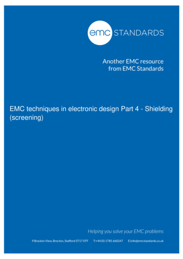
IC-EMC v2 – Application NoteA model of the Bulk Current Injection ProbeThis work has been conducted by S. Akue Boulingui and A. Cisse Ndoye within the French project“EPEA-Aerospace Valley” funded by the French Ministry of Industry.This section illustrates how to build an electrical model of the Bulk Current Injectionprobe (BCI), which is part of the international standard IEC 62132 [Ref 62132]. Wepresent the BCI probe under test, make a description of the impedance measurementset-up and describe the method for BCI probe modelling.I.BCI probe under testThe BCI test method is part of the IEC standard 62132, under reference 62132-3“Bulk Current Injection (BCI)” [1] (Table 1).StandardDescriptionStage in 2010IEC 62132-1General Conditions and DefinitionsInternational standardIEC 62132-2Radiated Immunity - TEM Cell andWideband TEM Cell MethodCommittee draft for votingIEC 62132-3Bulk Current Injection (BCI)International standardIEC 62132-4Direct RF Power Injection (DPI)International standardIEC 62132-5Work Bench Faraday Cage (WBFC)International standardIEC 62132-6Local Horn Injection Antenna (LIHA)New proposalIEC 62132-7Mode stirred chamberNew proposalIEC 62132-8Micro strip-lineNew ProposalIEC 62132-9Near field scan immunity (NFSI)New proposalTABLE I: Status of IEC 62132 standards for measurement of integrated circuit immunityThe Bulk Current Injection Probe we used is provided by ETS-Lindgren, modelnumber 95242-1 [2]. It has only one N port connexion. The probe is used to inject aradio-frequency parasitic current into conductors and cables which are connected toelectronic equipments. The probe is presented in 0. The central hole allows ouse.fr1
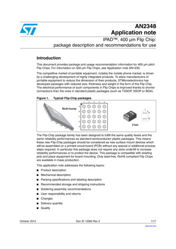
RF injection signal(N-connector)Opening sytem forcabes introductionProbe referenceTests cablesFigure 1: BCI injection probe descriptionThe BCI Probe provides a mean to inject a controlled RF stress to a device undertest (DUT) through interconnecting or power cables without requiring a directconnection to that cables. RF disturbance can be injected through a single or multiplecables, grounding and bonding straps, outer conductors of shielding conduits andcoaxial cables, etc. The bulk current injection probe series is especially designed toprovide minimum insertion loss between 2 MHz and 400 MHz (Fig. 1).II.BCI Test BenchThe BCI test bench requires at least one BCI probe, the equipment under test andthe line for power injection as shown in 0.RF sourceAmplifierLoad(s) orother deviceRF receiverLine under testInjectionprobeRF disturbancesourceLoads, electronicsystem, Deviceunder testCriterionanalysisDevice undertestFigure 2: Simple BCI test bench : principles (top) and test example (bottom).A RF source is used to generate the disturbance signal. A power amplifier increasesthe level of the signal at the desired value. The amplified signal is injected in the BCIprobe. A coupler and a RF receiver (such as a powermeter) help controlling the levelof forward power. The part of the forward power which is transferred to the deviceunder test remains unknown. To monitor the power at the far end of the cable, nearthe device under test, another BCI probe may be used as monitoring current 2
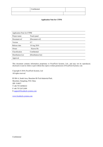
RF sourceRF receiverAmplifierLoad(s) orother deviceLine under testInjectionprobeMonitoringcurrent probeDeviceunder testFigure 3: BCI test bench with monitoring current probe.III. Impedance measurement setup and resultsBCI probe impedance over frequency is characterized through S parametermeasurements. From that measurement, we can derive an electrical model which fitsthe probe behaviour. We used a Vector Network Analyzer (VNA) and the port 1 forthe measurement (Fig. 4). The measurement system is calibrated using appropriateshort-circuit, open-circuit and 50-Ohm loads in N-connector format, so that thereference plane is at the input of the probe connector. The calibration compensatesthe cable effects, allowing the characterization of the probe impedance only.Measurementreference planeBCI probeVector NectworkAnalyzerPort 1Figure 4: S parameters measurement set-upTo download the measurements, proceed as follows:1. Click the icon “Impedance vs. frequency”2. Click “Add measurement” and select “*.s50” format3. In “EMC lib”, select the file “Meas Sparam BCI-probe fr3
4. The following screen appears. It can be seem that the coil features a very lowimpedance at low frequencies (10 Ohm around 1 MHz) and ranges between10 and 500 Ohm in the whole frequency bandwidth. The impedance profilefeatures an inductance effect ( 20 dB/decade) at low frequencies.Figure 5 : Measurement of the BCI impedance from 1kHz to 6 GHz (Meas Sparam BCIprobe 4
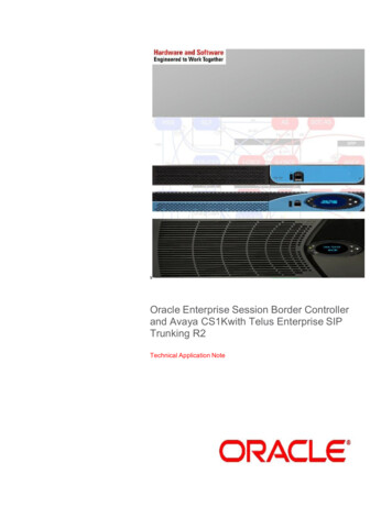
IV. First-order model of the BCI probeWe have no precise information about the internal structure of the BCI, such as theconductor width and length, number of loops, material permittivity, transformercharacteristics, etc. This does not allow us to use physical formulations in order tocalculate the corresponding impedance. We consider here the probe mainly as aninductor (0) with parasitic capacitive and resistive effects.inputFigure 6 : BCI probe internal struture1. Click « Add »2. Select « L »3. Click around here4. . or enter thevalue5. Insert thecorrespondingsymbolFigure 7 : Extraction of BCI R,L,C elements from impedance measurementTo identify the electrical equivalent elements, proceed as follow:1. In the Z(f) sub-menu, Select “Add”2. Select “L” (inductance)3. Click along the measurement curve in the 20 dB slope (1-30 MHz)4. The tool computes the equivalent L value (here: 700 nH). Alternatively, youmay enter the value and observe the 5
5. Click “Insert symbol”. A 700 nH inductance is added to the schematic diagramfor further use in the BCI modelThe resonant behaviour around 50 MHz is modelled by a RLC equivalent circuit(Erreur ! Source du renvoi introuvable.). We use a combination of L BCI 700 nH,R P 200 Ω and C P 15 pF capacitor. The serial resistance R BCI 1 Ohm ismandatory to avoid WinSpice simulation problems. As shown in Fig. 8, the schematicdiagram should also include: Connections to ground A probe symbol “Z(f)”Convert the schematic diagram into a SPICE netlist (Command and icon “GenerateSpice file”), execute the simulation using WinSpice and click the icon “ImpedanceWindow” to compare the simulated Z(f) with measured Z(f) as shown in Fig. 8 bottom.The fit is quite satisfactory upto 400 MHz.Figure 8: Schematic diagram (top) and Spice conversion (bottom) for BCI oulouse.fr6
Figure 9: A simple BCI probe model valid upto 400 MHz (BCI Model HF.sch)V.Accurate model of the BCI probe up to 6 GHzIn Figure 10 a more accurate model of the BCI probe is presented. Apart from the HFmodel described previously (L BCI, C P1, R P1), a set of R,L,C elements are addedto account for resonances around 200, 400, 900 and 4000 MHz. We propose toinclude 3 RLC cells.HF modelMaininductanceof the BCIprobeFigure 10 : BCI probe model17/05/2010etienne.sicard@insa-toulouse.fr7
Table II describes the BCI probe electrical elements. It shows extracted andoptimized values to improve the matching with measurements. The majormodification concerns L P1 and C P2.ElementL BCIC P1L P2C P2L P3C P3Extracted values0.7 uH15 pFOptimized values0.7 uH15 pFDescriptionProbe inductance valueParasitic capacitance for 50 MHzresonance19 nH6 nHParasitic inductance for 200 MHzresonance11 pF35 pFParasitic capacitance 200 MHzresonance18 nH18 nHParasitic inductance for 1 GHzresonance1.5 pF2 pFParasitic capacitance for 1 GHzresonanceTABLE II: Description of the model elementsFigure 11 shows the comparison between the measured and simulated impedance ofthe BCI probe. We can notice a very good correlation between measurement andsimulation from 1 MHz to 6 GHz.Figure 11: Comparison between measurement and simulations for the accurate model(BCI Model xHF.sch)17/05/2010etienne.sicard@insa-toulouse.fr8
VI. References[1] IEC62132-, “Integrated Circuits, Measurement of Electromagnetic Immunity, 150KHz – 1 GHz”, International Electrotechnical Commission, Geneva, Switzerland,2007 www.iec.ch[2] Datasheet: ETS Lindgreen, "Bulk Current Injection Probes manual", February2005, online: http://www.ets-lindgren.com.[3] F. Lafon, Y. Benlakhouy, F. De Daran, "Modélisation d’une pince d’injection pourle test BCI sur ligne de transmission multi conducteur", CEM 2008, Paris.17/05/2010etienne.sicard@insa-toulouse.fr9
IEC 62132-5 Work Bench Faraday Cage (WBFC) International standard IEC 62132-6 Local Horn Injection Antenna (LIHA) New proposal IEC 62132-7 Mode stirred chamber New proposal IEC 62132-8 Micro strip-line New Proposal IEC 62132-9 Near field scan immunity (NFSI) New proposal TABLE I: Status of IEC 62132 standards for measurement of integrated circuit immunity The Bulk Current