Transcription
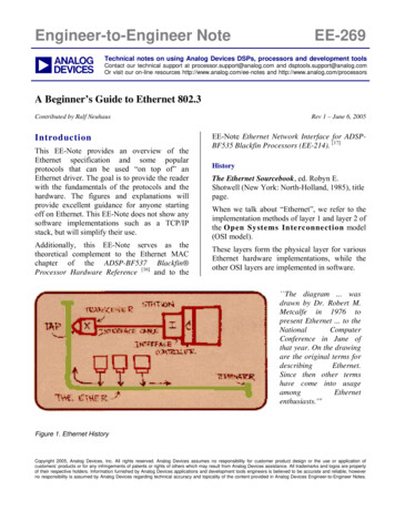
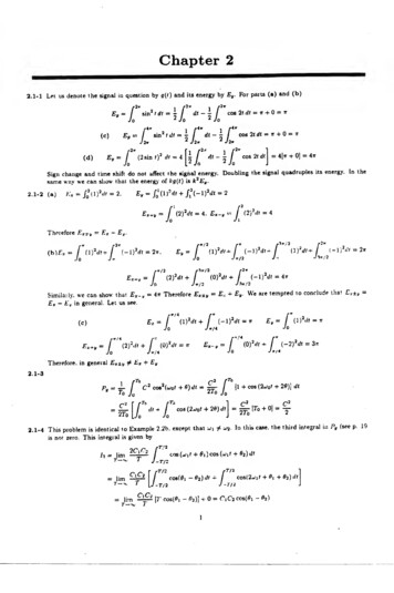
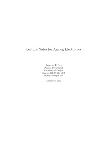
App NoteApplication Note 4FilterShop 3.0Application ManualAnalog Audio Passive CrossoverApplication Note4Analog Audio Passive CrossoverHighlightsImporting Transducer Response DataImporting Transducer Impedance DataConjugate Impedance CompensationCircuit Optimizationn Design Objective3-Way Passive Crossover200Hz/2kHz Crossover Points4th Order CrossoverOptimized ResponseImpedance Compensated TransducersThis design will provide an example ofhow to integrate many of the powerfulfeatures in the software, to produce a custom analog passive crossover network. Prototype DataWe will assume that a prototype 3-way enclosure has been constructed, similar tothat shown above, and that both SPL and Impedance data has been obtained for eachof the three sections: Woofer, Midrange, and Tweeter. This data is measured priorto the use of any crossover, and reflects the response and impedance of each sectionmeasured separately.The six graphs on the following page show the SPL and Impedance for each of thethree transducers. Both magnitude and phase is plotted for all six, and a commonfrequency range of 10Hz to 40kHz is used.Measured phase data may or may not contain the absolute position (delay)information. In this case it does not. The SPL phase measurements for each of thethree transducers are relative to the acoustic origin (voice coil) location. Consequently, we will need to handle the true time position separately.175
Analog Audio Passive Crossover100 Magnitude dB splApplication Note 4Sound Pressure LevelDeg Phase 180300Ohms Magnitude Impedance Measurement Phase 4510.0-90-135-135P25 SP25 Z2010010FreqdB spl50100 Magnitude 5001kHzSound Pressure Level5k10k40kDeg Phase 10Freq50100 Magnitude dB spl5001kHzSound Pressure Level5k10k Phase 40kDeg704560050-45-90401kHz5kImpedance Measurement10k Phase 40kDeg-180180900-451.0-90-13510.090 Magnitude 5003.018080100450.3135Ohms5010.0-18090Freq135C13 S2010C13 Z10FreqOhms50100 Magnitude 5001kHz5kImpedance Measurement10k Phase 40kDeg-180180135903.04501.0-45-900.3D25 S-135-13530D25 5001kHz5k10k40k-180FilterShop 3.0Application Manual
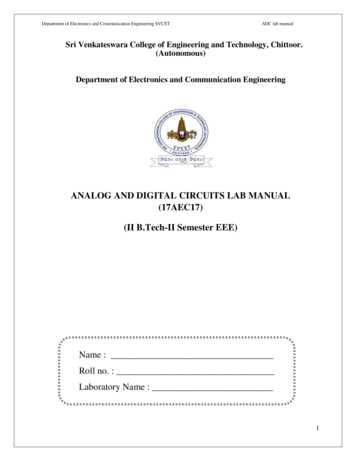
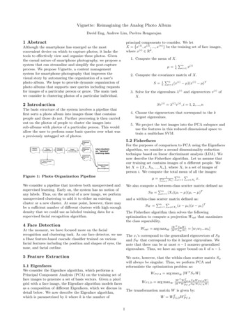
Application Note 4Analog Audio Passive Crossovern Woofer Impedance CompensationThe response of any passive network is directly affected by the loading on thenetwork. Filter networks are generally designed based on a fixed resistive load.Since the impedance of a transducer is highly complex, and certainly not fixed, acommon technique is to apply conjugate compensation. In this case the reactivecomponents are essentially cancelled by a conjugate network to yield a largelyresistive constant impedance.We start with a circuit consisting of only a Z impedance component and a generator. The woofer impedance is imported into the Z1 component, and the generatorV1 is setup for constant 1 Amp current source operation. In this manner the voltage appearing at the terminals of the load will be directly equal to the impedanceof the load.To accomplish this, the generator must have an output impedance much greaterthan the load. We shall use 1M Ohm. To produce 1 Amp of current, the voltagemust also be 1M Volt, or 120dB. The figure below displays the initial circuit setup.The Magnitude and Amplitude graphs on the following page display the resultingvoltage at the Woofer terminal, which is now equal to the impedance of the woofer.FilterShop 3.0Application Manual177
Analog Audio Passive CrossoverApplication Note 4The Magnitude graph displays the equivalent of dB Ohms (1 Ohm 0 dB),while the Amplitude graph displays linear Ohms.178FilterShop 3.0Application Manual
Application Note 4Analog Audio Passive CrossoverThe reactive impedance of the Woofer can be considered in two parts: one part isthe inductive rise at high frequencies, and the other is the double hump resonanceat low frequencies. To cancel the high frequency rise, a series resistor and capacitor shunting the load will be used.The RC shunt shown below is initially given the rough arbitrary values of 10 Ohmsand 10u Farads. The resulting impedance is shown in the Magnitude graph below.The high frequency rise has been reduced, but it is not optimal.To optimize the RC network, we must first create an objective in a Guide Curve forthe circuit optimizer to use. A flat line is the objective, but at what impedance?As an initial guess we will simply use the lowest impedancewhich occurs on the Woofercurve which is about 6.5 Ohms.An empty Target response wasused as a flat line, and then scaledto the correct level. This is shownas the gray Guide Curve flat linebelow.FilterShop 3.0Application Manual179
Analog Audio Passive CrossoverApplication Note 4Since the RC network will only be effective on the high frequency rise, wewill limit the optimizer frequency range from 150Hz to 40kHz. The RC shunthas no ability to control the double hump problem, and so the optimizer willignore this region.Average Error optimization is used, and after the optimizer has finished, theresults are shown below. The upper frequency impedance range is now nearlyflat. The RC values are 6.8 Ohms and 39u Farads.180FilterShop 3.0Application Manual
Application Note 4Analog Audio Passive CrossoverTo compensate for the double resonance hump in the lower region, a double series- parallel RLC shunt network is required. This is shown below. For initial startingvalues, the inductors are given values of 10m Henries, the capacitors are assigned1000u Farads, and the resistor set to 10 Ohms.The Magnitude graph below shows the initial combined impedance of the circuitbelow. The compensation for the double hump is not yet optimal. As before thesame objective flat line curve at 6.5 Ohms (Volts) is used, but this time the optimizer frequency range is from 10Hz to 150Hz. The previous RC values for thehigh frequency shunt are kept fixed and are not optimized.FilterShop 3.0Application Manual181
Analog Audio Passive CrossoverApplication Note 4After the optimization of the double trap network, the results below wereproduced. The double hump is now greatly reduced. It is fair to assume thatthere is some interaction between the two shunt networks. Therefore, weshould now optimize both shunts together across the entire frequency range.The results are shown on the following page.182FilterShop 3.0Application Manual
Application Note 4Analog Audio Passive CrossoverThe resulting combined impedance is very flat. To achieve a flatter impedance theobjective would need to be lowered. However, this would of course increase thepower drawn from the amplifier, with the additional power being wasted in thenetwork. There is a trade-off between the goal for flat impedance, and lowering ofthe overall impedance.The double trap network uses 20m Henry inductors. These would be rather bulkyand expensive, but can be readily obtained and/or constructed with iron or ferritecores. The two capacitors are also large around 2000u Farads, but again this is tobe expected for a network which must operate at very low frequencies.FilterShop 3.0Application Manual183
Analog Audio Passive CrossoverApplication Note 4n Midrange Impedance CompensationThe procedure for compensating the impedance reactance of the Midrangetransducer is essentially the same as that previously used for the Woofer.However in this case the low frequency resonance is a single hump. To counterthis impedance, a simple RLC series trap is used in addition to the usual highfrequency RC shunt.The objective for this transducer was reduced to about 6.0 Ohms, since itsminimum impedance was slightly lower then that of the Woofer. After thenetwork has been optimized the results are shown below.184FilterShop 3.0Application Manual
Application Note 4Analog Audio Passive Crossovern Tweeter Impedance CompensationThe procedure for compensating the impedance reactance of the Tweeter transducer is exactly the same as that previously used for the Midrange. The singleRLC resonance trap is used in parallel with the RC high frequency shunt.The objective for this transducer was reduced to about 4.5 Ohms, since its minimum impedance was lower then that of the Midrange. After the network has beenoptimized the results are shown below.FilterShop 3.0Application Manual185
Analog Audio Passive CrossoverApplication Note 4n Woofer Crossover SectionThe 4th order Lowpass section must now be designed. The corner frequencywill be set to 200Hz, and the Butterworth 6dB Allpole family will be used asa target. This family has a response which is 6dB down at the corner, andeven order LP/HP sections sum to a flat response. However, it is merely astarting point.A new design file is started, and the synthesis circuit LP04 RLC C is loaded.This is a single terminated form with only a load resistor. From our previousWoofer impedance optimization, we know that our load impedance is about6.5 Ohms. Using that load impedance as a preset value for R1, runningsynthesis produces the following LP4 section.186FilterShop 3.0Application Manual
Application Note 4Analog Audio Passive CrossoverWe can now change the circuit to custom, andimport our previous Woofer impedance circuitas the real load for the section instead of R1.The Magnitude response in the top graph below shows the ideal target and the actual circuit using the compensated transducer impedance as the load.You might be curious to know what the response would have been without impedancecompensation. By simply changing the tworesistors R1 and R2 to high values, say 6.8MOhms, we can observe the response with theraw Woofer as the load. This is shown in thelower graph.Clearly the load impedance for a passive network directly affects the response. Withoutcompensation, a peak of 9dB is produced.FilterShop 3.0Application Manual187
Analog Audio Passive CrossoverApplication Note 4n Midrange Crossover SectionThe 4th order Bandpass section must now be designed. The corner frequencies will be 200Hz and 2000Hz, and again the Butterworth 6dBAllpole family will be used as the target.Creating the Bandpass target can be easily handled by using the Flo/Fhientry method for determining the required total Q and center frequency.This is shown on the left. Loading the BP04 RLC C synthesis circuit,the initial network values were determined using the R1 preset load impedance of 6 Ohms. Then, with the Midrange transducer and compensation network substituted for R1, and the results are shown below. Theresponse is pretty close to the ideal 4th order Bandpass target.188FilterShop 3.0Application Manual
Application Note 4Analog Audio Passive Crossovern Tweeter Crossover SectionThe 4th order Highpass section must now be designed. The corner frequency willbe 2000Hz, and again the Butterworth 6dB Allpole family will be used.After starting another design file, the HP04 RLC C synthesis circuit is loaded,and the initial network values determined using the R1 preset load impedance of4.5 Ohms. Then, with the Tweeter transducer and compensation network substituted for R1 , the results are shown below. The response is very close to the ideal4th order Highpass target.FilterShop 3.0Application Manual189
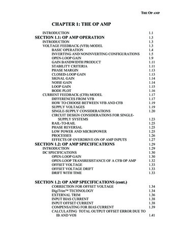
Analog Audio Passive CrossoverApplication Note 4n Adding the Transducer's Acoustic ResponseWe have now completed the electrical design of the passive networks, including compensation for the reactive impedance of the transducers. However,the transfer functions through the networks are only part of the solution. Theacoustic response of the transducers themselves must also be included. As weshall see shortly, this will dramatically alter the previous network results.Unless all of the transducers in a multiway acoustic system are coaxial mounted,an ideal crossover can only be designed for a single point in space. The drawing below illustrates the situation.We know the acoustic response foreach transducer, relative to theirBAFFLE BOARDacoustic origins, but we must alsoDvc 0.0 In (0.0 M)determine any differences in D25TweeterDvc 1.3 In (0.033 M)The Tweeter is used as the referencesince its voice coil is nearly in theplane of the baffle board. We willalso assume the Design Point is onaxis with the Tweeter, and that theoriginal SPL response for each driverwas measured at the Design Point.C13MidrangeDvc 2.3 In (0.058 M)NOTE:ANGLES NOT TO SCALE190At high frequencies, the acoustic origin of each transducer is very nearthe voice coil. This is where the conversion from electrical to acousticwave propagation takes place.P25WooferThe voice coil of the Midrange driveris back set 0.033M and the Woofer isback set 0.058M.However the total path differencebetween the drivers to the DesignPoint in space depends on the chosenreference distance, and the verticalspacing between the drivers.FilterShop 3.0Application Manual
Application Note 4Analog Audio Passive CrossoverAt very far distance, the vertical driver spacing is relatively unimportant, and thepath difference between the drivers becomes equal to the voice coil offsets. Atcloser distances the vertical driver spacing must be included in path computations.Typical reference distances are usually given as either 1 or 2 Meters for mostloudspeaker products. For this example we shall use 1 Meter as the referencedistance. We shall also assume that the vertical spacing between each driver isabout 6 Inches, or 0.15 Meters.Using basic trig the acoustic path distances are:DTWEETERDMIDRANGEDWOOFER 1 Meter sqrt( (1 0.033)2 0.152 ) 1.044 Meter sqrt( (1 0.058)2 0.302 ) 1.100 MeterTherefore the Midrange and Woofer path delay differences are:DDMIDRANGEDDWOOFER 0.044 Meter TMIDRANGE 126u Sec 0.100 Meter TWOOFER 286u Sec(Note: Speed of Sound constant 350M/Sec)The Midrange acoustic response will be delayed by 126u Sec, and the Woofer willbe delayed by 286u Sec.Another set of design files is
n Design Objective 3-Way Passive Crossover 200Hz/2kHz Crossover Points 4th Order Crossover Optimized Response Impedance Compensated Transducers This design will provide an example of how to integrate many of the powerful features in the software, to produce a cus-tom analog passive crossover network. Prototype Data