Transcription
PASSION FOR POWER.GuideDesign and assemblyaccording to IEC 61439 / EN 61439ENYSTAR Distribution Boards up to 250 A andMi Power Distribution Boards up to 630 ADownload at www.hensel-electric.de/61439
2
GUIDEDesign and assemblyaccording toIEC 61439 / EN 61439ENYSTAR Distribution Boards up to 250 A andMi Power Distribution Boards up to 630 ABasicsIEC 61439 / EN 61439Mi Power DistributionBoards4-67Step 1: Collecting all the project dataInterface characteristics of assembliesChecklist to design switchgear assemblies according to IEC 61439 / EN 61439Interface: Installation and ambient conditionsInterface: Operation and maintenanceInterface: Connection to the public power supply systemInterface: Electrical circuits and consumersStep 2: Design of an assembly and design verificationExample: Checklist to design switchgear assembliesaccording to IEC 61439 / EN 61439Project design using the data from the checklistHENSEL Planning tools at a glanceVerifications supplied by the system manufacturerVerifications to be created by the panel builder8910111213141516-171819Determining the rated short-time withstand current (Icw) of a circuit of an assemblyFeed: Determining the rated current (InA) of an assemblyRated current of an outgoing circuit (InC)Determining the operating current (IB)Calculation of the power dissipation (PV)Determining the rated diversity factor (RDF)Design verification of permissible temperature riseaccording to IEC 61439-1 / EN 61439-1 Section 10.1020-212223242526ENYGUIDE Online tool28-29Step 3: Assembly / manufacture of the distribution boardAssembly instructions for distribution board systemsRoutine verification / inspection (routine test report)30-3132-33Step 4Manufacturer's markingStep 5Declaration of EC conformity (check lists for the manufcturer of an assembly)Documentation27343536-373
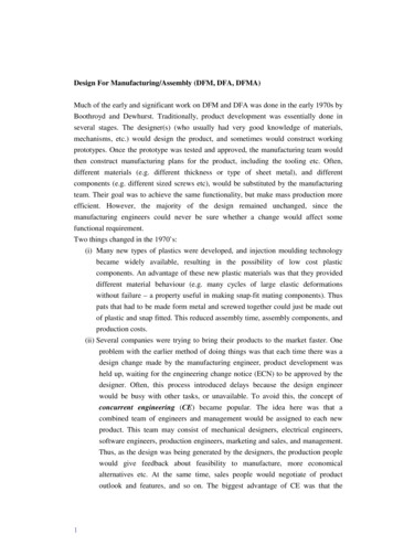
Why a guide to practice?There is a precise conformity on the content of the Standard 61439in the IEC and EN world of standards. Consequently this documentuses the writing IEC 61439 / EN 61439 in the following.IEC 61439 / EN 61439 New tasks and responsibilities for the electricianIEC 61439 / EN 61439 shows how a low-voltage switchgearassembly, which is safe for the user, can be built. In addition tochanges affecting the design of an assembly, the manufacturer of aswitchgear assembly is faced with new tasks and responsibilities.Guide 61439 for the practice:5 steps to a standard-conforming switchgear assemblyThe guide lists the process of design, assembly and documentationof a low-voltage switchgear assembly in the order of the necessarysteps and at the same time assigns to these steps the relevantsections from the standard IEC 61439 / EN 61439.The application of the guide is focused on the manufacturingof distribution boards up to 630 A and in addition to checklistsand instructions regarding the verification of compliance with themaximum temperature rise.Defines which documents belong to a low-voltage switchgearassembly and which verifications need to be maintained. Makesstatements regarding the rating of the assembly so that a designverification can be maintained.The guide can be downloaded from:wwww.hensel-electric.de/61439Step 1Collecting all the project dataStep 2Assembly design and design verificationStep 3Assembly / manufacture of the distribution boardStep 4Manufacturer's markingStep 5Declaration of CE conformity (check lists)HENSEL, as the system manufacturer, supports panel builders with this guideto design and assemble safe low-voltage switchgear assemblies according toIEC 61439 / EN 61439.4
Basics of IEC 61439 / EN 61439Legal Basis of LVD 2014/35/EU*In the European Union, theLow Voltage Directive LVD2014/35/EU forms the legalbasis for all electrical equipmentbetween 50 and 1000 V a.c., or75 and 1500 V d.c.EU onlyCompliance with this legal basis is confirmed by the declarationof conformity by the manufacturer of a switchgear assembly.Reference to EN 61439 implies that the basic requirements of thedirective have been met. If the legal requirements are not met, thepurchaser has no liability protection!If harmonized standards are not applied, the manufacturer of theswitchgear assembly has a duty to establish compliance with theabove protection objectives by appropriate means.This directive pursues the protection objective that electricalequipment must not jeopardizethe safety of persons, livestock,and the preservation of property,and refers to the harmonizedstandards, which are publishedin the Official Journal of the EU.*LVD Low Voltage DirectiveStructure of IEC 61439 / EN 61439IEC/TR 61439-0Planning guide for low-voltage switchgear assembliesIEC 61439-1 / EN 61439-1General requirements for low-voltage switchgear assembliesIEC 61439-2 / EN 61439-2IEC 61439-3 / EN 61439-3IEC 61439-4 / EN 61439-4Power switchgear andcontrolgear assembly (PSC)Distribution boards intended tobe operated by ordinary persons(DBO)ConstructionConstrConstructuctionion sisitete disdistridistributorstributbutorsorsIEC 61439-5 / EN 61439-5IEC 61439-6 / EN 61439-6IEC/TS 61439-7CableCable DisDistriDistributiontributbutionion CaCabinCabinetsbinetsetsBusbarBusbar ibutorDistributoror for cacampicamping,mping,ng, mamarkemarketrkettplaces, marinas and chargingstations for electric vehiclesIEC 61439-1 / EN 61439-1is a general part which mustbe read in conjunction withthe product sectionIEC 61439-2 to -7 /EN 61439 -2 to -7.Does not include productspecific requirements.Describes operating conditions,assembly requirements,technical properties andrequirements, as well asverification options for lowvoltage switchgear assembliesand lists the terms used.New terminology of product responsibility:Original manufacturer (system manufacturer) and manufacturerof switchgear assembly (panel builder) with new regulation forproduct responsibility.More safety through the definition of requirementsfor switchgear assemblies that affect the construction of thesystem, e.g. rated short-time withstand current, current carryingcapacity, resistance to temperature rise.More safety by determining the rating datathat are essential for the function of a switchgear assemblyunder operating conditions. For this purpose, the switchgear isconsidered as a BLACK BOX.5
Basics of IEC 61439 / EN 61439Manufacturer's product responsibilityThe manufacturer is primarily responsible for compliance with the law and the safety of a distribution board! He must provide evidence thatthe distributor was free of design, manufacturing and instruction errors when brought on the market.Thereby he must prove the safety of the assembly according to the appropriate documents (risk analysis and assessment).These documents must be retained. He must create a declaration of conformity and affix the CE marking visibly.EU onlyWho is the manufacturer of a switchgear assembly?The new standard clearly regulates the responsibility for a distribution board placed on the market. It distinguishes between the originalmanufacturer (system manufacturer) and the manufacturer of the switchgear assembly (panel builder).Panel builderPanel builderPanel builderSystem manufacturer, e.g. HENSELOriginal manufacturer (system manufacturer)Manufacturer of the switchgear assembly(Panel Builder)Responsible for:Responsible for: the thedistribution board system theverification of the design by testing, calculationor construction rules thedocumentation of this design verification,e.g. test documentation, derivations, calculationscreation of tools to design and appropriate instructions forassembling and testingrating of the switchgear assembly according to thecustomer/operator requirements thecompliance with the design verification of the originalmanufacturerthe declaration of conformity to the customer(Declaration of Conformity) theThe original manufacturer (system manufacturer) alreadyprovides the respective verifications for its distribution boardsystem.6EU only themarking and documentation of the assembly theperformance of the design verification and documentationPanel builders who have no distribution board system of theirown and assemble verified systems into ready-to-connectswitchgear assemblies thus decide for themselves about theirown verification efforts, as they can use the documents of theoriginal system manufacturer.
PORTAL 61439All about design and assemblyaccording to IEC 61439 / EN 61439With this portal, HENSEL supports you to implement the requirements of IEC 61439 / EN 61439 from the first step - collectingall project data - via the design of standard-complying HENSELdistribution board systems, up to the provision of the necessarydesign verification and routine test verification.Here you will find:Checklists and forms ENYGUIDE panning software ONLINE calculation tool for the verification of the permissible temperature riseInstructions for determining design values (InA, Inc, ICW) Technical data ALL ABOUTIEC 61439 /EN //661144339977
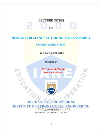
Step 1:Collecting all the project dataThe user specifies the operational requirements and conditions for alow-voltage switchgear assembly.Where special operating conditions exist that are not covered by thestandard, in addition also the applicable special requirements haveto be met or special agreements between the manufacturer of theswitchgear assembly and the user must be made. The user mustinform the manufacturer if such extraordinary conditions exist.The correct rating of the key interfaces in the switchgear assemblyis crucial for its function under operating conditions. For thispurpose, the switchgear assembly is considered a »BLACK-BOX«with four interfaces for which the manufacturer of the switchgearassembly must define the correct design values when designing theassembly.The design of the switchgear assembly is dependent on theconditions and data such as:1.1 Installation and ambient conditions1.2 Operation and maintenance1.3 Connection to the public power supply system1.4 Electrical circuits and consumersInterface characteristics of assembliesSwitchgear assembly as BLACK BOX with the 4 interfaces according to IEC 61439 / EN 614391.1Conditions at place ofinstallation/environment1.2 Operation and maintenance- Installation site- Special requirements foruse in commercial andindustrial applications- Access and operation only byskilled persons (electricians)- (Device) operation by ordinarypersons - unskilled personsBLACK BOXENYSTARCombinable enclosuresystem, insulationenclosed, totallyinsulated, IP 66,for the assembly ofdistribution boardsup to 250 A intended tobe operated by ordinarypersons (DBO) accordingto IEC/EN 61439-3Mi DistributorCombinable enclosuresystem, insulationenclosed, totallyinsulated, IP 65,for the assembly ofpower switchgear andcontrolgear assemblies(PSC) to 630 Ain accordance withIEC/EN 61439-21.3Connection to the publicpower supply system1.4Electrical circuits and consumers- Nominal data of the feed- Nominal values transformer- Short-time withstandcurrent- Determination of the thermalpower dissipation8- Rating of outgoing circuits- Determination of the rated diversityfactor (RDF)
Step 1:Collecting all the project dataHENSEL checklist to design switchgear assemblies according to IEC 61439 / EN 61439The checklist to design switchgear assemblies according toIEC 61439 / EN 61439 can be quickly and easily downloaded.This editable checklist supports you in step 1 when collecting alldata for the design of a distribution board on site.It reflects the determination of the correct design values for the fourinterfaces of the assembly.wwww.hensel-electric.de/61439Checklist to design switchgear assembliesin accordance with IEC 61439 / EN 61439 Request/OfferHensel il:1. Installation and ambient conditions1.1 Installation andambient conditionsPage 10Type of business:- indoors: in the locked electrical operation room in production area- outdoors: protected outdoors unprotected outdoorsAvailable wall surface in mm:Width: Height:Depth: wall-mounted floor-standingAssembly type:Degree of protection: IP 44 IP 54 IP 552. Operation1.2 Operation and maintenancePage 11Indoor/ambient temperature ( C):Installation IP 65 by skilled persons (electricians) IP by unskilled persons opaque/without inspection pane transparent/with inspection pane Doors/lids:3. Connection to the public power supply system1.3 Connection to the publicpower supply systemPage 12Main distribution board: Outgoing device:Transformer: Rated power (kVA):Impedance uk (%): 4 V a.c. V d.c. HzRated voltageConductor designation: L1, L2, L3 N I IIProtection class:Incoming device: 6 Rated current (A): PE PENConnection incoming: from top from bottom copper aluminum with cable lug with terminal conductor single conductor from left from right cross section (mm²):4. Electrical circuits and consumers1.4 Electrical circuits andconsumersPage 13Connection outgoing: from top from bottom from left connected to device via terminal blocks from right cross section (mm²):Equipped with:QuantityType of protective device(fuse, circuit breaker, .)Rated values of theconsumer(current, power, Gustav Hensel GmbH & Co. KG Industrial Electrical Power Distribution Systems D 57368 Lennestadt Germany www.hensel-electric.de/614399
Step 1:Collecting all the project data1.1 Installation / ambient conditionsThe checklist queries these installation and ambient conditions onsite, which need to be provided by the planner. The manufacturerconsiders this information and assembles the distributionboard according to these requirements. The measures andrecommendations given must be considered for the safe operationof the distribution board.1. Installation / ambient conditionsType of business: Indoor / ambient temperature ( C):InstallationIndoor: in locked electrical operating room in production areaOutdoors: protected outdoors unprotected outdoorsAvailable wall surface in mm: Width:Assembly type:Height:Depth: wall-mounted floor-standingDegree of protection: IP 44 IP 54 IP 55 IP 65 IPType of businessTake into account special requirements for use in commercial and industrial applications, such as strongmechanical and chemical stress on assembly material.Room / ambienttemperature ( C) accordingto IEC 61439 / EN 61439Temperature range: -5 C to 35 C, max. 40 CHumidity: 50% at 40 C, 100% at 25 CMeasures: Specify power dissipation of the assembly for the rating of the ventilation / room size.Higher ambient temperatures must be considered in planning.Installation indoorsIn locked electrical operating room: Only accessible by skilled persons (electricians)During operation: Accessibility by unskilled personsIP degree of protectionProtection against foreign bodies: dust-proof IP 6XWater protection: waterproof IP X6 / IP X5 (deflected water without high pressure)Installation outdoors- Protected outdoors- Unprotected outdoorsDirect sunlightThe material has been tested for UV resistance.UV-resistant according to IEC 61439-1 / EN 61439-1 paragraph 10.2.4.If necessary, protect with additional measures against direct sunlight, for example with canopyTemperature and humidityHigher ambient temperatures, possibly due to direct sunlight have to be considered in the planningstage.IP degree of protection for protected or unprotected outdoor installationWhere appropriate, consider measures against occasional condensation forming as a result oftemperature variations, such as venting, heating, air-conditioning (also with unprotected installation).Type of installationSpecify the system type for wall-mounting or floor-standing installationAvailable sizesConsider installation conditions on site and specify restrictions as needed.For details, see HENSEL main catalogue or www.hensel-electric.de.10
Step 1:Collecting all the project data1.2 Operation and maintenanceThe checklist queries the necessary requirements for the switchgearassembly for the operation taking into account the qualificationsof persons who require access to the respective areas or mustoperate equipment.2. OperationDoors/lids:Operation by by skilled persons (electricians) by unskilled person opaque/without inspection pane transparent/with inspection pane Electrician (skilled person)IP XXBDevices which must be operated by a qualified electrician only,shall be installed behind separate doors or lids which can beopened with a tool only.Tool-operated areas for feeding-in, back-up fuse and outgoingterminals.Here, merely a qualified electrician must have access!Electrically trained personIP XXB, see qualified electricianElectro-technical unskilledpersonSelection of equipment forunskilled persons!Only installation devices such asseries built-in equipment, fusesup to 63A, circuit-breakers andIT components permitted.IP XXC: Protection against direct contact with hazardous live partsFor distribution boards, IEC 61439-3 / EN 61439-3 requires specialprotective measures for areas to which unskilled persons haveaccess:- Live parts should be covered with a protection cover.- Devices which may be operated by a qualified electrician only,shall be installed behind separate lids or doors, which can beopened only with a tool.Hand-operation for the access areas of unskilled persons or use ofhinged lids allowing easy control of equipment.Devices operatedDoors / coversBehind the door / lidProtection measures must be observedLock available for retrofittingConversion kits for door or lid fasteners from hand to tool operationavailableFor details, see HENSEL main catalogue or www.hensel-electric.de.11
Step 1:Collecting all the project data1.3 Connection to the public power supply systemThe checklist describes the required features of the network(nominal data). These must be compared with the design data ofthe low-voltage switchgear assembly.For the planning of a switchgear assembly, the necessary ratedvalues of the grid must be determined and specified.3. Connection to the public power supply systemMain distribution board: Outgoing device:Transformer: Rated power (kVA):Impedance uk (%): 4 6Rated voltage V a.c. V d.c. Hz Rated current (A):Conductor designation: L1, L2, L3 NProtection class: I IIIncoming device:Connection incoming: from top from bottom copper alumini with cable lug with terminal conductor single conductor PE PEN from left from right cross section (mm²):Rated voltage of the feedin VAC a.c., HzGrid systemTN-C, TN-C-S, TN-S, TT, ITProtection class II, protection by protective insulationRated currentInfeed current (rated currenttransformer / upstream protectivedevice)Determine InA, see step 2, design of a distribution board, page 22Short-circuit resistanceDerive value from the size of thetransformer or use the informationfrom the local power supplierExample calculation see pages 20-21.IcpIK"For detailed information about- determination of the rated current (InA)- determination of the rated short-timewithstand current (ICW)OvervoltageOvervoltage category III, IVIncoming cable connectionType of incoming cableType of cableType of connection12Page 22Page 20-21
Step 1:Collecting all the project data1.4 Electrical circuits and consumersOutgoing circuits in a switchgear assembly can be distinguishedinto distribution circuits (protective device and incoming cable todownstream distribution) and final circuits (protection device andincoming cable and consumers).For a correct rating of the circuits, all information regardingthe expected power demand and consumers must be known.Therefore, the technical data of the device manufacturer withinformation on derating, but also the rated current of a circuit andthe rated diversity factor RDF must be considered.4. Electrical circuits and consumersConnection outgoing: from top from bottom connected to device via terminal blockEquipped with from left from right cross section (mm²):Quan-Type of protective deviceRated values of the consumertity(fuse, circuit breakers, .)(current, power, Outgoing cableconnectionType of outgoing cableType of cableType of connectionEquippingType of protective deviceFuse, miniature circuit breaker,circuit breakerRating data of theconsumerCurrentPowerType (ohmic, inductive or capacitiveload) cos For detailed information about- Rating of an outgoing circuit (InC)- Determination of the operating current (IB)- Calculation of the power dissipation (PV)- Creating the design verification of thepermissible temperature rise according toIEC 61439-1 / EN 61439-1 Section 10.10.Page 23Page 24Page 25Page 2613
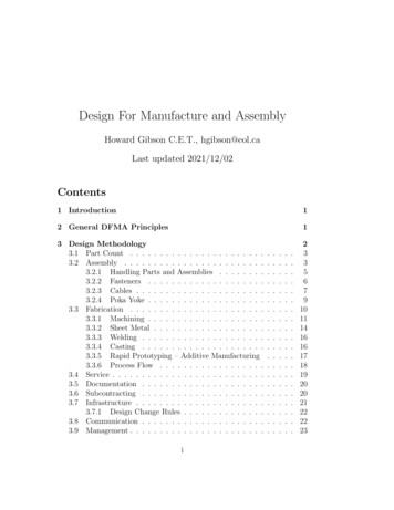
Step 2:Design of an assembly and design verificationExample: Checklist to design switchgear assemblies according to IEC 61439 / EN 61439Collecting the data on-site withthe checklist forms the basisto design a distribution board.Checklist to design switchgear assembliesin accordance with IEC 61439 / EN 61439HoffmannHensel expert: dress:Metal working shop BrandsMusterstraße 1050000 MusterstadtExtension to the production facilitySection IIPhone:E-Mail:info@ brands-metalworkingshop.de1. Installation and ambient conditionsMetal working shop Indoor/ambient temperature ( C):25Type of business:Installation- indoors: in the locked electrical operation room X in production area- outdoors: protected outdoors unprotected outdoors15001400Width:Height:Available wall surface in mm:500Depth: X wall-mounted floor-standingAssembly type:Degree of protection: IP 44 IP 54 X IP 552. Operation IP 65 by skilled persons (electricians) IP by unskilled personsX transparent/with inspection pane X opaque/without inspection pane XDoors/lids:3. Connection to the public power supply systemMain distribution board: Outgoing device:Transformer: Rated power (kVA):Impedance uk (%): 4230/400 50 HzX V a.c. V d.c. Rated voltageConductor designation: L1,L2, L3X NX I IIXProtection class: 6 400Rated current (A): PE PENXCircuitbreakerIncoming device:Connection incoming: from top from bottomX X copper aluminum with cable lug X with terminal conductor single conductor from left from right 4x150/70cross section (mm²):4. Electrical circuits and consumersConnection outgoing: from top X from bottom from left X connected to device via terminal blocks from right cross section (mm²):Equipped with:QuantityType of protective device(fuse, circuit breaker, .)Rated values of theconsumer(current, power, .)CommentsConsumer1MCCB200 AMachine IConsumer1MCCB128 AMachine IIConsumer1MCCB128 AInternal fuseConsumer1RCBO63 AInternal protection for MCBsConsumer14MCB12 ALight and socket outletsGustav Hensel GmbH & Co. KG Industrial Electrical Power Distribution Systems D 57368 Lennestadt Germany www.hensel-electric.de/61439DDownloadeditable checklist:www.hensel-electric.de/61439w14
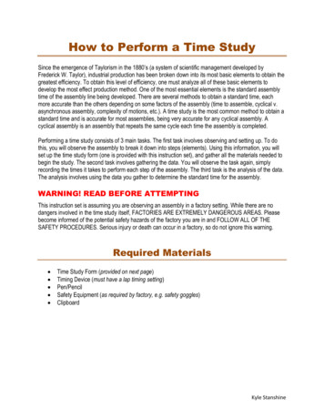
Example: Project design using the data from the checklistBy complying with the information from catalogues, technicalmanuals and installation instructions, the effort required by the panelbuilder for providing the design verification is minimized.I 3-Q3160AI A circuit diagram results fromthe determined data from thechecklist, which defines theelectrical functions.23-Q4100AI hnecnologiennMi Distribution BoardHRC fuse boxes with fuse switch disconnectorswith fuse switch disconnectors in accordance with IEC 60 947-3Mi 626632 Wall 232 x fuse switch disconnector 160 A,HRC 00, 3-poleRated current of busbars 400 Aonly for combination300170300DKfor outgoing cables: 4-35 mm², Cu, round conductorsper PE and N terminal: 2 x 4-35 mm², Cu, round conductorssupply cableconductor with the same current carrying capacity as the phaseconductorsconnections from the top, changeable to bottom connections with cover Lid fasteners for tool operation without N CableMiCentreline spacing of busbarsTightening torque for terminalCentreline spacing of busbarsTightening torque for terminal32 Wall 232 x fuse switch disconnector 160 A,HRC 00, 3-poleRated current of busbars 630 Aonly for combination330Un 690 V a.c.Inc 128 A2ICW 21 kA / 1 swith fuse links utilisationcategory gG/gL5L1-L3, N, PE: 10 mm60 mmterminal 6.0 Nm600300170Un 690 V a.c.Inc 128 A2ICW 15 kA / 1 swith fuse links utilisationcategory gG/gL5L1-L3: 10 mmN, PE: 5 mm60 mmterminal 6.0 NmMi 642752 Wall 352 x fuse switch disconnector 160 A,HRC 00, 3-poleRated current of busbars 400 Afor incoming cables: 25-70 mm², Cu, round conductorsConnection of wiring strip Mi VS 100/160/250/400for outgoing cables: 4-35 mm², Cu, round conductorsper PE and N terminal: 2 x 4-35 mm², Cu, round conductors N conductor with the same current carrying capacity as the phaseconductors Cable connections from the top, changeable to bottom connections with cover Lid fasteners for tool operation300 TerminalsRated voltageRated current of a circuitNumber of circuitsRated short-time withstandcurrentBusbar system - polarityBusbar thicknessCentreline spacing of busbarsTightening torque for terminal170NPE Terminals TerminalsRated voltageRated current of a circuitNumber of circuitsRated short-time withstandcurrentfor incoming cables: 25-70 mm², Cu, round conductorsConnection of wiring strip Mi VS 100/160/250/400 Terminals for outgoing cables: 4-35 mm², Cu, round conductorsper PE and N terminal: 2 x 4-35 mm², Cu, round conductors N conductor with the same current carrying capacity as the phaseconductors Cable connections from the top, changeable to bottom connections with cover Lid fasteners for tool operationBusbar system - polarityBusbar thicknessMi 6267Busbar system - polarityBusbar thicknessCentreline spacing of busbarsTightening torque for terminal52 Wall 352 x fuse switch disconnector 160 A,HRC 00, 3-poleRated current of busbars 250 ARated voltageRated current of a circuitNumber of circuitsRated short-time withstandcurrentUn 690 V a.c.Inc 128 A2ICW 15 kA / 1 swith fuse links utilisationcategory gG/gL5L1-L3, N: 10 mmPE: 5 mm60 mmterminal 6.0 Nmfor outgoing cables: 4-35 mm², Cu, round conductorsper PE and N terminal: 2 x 4-35 mm², Cu, round conductors without supply cable N conductor with the same current carrying capacity as the phaseconductors Cable connections from the top, changeable to bottom connections with cover Lid fasteners for tool operationMi 6426 Terminals TerminalsBusbar system - polarityBusbar thicknessNo. 16L,N,PEA2Mi Distribution BoardHRC fuse boxes with fuse switch disconnectorswith fuse switch disconnectors in accordance with IEC 60 947-3Rated voltageRated current of a circuitNumber of circuitsRated short-time withstandcurrentINTERNATIONAL CATALOGUEController-K7 L1-L3,N,PEA1-F5.12B16APASSION FOR 50ADKDKI Mi3-Q1400ASelection ofproducts forthe electricalfunctions.3001L1-L3,N,PE - 400/230V 400A600mmadead in GERMANYsince 1931170N300The design is realized on basis of documents, catalogues, andtechnical data provided by HENSEL, as the original manufacturer(system manufacturer).PEUn 690 V a.c.Inc 128 A2ICW 15 kA / 1 swith fuse links utilisationcategory gG/gL5L1-L3, N: 10 mmPE: 5 mm60 mmterminal 6.0 Nm331Selection of products for the electrical functions from manufacturers'catalogues or with the planning tool ENYGUIDE.4At the end of the design,a dimensional drawing and aparts list must be created for thedistributor.HENSEL providescomprehensive planning toolsthat simplify the planning.15
Step 2:Design of an assembly and design verificationPlan quickly and easily with the HENSEL planning toolsYour planning is significantly simplified by the use of the HENSEL planning tools.The functions of the different planning tools are provided here in comparison.rated currentrated currentFuse base on busbarNH 00NH 1Mi Distribution BoardHRC fuse boxes with fuse switch disconnectorsmounting plateor ondisconnectwith fuse switch disconnectors in accordanceIEC 60947-3Fuse switchwithNH 1Mi 6266Mi 5.NH 2Mi 5.NH 3Mi 5.Mi 5.300170-300Mifor outgoing cables: 4-35 mm², Cu, round conductorsdisconnectorSwitchper PE and N terminal: 2 x 4-35 mm², Cu, round conductors5101, FP 5103Mi 7103, Mi 7104, FP without supply cable5104 N conductor with the same current carrying capacity asMiMi 7214, FP 5102, FPthephase7213,conductorsFP 5201, FP 5202 Cable connections from the top, changeable to bottom connectionsMi 7457Mi 7256, Mi 7257, Mi 7456,with cover-Centreline spacing of busbarsTightening torque for terminalFP 5211, FP 5213Mi 7454, FP 5312Un 690 V a.c.Mi 7455,Inc 128 A Mi 7445, Mi 78462Mi 7665, Mi 7865, Mi 78667,3 W2 x fuse switch disconnector160 A,HRC 00, 3-poleRated current of busbars 250 ANH 252 Wall 35ICW 15 kA / 1 swith fuse links utilisationcategory gG/gL5L1-L3: 10 mmN, PE: 5 mm60 mmterminal 6.0 Nm4,6 W160 A160 A160 ADIIDIID025,9 W5,9 W5,9 W250 A8,6 W400 A15,0 W25 A0,4MiWDistribution25 AW0,4Technical63 AW3,3PowerBoardsDetailsDissipation of Empty Boxes3,3 W63 A2,0 WTemperature rise63(Δ-)boardsA with Mi-Distributionby power dissipation of electricaldevices2,0 W63 A2,0 W63 A63 AExternal enclosuresRatedcurrent ofbusbarsSize522 x fuse switch disconnector 160 A,HRC 00, 3-poleRated current of busbars 400 A3,5 WPowerdissipationof busbars atrated current35250 Afor incoming cables: 25-70 mm², Cu, round conductorsConnection of wiring strip Mi VS 100/160/250/400 Terminals for outgoing cables: 4-35 mm², Cu, round conductorsper PE and N terminal: 2 x 4-35 mm², Cu, round conductors N conductor with the same current carrying capacity as the phaseconductors Cable connections from the top, changeable to bottom connectionsTightening with cover Lid fasteners for tool operation600170N42,7 W/m400 A63,8
Step 2: Design of an assembly and design verifi cation Example: Checklist to design switchgear assemblies according to IEC 61439 / EN 61439 14 Project design using the data from the checklist 15 HENSEL Planning tools at a glance 16-17 Verifi cations supplied by the system manufacturer 18 Verifi cations to be created by the panel builder 19