Transcription
Michelin Aircraft Tirecare & servicemanual
MICHELIN AIRCRAFT TIRECARE AND SERVICE MANUALForMICHELIN AIRCRAFT TIRES AND TUBESCommercialRegionalGeneral AviationMilitaryDocumentRevisionDateMAT-CSM 32-45-01E1 January 2016The information contained herein is PROPRIETARY to Michelin. It is intended for thebenefit and use of owners and maintenance personnel of Michelin Aircraft Tires.Contact Michelin for reproduction authorization.Reproduction for other commercial purpose is not permitted.Important Note: Any copy of this document may not be the updated document currently in effect.The current version is located on the Michelin aircraft tire website: www.airmichelin.com.MAT-CSM 32-45-01 Revision E32-45-01Title Page 1Revision: 1 January 2016
This document, MAT-CSM 32-45-01, Revision E supersedesall previous Aircraft Tire Care and Service Manuals.Revision History:DocumentRevisionDateMAT-CSM 32-45-01D2012MAT-CSM 01C2001MAT-CSM 95B1995MAT-CSM 95A1995MAINT-0013Original1991MAT-CSM 32-45-01 Revision E32-45-01Title Page 2Revision: 1 January 2016
MICHELINAIRCRAFT TIRECARE AND SERVICE MANUALTABLE OF CONTENTSSUBJECT TITLEPAGEINTRODUCTION11.General12.Installation Approval13.Warnings for the Full Manual14.Related Source Documents25.Related Source Organizations26.Michelin Contacts37.Cage Code4CHAPTER 1 AIRCRAFT TIRE DESCRIPTION/CONSTRUCTION1011.General1012.Tire Zones1023.Aircraft Tire Construction (Bias and Radial)4.103 104 Components Unique to MICHELIN Radial Aircraft Tires5.Components Unique to MICHELIN Bias Aircraft Tires1056.Sidewall Venting1077.Chine Tires109CHAPTER 2 AIRCRAFT TIRE TERMINOLOGY AND TIRE MARKINGS (Branding)2011.Tire Terminology2012.Tire Sizes2013.Tire Markings (Branding)2024.Retread Markings2115.Tube Markings213CHAPTER 3 RECEIVING AND STORING3011.Handling of Tires and Tubes3012.Storage of Unmounted Tires and Tubes303CHAPTER 4 MOUNTING INSTRUCTIONS (Assembly)4011.WARNINGS and NOTES for This Chapter4012.Materials4023.Tools, Fixtures and Equipment4034.Pre-Assembly Checklist for the Tire/Wheel Assembly (Hub)4045.Mounting (Assembly) – Tubeless Tires4076.Mounting (Assembly) – Tube-Type Tires4097.Inflation of a Tire/Wheel Assembly to Operational Pressure411MAT-CSM 32-45-01 Revision E32-45-01Table of Contents: Page 1 of 2Revision: 1 January 2016
MICHELINAIRCRAFT TIRECARE AND SERVICE MANUALTABLE OF CONTENTSCHAPTER 4 MOUNTING INSTRUCTIONS (Assembly) Continued8.Pressure Retention Check (Leak Check) – After Mounting4129.Investigation for the Cause of Pressure Loss41910.Transportation of an Inflated Tire/Wheel Assembly42011.Storage of an Inflated Tire/Wheel Assembly42112.Periodic Re-inspection of an Inflated Tire42213.Mounting the Tire/Wheel Assembly on the Aircraft422CHAPTER 5 OPERATION ON AIRCRAFT5011.Proper Inflation Pressure Maintenance5012.WARNINGS, CAUTIONS, and NOTES for This Chapter5013.Pressure Checks5024.Measure the Pressure When Tires Are “Cold”5035.Maintenance Action5046.Hot Tire Pressure Checks5067.Normal Wear Removal Criteria5068.Tire Damage to the Tread5089.Tire Damage to the Sidewall52110.Operating Conditions and Considerations52511.Matching and Mixability of Aircraft Tires53012.Tire Creep53113.Static Discharge53114.Tire Marking Tools53215.Military Arresting Cables532CHAPTER 6 DISMOUNTING (Disassembly)6011.General6012.WARNINGS and CAUTIONS for This Chapter6013.Track the Reasons for Tire Removal6014.Tools, Fixtures, and Equipment6025.Disassembly (Dismounting) of the Tire From the Wheel6066.Troubleshooting Disassembly (Dismounting) Issues6097.Tire Inspection After Dismounting611CHAPTER 7 RETREAD/REPAIR7011.General7012.Retreading Aircraft Tires7023.Repairing Aircraft Tires702MAT-CSM 32-45-01 Revision E32-45-01Table of Contents: Page 2 of 2Revision: 1 January 2016
MICHELINAIRCRAFT TIRECARE AND SERVICE MANUALINTRODUCTION1. GeneralThis manual is presented as a guide to help aircraft owners and maintenance personnel obtain maximumservice life from their MICHELIN aircraft tires. Unless specifically noted otherwise, it applies to radialand bias tires, both new and retreaded. Topics include: Aircraft tire description and terminology Storage and handling Mounting, inflation, and dismounting In-service procedures including inflation pressure maintenance Troubleshooting guidelinesThis manual is intended to supplement the specific instructions issued by aircraft and wheelmanufacturers. These include the Pilot’s Operating Handbook/Airplane Flight Manual (POH/AFM),Aircraft Maintenance Manuals (AMM), and Component Maintenance Manuals (CMM). Any user ofthis manual who finds an apparent conflict between this manual and manufacturer guidelines shouldcontact their Michelin representative.The use of MICHELIN Aircraft tires on ground vehicles is not recommended. Aircraft tires are designedand manufactured for use only on aircraft. Michelin shall not be responsible for any loss or damagecaused by unauthorized use of MICHELIN Aircraft tires.Carefully read and obey all WARNING and CAUTION statements given in this manual. A WARNING is given to prevent personal injury or when an action can affect safety of flight. A CAUTION is given to prevent damage to equipment or parts. A NOTE is used to provide information to make a task easier.2. Installation ApprovalThe existence of an Airworthiness approval does not automatically constitute the authority to installand use the tire on an airplane. The conditions and tests required for Airworthiness approval of anaircraft tire are minimum performance standards. It is the responsibility of those desiring to install anaircraft tire on a specific type or class of airplane to determine that the airplane operating conditionsare within the capacity of the tire demonstrated in accordance with the Airworthiness Standards.3. Warnings for the Full ManualWARNING: AIRCRAFT TIRE AND WHEEL ASSEMBLIES MAY OPERATE UNDER HIGH PRESSURES IN ORDERTO CARRY THE LOADS IMPOSED ON THEM. THEY SHOULD BE TREATED WITH THE SAME RESPECT THATANY OTHER HIGH PRESSURE VESSEL WOULD BE GIVEN.WARNING: AIRCRAFT TIRES IN AMBIENT TEMPERATURE CAN BE OPERATED UP TO OR AT RATEDINFLATION PRESSURE. EXTREMELY HIGH INFLATION PRESSURES MAY CAUSE THE AIRCRAFT WHEEL ORTIRE TO EXPLODE OR BURST, WHICH MAY RESULT IN SERIOUS OR FATAL BODILY INJURY.WARNING: AIRCRAFT TIRES MUST ALWAYS BE INFLATED WITH A PROPERLY REGULATED INFLATIONSOURCE. INFLATING WITHOUT A PRESSURE REGULATOR PRESENTS A RISK OF PERSONAL INJURY AND/OR DAMAGE TO EQUIPMENT. DIRECT HIGH PRESSURE SHOULD NEVER BE USED. EXTREMELY HIGHINFLATION PRESSURES MAY CAUSE THE AIRCRAFT WHEEL OR TIRE TO EXPLODE OR BURST, WHICH MAYRESULT IN SERIOUS OR FATAL BODILY INJURY.MAT-CSM 32-45-01 Revision E32-45-01Introduction: Page 1 of 4Revision: 1 January 2016
MICHELINAIRCRAFT TIRECARE AND SERVICE MANUALINTRODUCTION4. Related Source Documents4.1.Title 14 of the Code of Federal Regulations (14 CFR)4.1.1. Part 21, subpart O, Technical Standard Order Authorizations4.2.FAA AC 145-4A, Inspection, Retread, Repair and Alterations of Aircraft Tires4.3.Technical Standard Orders4.3.1. FAA TSO-C62 (current), Aircraft Tires4.3.2. ETSO-C62 (current), Aircraft Tires4.4.Airworthiness Directives4.4.1. AD 87-08-09, Airbus Industrie, Boeing, British Aerospace, Lockheed, McDonnell Douglas;Specified Models4.5.Industry Documents4.5.1. RMA Aircraft Tire Service Bulletins4.5.1.1. Aircraft Tire Recommended Operating Inflation Pressure Maintenance Criteria4.5.1.2. Use of Aircraft Tires and Wheels in Other Than Aircraft Service4.5.1.3. Aircraft Tire and Tube Storage Recommendations4.5.1.4. Aircraft Tire Bursts4.5.1.5. Aircraft Tire/Wheel Compatibility4.5.1.6. Interchangeability/Mixing of Aircraft Radial and Bias Tires4.5.1.7. Aircraft Tire Conductivity4.5.2. SAE-ARP 4834, Aircraft Tire Retreading Practice – Bias and Radial4.5.3. SAE-ARP 5265, Minimum Operational and Maintenance Responsibilities for Aircraft Tire Usage4.5.4. SAE-ARP 6225, Aircraft Tire Inspection – In-Service Removal Criteria5. Related Source OrganizationsThe European Tyre and Rim Technical Organisation (ETRTO) (www.etrto.org)The Tire and Rim Association, Inc. (T&RA) (www.us-tra.org)Rubber Manufacturers Association (RMA) (www.rma.org)SAE International (www.sae.org)MAT-CSM 32-45-01 Revision E32-45-01Introduction: Page 2 of 4Revision: 1 January 2016
MICHELINAIRCRAFT TIRECARE AND SERVICE MANUALINTRODUCTION6. Michelin Contacts6.1.6.2.World Headquarters6.1.1. Michelin Aircraft Tyre23, Place des Carmes-Dechaux63040 Clermont-Ferrand Cedex 9FranceCommercial Offices6.2.1. North, Central and South AmericaMichelin Aircraft Tire CompanyOne Parkway SouthGreenville, SC 29615U.S.A.6.2.2. Europe, CIS, Middle East, AfricaMichelin Aircraft Tyre23, Place des Carmes-Dechaux63040 Clermont-Ferrand Cedex 9France6.2.3. Far East and OceaniaMichelin Siam Co.Aircraft Tyre OperationsSPE Tower 11th Floor252 Phaholyothin RoadSamsaen Nai, PayathaiBangkok 10400ThailandNOTE:For more information, visit http://airmichelin.comMAT-CSM 32-45-01 Revision E32-45-01Introduction: Page 3 of 4Revision: 1 January 2016
MICHELINAIRCRAFT TIRECARE AND SERVICE MANUALINTRODUCTION7. Cage CodeCAGE CODEF06350A1K8SGV30Manufacture Française DesPneumatiques MichelinMichelin North AmericaDBA Michelin Aircraft Tire CompanyMichelin Siam Group Co.Michelin Aircraft Tyre23, Place des Carmes-Dechaux63040 Clermont-Ferrand Cedex 9FranceMichelin Aircraft Tire CompanyOne Parkway SouthGreenville, SC 29615U.S.A.Michelin Siam Co.Aircraft Tyre OperationsSPE Tower 11th Floor252 Phaholyothin RoadSamsaen Nai, PayathaiBangkok 10400ThailandNOTE: For more information, visit http://airmichelin.comMAT-CSM 32-45-01 Revision E32-45-01Introduction: Page 4 of 4Revision: 1 January 2016
CHAPTER 1 - AIRCRAFT TIRE DESCRIPTION/CONSTRUCTION1. General1.1.An aircraft tire must withstand a wide range of operational conditions. While on the ground, it mustsupport the weight of the aircraft. During taxi, it must provide a stable, cushioned ride while resistingheat generation, abrasion, and wear. During take-off, the tire structure must be able to endure not onlythe aircraft load, but also the forces generated at high angular velocities. Landing requires the tire toabsorb impact shocks while also transmitting high dynamic braking loads to the ground. All of thismust be accomplished while providing a long and reliable service life.1.2.These extreme demands require a tire that is highly engineered and precisely manufactured. The tire isa composite of a number of different rubber compounds, fabric material and steel. Each component andrubber compound serves a specific purpose in the performance of the tire.1.2.1.All MICHELIN manufactured aircraft tires are certified for in-service operation to-55 C (-67 F) ambient.1.3.Two different and distinct aircraft tire constructions are produced and provided on the market.Both nomenclatures describe the differences in casing construction.1.3.1. The Bias tire (cross-ply construction).1.3.2. The Radial tire.1.4.Many of the components of bias and radial tires have the same terminology. However, the technologiesand process assemblies utilized are quite different requiring different design parameters, compounds,and materials.1.5.This chapter describes the different components that make up the construction of an aircraft tire.Understanding these components and their purpose will help with the understanding of the MICHELINAircraft Tire Care and Service Manual and the recommendations contained herein.1.6.While the technologies between bias tire and radial tire perform very differently, their in-servicemaintenance procedures and removal limit criteria remain similar.1.7.An aircraft tire is received as a complete component.NOTE: A visual inspection of the tire is required to assure no handling damage has occurredduring transport.1.8.The tire must be mounted on a wheel to form a tire/wheel assembly prior to service use.NOTE: Refer to Chapter 4 – MOUNTING INSTRUCTIONS (Assembly), in this manual.1.9.Many aircraft tires are designed to be retreaded. Retreading is the process of renewing the treadproducts of the tire allowing the casings to be used multiple times. Tires damaged in service may also berepairable. Retreading and repairing extends the service life of a casing, reducing operational costs andminimizing environmental impact. Refer to Chapter 7, RETREAD/REPAIR.1.10. The FAA, EASA and regulatory organizations in other countries require that retreading and/or repair ofaircraft tires be performed only by a certified facility. The certification is determined by thegoverning authority under which the operator is authorized.1.11. Michelin meets or exceeds all testing requirements of the FAA/EASA for retreaded aircraft tires.MAT-CSM 32-45-01 Revision E32-45-01Description/Construction: Page 101 of 110Revision: 1 January 2016101MICHELINAIRCRAFT TIRECARE AND SERVICE MANUAL
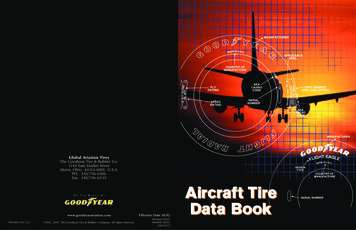
102MICHELINAIRCRAFT TIRECARE AND SERVICE MANUALCHAPTER 1 - AIRCRAFT TIRE DESCRIPTION/CONSTRUCTION2. Tire ZonesFigure below describes the different zones of a tire.Bead HeelSidewallTreadBead Flange Area(Bead Bearing Area)InnerlinerBead FlatBeadBead ToeShoulderFigure 101. Tire Zones and Tire Bead Zones2.1.The Tread or Crown Zone extends from the shoulder on one side of the tire to the opposite shoulder side.2.2.The Shoulder Zone is between the Tread and Sidewall.2.2.1. The shoulder is a subpart of the Tread or Crown and encompasses the area from the uppersidewall to the tread.2.3.The Sidewall Zone extends from the molded shoulder ring toward the bead area in the vicinity of thetop of the wheel flange. Most tires have a molded ring in this area.2.4.The Bead Zone extends from the lower molded ring to the bead toe area.2.4.1. The Bead Flange area (Bead Bearing area) is the portion of the Bead Zone that is in contact withthe wheel flange.2.4.2. The Bead Heel is the radius that forms the intersection of the sidewall and bead flat. It rests inthe radius between the wheel flange and the flat portion of the rim base.2.4.3. The Bead Flat is the area of the tire that is in contact with the rim seating surface of the wheel.2.4.4. The Bead Toe forms the intersection of the bead flat and interior of the tire.2.5.The Interior Zone encompasses the interior area from bead toe on one side to bead toe on theopposite side.MAT-CSM 32-45-01 Revision E32-45-01Description/Construction: Page 102 of 110Revision: 1 January 2016
CHAPTER 1 - AIRCRAFT TIRE DESCRIPTION/CONSTRUCTION3. Aircraft Tire Construction (Bias and Radial)3.1.Tread: The tread refers to the part of the tire that comes in contact with the ground.3.1.1. The tread rubber compound is formulated to resist wear, abrasion, cutting, cracking, and heatbuildup. It prolongs the life of the casing by protecting the underlying tire structure.3.2.Tread Groove: Most MICHELIN tires are designed with circumferential grooves molded into the treadsurface during fabrication. The depth of these grooves is referred to as “Skid.” These grooves:3.2.1. Act as a visual indicator of tread wear by allowing easy depth perception of the skid depth to thebottom of the groove.3.2.2. Provide a mechanism to channel water from between the tire and runway surface.3.3.Tread Ribs are the rubber between the tread grooves.3.4.Undertread3.4.1. Undertread is the rubber layer between the bottom of the reinforcing plies and the top of thecasing plies on bias tires and the bottom of the protector ply and the top of the belt plies onradial tires.3.4.2. For tires designed to be retreaded, it allows for buffing the worn tread and provides the liaisonwith the new retread products.3.5.Casing Ply3.5.1. The term casing ply and carcass ply are sometimes used interchangeably. For the purpose of thisdocument the term casing ply will be used. In general, a casing ply consists of fabric cordsbetween two layers of rubber representing an individual ply.3.5.2. The casing plies give the tire its primary strength.3.5.3. Casing plies are anchored around bead wires forming “ply turn-ups.”3.5.4. Multiple layers of casing plies are bonded together, as necessary, to form the casing and give thetire the capability to hold the inflation pressure.3.5.5. The term “Casing” refers to a grouping of casing plies and other tire components. It representsthe structural part of the tire. That is, all parts of the tire except the tread zone.3.6.Bead3.6.1.3.7.3.8.Bead wires anchor the tire to the wheel and transfer the load to the wheel.Liner (Innerliner)3.7.1. Replaces the inner tube in tubeless tires.3.7.2. A thin layer of rubber specially compounded to resist the permeation of air or nitrogen throughto the casing plies.3.7.3. It extends from bead to bead.Sidewall3.8.1. A layer of rubber covering the outside of the casing. Its purpose is to protect the casing.3.8.1.1. The sidewall also provides the surface for tire markings.MAT-CSM 32-45-01 Revision E32-45-01Description/Construction: Page 103 of 110Revision: 1 January 2016103MICHELINAIRCRAFT TIRECARE AND SERVICE MANUAL
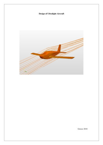
104MICHELINAIRCRAFT TIRECARE AND SERVICE MANUALCHAPTER 1 - AIRCRAFT TIRE DESCRIPTION/CONSTRUCTION4. Components Unique to MICHELIN Radial Aircraft Tires(All components shown may not be in all tires, due to design criteria.)SidewallTreadProtector PlyUndertreadBelt PliesCasing PliesChafer RubberLinerBeadCasing PlyTurn-upsFigure 102. Radial Aircraft Tire4.1.Protector Ply4.1.1. Single layer of steel or nylon fabric positioned underneath the tread.4.1.2. The protector ply provides cut resistance protection to the underlying belt plies and casing plies.4.1.3. Typically it is only found in retreadable tires, but may not be found in all of them.4.2.Belt Plies4.2.1. Belt plies are nylon or special fabric cords that are laid on top of the casing plies.4.2.2. Belt plies restrain the outer diameter of the tire, providing a tread surface with greater resistanceto squirm and wear as well as providing a more uniform pressure distribution in the footprint forimproved landing performance.4.3.Casing Ply4.3.1. In radial constructed tires, each nylon casing ply is laid at an angle approximately 90 to thecenterline or direction of rotation of the tire.NOTE: Radial constructed tires of the same size have a fewer number of casing plies than tires ofa bias construction because the radial tire uses the casing cords more efficiently.4.4.Bead4.4.1.4.4.2.4.5.Radial tires are constructed with 2 bead wire bundles (1 per side).Beads are fabricated from high strength steel wires layered together to form a bundle.Chafer Rubber4.5.1. Protective rubber laid over the outer casing plies in the bead area of the tire.4.5.2. Its purpose is to protect the casing plies from damage when mounting or dismounting and toreduce the effects of wear and chafing (light abrasion) between the wheel and the tire bead.MAT-CSM 32-45-01 Revision E32-45-01Description/Construction: Page 104 of 110Revision: 1 January 2016
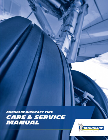
105MICHELINAIRCRAFT TIRECARE AND SERVICE MANUALCHAPTER 1 - AIRCRAFT TIRE DESCRIPTION/CONSTRUCTION4.6.Near Zero Growth (NZG)4.6.1. NZG technology is a development by Michelin for radial tires. This technology uses a newlydeveloped ultra-high tensile composite cord with less elongation than nylon cords.4.6.2. Tires constructed with NZG cord may use fewer plies to achieve the same tire strength andcapability. As such, NZG tires are lighter in weight and grow less than nylon constructed tires.The technology results in better resistance to foreign object damage (FOD) and landingperformance, in addition to the lighter weight.4.6.3. The use of NZG technology is not currently identified in the sidewall marking.5. Components Unique to MICHELIN Bias Aircraft Tires(All components shown may not be in all tires, due to design criteria.)SidewallTreadTread Reinforcing PlyUndertreadCasing PlyTurn-upsCasing PliesLinerChafer StripsBeadsFigure 103. Bias Aircraft Tire5.1.Tread Dimples (very limited applications):5.1.1. Half-sphere depressions molded in the tread rubber, in place of grooves, to act as a wear indicator.5.1.2. This tread design is limited to high flotation tires that are intended for landing on grass orunimproved runways.5.2.Fabric Tread (very limited applications)5.2.1. Fabric tread is a unique development for application on high speed military aircraft.5.2.2. Multiple plies of nylon cords are layered throughout the tread rubber.5.3.Spiral Wrap (very limited applications)5.3.1. Spiral Wrap is a technique used with retreaded tires.5.3.2. Individual textile cords are laid within the replacement tread rubber as it is applied to thetire casing.5.3.3. Due to their circumferential orientation, the textile cords provide added resistance to the cuttingand tearing action associated with chevron cutting.5.3.4. Cords can be visible during wear on the tread.MAT-CSM 32-45-01 Revision E32-45-01Description/Construction: Page 105 of 110Revision: 1 January 2016
106MICHELINAIRCRAFT TIRECARE AND SERVICE MANUALCHAPTER 1 - AIRCRAFT TIRE DESCRIPTION/CONSTRUCTIONFigure 104. Spiral Wrap5.4.Tread Reinforcing Ply5.4.1. Single or multiple layers of a special nylon fabric positioned underneath the tread.5.4.2.These plies help to strengthen and stabilize the crown area by reducing tread distortion underload and increasing high speed stability. They also offer resistance of the tread to puncture andcutting which helps protect the casing body.5.4.3.It is typically only found in retreadable tires, but may not be found in all of them.5.5.Casing Ply5.5.1. In bias constructed tires, nylon casing plies are laid at angles between 30 and 60 to thecenterline, or direction of rotation of the tire. Succeeding plies are laid with cord angles oppositeto each other to provide balanced casing strength.5.5.2. In some bias designs, supplemental plies are used to reinforce the casing in the tread area ofthe tire.5.6.Bead5.6.1.5.6.2.5.7.They are constructed from high-strength steel wires layered together to form a bundle.Bias tires are constructed with 2 to 8 bead bundles (1 to 4 per side), depending on the size anddesign application.Chafer Strips5.7.1. Strips of protective fabric or rubber laid over the outer casing plies in the bead area of the tire.5.7.2. Their purpose is to protect the casing plies from damage when mounting or dismounting and toreduce the effects of wear and chafing (light abrasion) between the wheel and the tire bead.MAT-CSM 32-45-01 Revision E32-45-01Description/Construction: Page 106 of 110Revision: 1 January 2016
CHAPTER 1 - AIRCRAFT TIRE DESCRIPTION/CONSTRUCTION5.8.New Bias Technology (NBT)NBT technology is a development unique to some MICHELIN Bias constructions. It consists of a casingcrown reinforcement placed on the inside of the tire located under the tread. This provides strengthand a more uniform pressure distribution in the footprint slowing the rate of wear and improvinglanding performance.NBT Casing CrownReinforcementFigure 105. NBT Bias Technology6. Sidewall Venting6.1.Aircraft tires have traditionally been designed to permit any air or nitrogen trapped in the internal cordbody, or that diffuses through the innerliner or tube, to escape through designed sidewall vents.6.2.Vent holes exist on both sides of the tire.6.3.Not all tires require vent holes due to materials, design and fabrication. This is particularlytrue for some physically smaller radial tires used in the General Aviation and high performanceMilitary applications.6.4.Tires requiring vent holes have them placed in the lower sidewall. The location of each vent hole isindicated by a colored paint dot when required. Refer to Figure 106.6.4.1. A Green color is used for tubeless tires.6.4.2. A White color is used for tube-type tires.6.4.3. Paint dots are applied to new tires. It is not required that they be refreshed on retreaded tires.MAT-CSM 32-45-01 Revision E32-45-01Description/Construction: Page 107 of 110Revision: 1 January 2016107MICHELINAIRCRAFT TIRECARE AND SERVICE MANUAL
108MICHELINAIRCRAFT TIRECARE AND SERVICE MANUALCHAPTER 1 - AIRCRAFT TIRE DESCRIPTION/CONSTRUCTIONSidewall VentsFigure 106. Lower Sidewall VentsNOTE: It is normal to see bubbles at the tire vent holes, just above the wheel flange, any timewhile the tire is inflated. Refer to Figure 107.NOTE: Do not identify a tire as leaking solely on the rate of bubbles from the vent holes.A leaking tire/wheel assembly should be determined by the pressure loss, as measuredwith a calibrated gauge, over a period of time.Bubbles FromSidewall VentsFigure 107. Appearance of Bubbles From Tire VentsMAT-CSM 32-45-01 Revision E32-45-01Description/Construction: Page 108 of 110Revision: 1 January 2016
109MICHELINAIRCRAFT TIRECARE AND SERVICE MANUALCHAPTER 1 - AIRCRAFT TIRE DESCRIPTION/CONSTRUCTION7. Chine Tires7.1.The “chine” tire is a nose wheel tire designed to deflect water and slush to the side and away from theintakes on aft-fuselage mounted jet engines.7.2.Chine tires have a protrusion on the upper sidewall which deflects the spray pattern of water or slushdisplaced by the tire’s contact with the runway.7.3.A tire can have a single chine for dual nose wheel tire configurations or double chine for single nosewheel tire configurations. Refer to Figure 108.7.4.The chine tire is used on some commercial, regional and private jets. It is retreadable when specified.Single ChineDual ChineFigure 108. Chine Nose TireMAT-CSM 32-45-01 Revision E32-45-01Description/Construction: Page 109 of 110Revision: 1 January 2016
110MICHELINAIRCRAFT TIRECARE AND SERVICE MANUALCHAPTER 1 - AIRCRAFT TIRE DESCRIPTION/CONSTRUCTIONThis Page IntentionallyLeft BlankMAT-CSM 32-45-01 Revision E32-45-01Description/Construction: Page 110 of 110Revision: 1 January 2016
MICHELINAIRCRAFT TIRECARE AND SERVICE MANUALCHAPTER 2 - AIRCRAFT TIRE TERMINOLOGY AND TIRE MARKINGS (BRANDING)1.1.This section provides basic information related to tire terminology used to describe and understandtire capabilities.1.2.A “New Tire” is a tire that has been stretched to its dimensions by inflating to the specified pressureand that has not been placed in service on an aircraft.1.3.A “Grown” tire has been stretched to its maximum dimensions during its service life, as a result ofinflation pressure, heat, and rotational forces.1.4.“B” or “H” prefix in the size designation indicates a rim width to section width ratio.1.5.Maximum Outside Diameter is maximum diameter of a new inflated tire measured on the center ofthe tread.1.5.1. Do Nominal overall diameter expressed in inches or millimeters.1.6.Section Width is the overall width at the widest point of a new inflated tire. The section width dimensiondoes not include the chine for tires with chine.1.6.1. W Nominal section width expressed in inches or millimeters.1.7.The Construction code is placed between the section width and the rim diameter.1.7.1. “–“ for bias tires.1.7.2. “R” for radial tires.1.8.Rim Diameter is the specified rim diameter.1.8.1. D Rim diameter expressed in inches or millimeters.1.9.Static Loaded Radius is the distance between the center of the wheel axle and the flat surface, onwhich the tire is loaded, when supporting its rated load while inflated to its rated pressure(at ambient temperature).1.10. Tire Deflection is the difference between half the outside diameter and the static loaded radius.2. Tire Sizes2.1.Tires are described by a combination of their physical dimensions. Depending on their intendedapplication the dimensions used to describe the tire are different.2.2.Tire size dimensions are standardized for a tire mounted on the proper rim, inflated to rated pressure atambient temperature.2.3.Dimensional tolerances are set by the Tire and Rim Association (T&RA) and/or the European Tyre andRim Technical Organization (ETRTO) and may also be found in each organization’s year book.2.3.1. Bias tire dimensions are for a “New” tire that has been inflated to the specified pressure for12 hours minimum.2.3.2. Radial tire dimensions are for a “Grown” tire that has been rolled the equivalent of50 TSO-C62 takeoff cycles.2.4.TYPE III tires size designation: High flotation, low pressure. Maximum speed usually 160 mph or less.2.4.1. Tire Size designation is shown as W – D. (Nominal section width - Rim diameter)2.4.2. Examples: 5.00 – 5 8.50 – 10MAT-CSM 32-45-01 Revision E32-45-01Marking and Terminology: Page 201 of 214Revision: 1 January 20162011. Tire Terminology
MICHELINAIRCRAFT TIRECARE AND SERVICE MANUALCHAPTER 2 - AIRCRAFT TIRE TERMINOLOGY AND TIRE MARKINGS (BRANDING)TYPE VII tire size designation: High pressure, narrow section widths for high speed aircraft.2.5.1. Tire Size designation is shown as Do x W. (Overall Diameter x Nominal section width)2.5.2. Examples: 26 x 6.6 49 x 172.6.THREE PART Nomenclature: Used for all recent and newly designed tire sizes, all applications.2.6.1. Size designation: Do x W – D. (Overall Diameter x Nominal section width – Rim diameter)2.6.2. Bias Size Examples: 27 x 7.75 – 15 H44.5 x 16.5 – 21 (“H” type)2022.5.2.6.3.2.6.4.2.7.Size designation: Do x W R D.Radial Size Examples: 50 x 20.0 R 22 1400 x 530 R 23 (metric) H41 x 16.0 R 20 (“H” type)TUBES are sized and identified the same way as the tire size for which they are to be used.2.7.1. Examples: 6.00 – 6 15x6.0 – 63. Tire Markings (Branding)3.1.This section provides information on typical tire markings for both new and retread tires along withcommon terminology.3.2.Markings are molded into the rubber surface during manufacturing and remain there throughoutthe tire’s life.3.2.1. Markings provide information that describes the tire, its design capabilities, manufacturinginformation, and certification.3.2.2. Tire Markings will vary depending on the market application, whether bias or radial, andreflect the requirements in place at the time of certification.3.3.New Tire Markings and Descriptions:3.3.1. New Tire Markings appear on both sidewalls (Refer to Figures 201 - 205) and are to remain on atleast one sidewall of the tire throughout its service life.3.3.2. Ply Rating (PR) for a given
4. Pre-Assembly Checklist for the Tire/Wheel Assembly (Hub) 404 5. Mounting (Assembly) - Tubeless Tires 407 6. Mounting (Assembly) - Tube-Type Tires 409 7. Infl ation of a Tire/Wheel Assembly to Operational Pressure 411 MAT-CSM 32-45-01 Revision E 32-45-01 Table of Contents: Page 1 of 2 Revision: 1 January 2016 MICHELIN AIRCRAFT TIRE