Transcription
LECTURE NOTESONDESIGN FOR MANUFACTURING AND ASSEMBLYCOURSE CODE A70339IV B.TECH. I SEM JNTUHPrepared ByMr. A. Venu PrasadAssistant ProfessorMECHANICAL ENGINEERINGINSTITUTE OF AERONAUTICAL ENGINEERING(AUTON0MOUS)DUNDIGAL, HYDERABAD - 500 0431
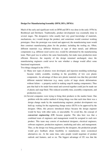
UNIT-IINTRODUCTIONWhat is ―DFMA‖? The concept of DFM (Design for Manufacture) is not new, it dates back as early as1788 when LeBlanc, a Frenchman, devised the concept of inter-changeable parts in the manufacture ofmuskets which previously were individually handmade. DFM is the practice of designing productskeeping manufacturing in mind. ―Design for manufacture‖ means the design for ease of manufacture forthe collection of parts that will form the product after assembly. Similarly DFA is called Design forAssembly. DFA is the practice of designing product with assembly in mind. ―Design for assembly‖means the design of the product for ease of assembly. So design for Manufacture and assembly is thecombination of DFM and DFA as shown in Figure 1.1Figure 1.1: Definition of Design for Manufacture & Assembly (DFMA)DFMA is used for three main activities:1. As the basis for concurrent engineering studies to provide guidance to the design team insimplifying the product structure to reduce manufacturing and assembly costs, and to quantify theimprovements.2. As a benchmarking tool to study competitors‘ products and quantify manufacturing and assemblydifficulties.3. As a should-cost tool to help control costs and to help negotiate suppliers contracts.2
Product cost Commitment during phases of the design process―Decisions made in the design process cost very little in terms of the overall product cost but have amajor effect on the cost of the product.‖―You cannot compensate in manufacturing for defects introduced in the design phase‖―The design process should be conducted so as to develop quality, cost – competitive products in theshortest time possible‖TYPES OF DESIGNSOriginal design Adaptive design RedesignVariant designSelection design:::Industrial design:Innovationeg: MicroprocessorNovel applicationeg: inkjet printing conceptfor rapid prototypingWithout any change in concept of the original designchanging some of the design parametersSelecting the components with the needed performance,quality and cost from the catalogs of potential vendorsAppeal of product to human senses.3
Step in Design Process:Steps for applying DFMA during product design:The following steps are followed when DFMA used in the design process. DFA analysis lading to simplification of the product structure Early cost estimation of parts for both original design and modified design Selecting best material and process to be used After final selection of material and process carry out a thorough analysis of DFMFigure 1.2 depicts the flow diagram of various steps undertaken in a DFMA study using DFMAsoftware. FigureFigure 1.2: Common steps taken in a DFMA studyDesign Concept Design for Assembly (DFA) Selection of materials and processes and early DFM costestimates Best design concept Design for Manufacture (DFM) Production Prototype Suggestions formore economic materials and processes Suggestions for simplification of product structure.4
Advantages of applying DFMA during product DesignToday products are– Tending to becoming more complex– Made/required in increasingly large number– Intended to satisfy a wide variation in user population– Required to compete aggressively with similar products– Required to consistently high qualityThrough DFMA it is possible to produce competitively priced, high performance product at a minimalcost. The advantages of applying DFMA during product design are as follows: DFMA not only reduces the manufacturing cost of the product but it helps to reduce the timeto market and quality of the product.DFMA provides a systematic procedure for analyzing a proposed design from the point ofview of assembly and manufacture.Any reduction in the number of parts reduces the cost as well as the inventory.DFMA tools encouraged the dialogue between the designer and manufacturing engineerduring the early stages of design.General design rules for manufacturing ability:(1)(2)(3)(4)(5)(6)Product life, volumePermissible tooling expenditure levelsPossible part shape categories and complexity levelsService or environment requirementsAppearance factorsAccuracy factorsMaterials:Relation of Materials Selection to Design:An incorrectly chosen material can lead not only to failure of the part but also to excessive life-cyclecost. Selecting the best material for a part involves more than choosing both a material that has theproperties to provide the necessary performance in service and the processing methods used to create thefinished part (Fig. 1.3). A poorly chosen material can add to manufacturing cost. Properties of thematerial can be enhanced or diminished by processing, and that may affect the service performance ofthe part.Faced with the large number of combinations of materials and processes from which to choose, thematerials selection task can only be done effectively by applying simplification and systemization. Asdesign proceeds from concept design, to configuration and parametric design (embodiment design), and5
to detail design, the material and process selection becomes more detailed. Figure 1.2 compares thedesign methods and tools used at each design stage with materials and processes selection.At the concept level of design, essentially all materials and processes are considered in broad detail.The materials selection methodology and charts developed by Ashby 2 are highly appropriate at thisstage.The task is to determine whether each design concept will be made from metal, plastics, ceramic,composite, or wood, and to narrow it to a group of materials within that material family. The requiredprecision of property data is rather low.Note that if an innovative choice of material is to be made it must be done at the conceptual designphase because later in the design process too many decisions have been made to allow for a radicalchange. The emphasis at the embodiment phase of design is on determining the shape and size of a partusing engineering analysis.The designer will have decided on a class of materials and processes, such as a range of aluminumalloys, wrought and cast. The material properties must be known to a greater level of precision. At theparametric design step the alternatives will have narrowed to a single material and only a fewmanufacturing processes.Here the emphasis will be on deciding on critical tolerances, optimizing for robust design and selectingthe best manufacturing process using quality engineering and cost modeling methodologies. Dependingon the importance of the part, materials properties may need to be known to a high level of precision.This may require the development of a detailed database based on an extensive materials testingprogram. Thus, material and process selection is a progressive process of narrowing from a largeuniverse of possibilities to a specific material and process (Fig. 1.4).6
Figure 1.4 Schematic of the design process, with design tools shown on the left and materials andprocess selection on the right. Shows the refining method used to arrive at the best combination ofmaterial and manufacturing process.General Criteria for SelectionMaterials are selected on the basis of four general criteria: Performance characteristics (properties) Processing (manufacturing) characteristics Environmental profile Business considerationsSelection on the basis of performance characteristics is the process of matching values of theproperties of the material with the requirements and constraints imposed by the design.Selection on the basis of processing characteristics means finding the process that will form thematerial into the required shape with a minimum of defects at the least cost. Selection on the basis of anenvironmental profile is focused on predicting the impact of the material throughout its life cycle on theenvironment. As discussed in Sec. 8.9, environmental considerations are growing in importance because7
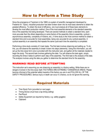
of the dual pressures of greater consumer awareness and governmental regulation.The chief business consideration that affects materials selection is the cost of the part that is madefrom the material. This considers both the purchase cost of the material and the cost to process it into apart. A more exact basis for selection is life-cycle cost, which includes the cost of replacing failed partsand the cost of disposing of the material at the end of its useful life.Selection charts:Each manufacturing process can be characterized by a set of attributes similar to what have beenillustrated for materials in the earlier lectures. Process-Material matrix: Figure 1.8 represents a typicalprocess-material matrix indicating the general compatibility between manufacturing process andengineering material. The processes are also broadly classified as shaping, joining and finishing. The dotindicates that the pair of the material and the process is compatible. For example, sand casting or diecasting process cannot be used for processing of composite materials. Thus, an initial screening ofprocesses for a given material can be easily performed based Figure 1.8.Figure.1.7. Process–Material matrix with the dot indicating a compatibility between the material and thecorresponding manufacturing process [2]8
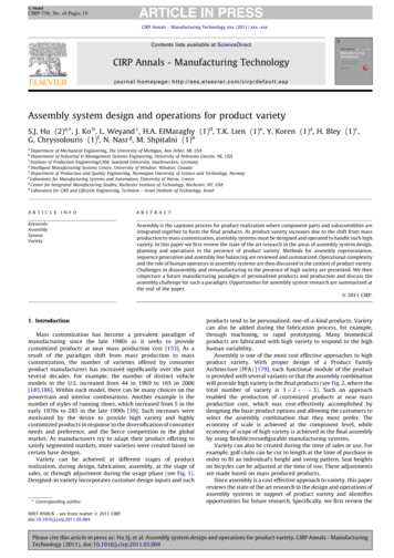
Process-Shape matrix: Figure 3.8.3 presents a broad classification of different shapes that arecommonly encountered in product design. Various manufacturing processes are capable of making theseshapes.For example, a typical turning operation creates axisymmetric shapes while extrusion, drawing androlling make prismatic shapes – both circular and non-circular.The sheet forming processes can make flat or dished shapes. Certain manufacturing processes can makethree-dimensional shapes.Figure 3.8.4 depicts a typical Process vis-à-vis Shape compatibility chart indicating the ability ofvarious manufacturing processes in producing different shapes. Often a single process is unable to givethe final shape of a product and it is necessary to combine two or more processes.Figure 1.8 General classification of shapes [2]9
Figure 1.9 Process–Shape matrix with the dot indicating a compatibility between the shape and thecorresponding manufacturing process [2]Process-Mass bar-chart: Figure 1.10 shows the typical mass-range of components that each process canmake. Large components can be built up by joining smaller ones. For this reason the ranges associatedwith joining are shown in the lower part of Figure 1.10. It can be noted IIT BOMBAY that sand castingprocess, for example, is capable of producing large component while die casting or investment castingprocesses can make relatively smaller sized parts.10
Figure 1.10 Process–Mass bar chart indicating compatibility between the requisite mass of a part and thecorresponding manufacturing process [2]Process-Section thickness bar-chart: The selection of a manufacturing process also depends on thesection thickness of the part to be made. Each process has its limit over the range of the sectionthickness, which it can produce. For example, surface tension and the typical nature of heat flow limit theminimum section and slenderness of gravity-die cast shapes. Bulk deformation processes cover a widerrange of section thickness.Limits on forging pressures also set a lower limit on the section thickness and slenderness that can beforged. Powder forming methods are more limited in the section thicknesses they can create, but they canbe used for ceramics and very hard metals that cannot be shaped in other ways. Special techniques suchas electro-forming, plasma spraying allow manufacturing of slender shapes. Figure 1.11 depicts thetypical manufacturing processes and the range of section thickness that each process can manufacture.11
Figure 1.11 Process–Section thickness bar chart indicating compatibility between the manufacturing processand the range of section thickness that each process can produce [2]Process – Dimensional Tolerance bar-charts: Tolerance and surface roughness that a specificmanufacturing process can provide is an important characteristic. Manufacturing processes vary in thelevels of tolerance and roughness they can achieve economically. Figures 1.12 and 1.13 shows theprocess vis-à-vis range of achievable dimensional tolerance and the process vis-à-vis range of minimumachievable surface roughness bar charts, respectively.For example, die casting process with the permanent metallic dies can give better surface finishcompared to the same achievable in sand casting. Machining is capable of delivering high dimensionalaccuracy and surface finish when the process parameters are controlled properly. Grinding can beadopted to achieve very high tolerance while such precision and finishing operations are generallyexpensive.12
Figure 1.12 Process – Tolerance Limit bar chart indicating compatibility between the manufacturingprocess and tolerance limit [2]13
Figure 1.13 Process – Surface roughness Limit bar chart indicating compatibility between themanufacturing process and minimum surface roughness limit [2]How to use the process selection charts?The charts described above provide a quick overview and comparison of the capabilities of variousmanufacturing processes. However, these charts must be used sufficiently carefully for a given shape,material, dimension, requisite tolerances and surface roughness considering the both the capabilities andlimitations of various processes. Often, the major cost associated with a given part lies from the wrongchoice of manufacturing process (es). Following are some generic steps which are often followed in theselection of manufacturing process such as: keep things standard keep things simple design the parts so that they are easy to assemble do not specify more performance than is needed.14
UNIT – IIDESIGN FOR MANUFACTURING, CASTINGMachining Process:Overview of various Machining Processes:Turning:Turning is the most important machining process and can produce a wide variety of parts.Primarily, turning is used to produce parts round in shape by a single point cutting tool on lathemachines. The cutting tool is fed either linearly in the direction parallel or perpendicular to the axis ofrotation of the work piece, or along a specified path to produce complex rotational shapes.The primary motion of cutting in turning is the rotation of the work piece, and the secondary motion ofcutting is the feed motion. Figure 2.1 depicts a typical turning operation in lathe machine. Different typesof lathe machines are available today from general purpose to specific job oriented special purposemachines. In general, turning refers to a class of processes carried out on a lathe machine. A brief outlineof some the sub-class of turning processes are presented belowFigure 2.1 Classification of Machining Processes15
Figure 2.3 Schematic depiction of turning operationStraight turning is used to reduce the diameter of a part to a desired dimension (Figure 2.3 a). Theresulting machined surface is cylindrical.Contour turning and Taper turning (Figure 2.3b) are performed by employing a complex feed motionusing special attachments to a single point turning tool thus creating a contoured shape on the workpiece.Facing (Figure 2.3c) is done to create a smooth, flat face perpendicular to the axis of a cylindrical part inan accurate manner. The tool is fed radially or axially to create a flat machined surface.Thread cutting (Figure 2.3d) is possible in lathe machine by advancing the cutting tool at a feed exactlyequal to the thread pitch.The single-point cutting tool cuts in a helical band, which is actually a thread. The tool point must beground so that it has the same profile as the thread to be cut. Thread can be both external and internaltypes. In form turning (Figure 2.3e), the shape of the cutting tool is imparted to the work piece byplunging the tool into the work piece.In form turning, the cutting tool can be very complex and expensive but the feed will remain linear andwill not require special machine tools or devices. Boring (Figure 2.3f) is similar to straightturning operation but differs in the fact that it can produce internal surface of revolution, which is oftenconsidered to be difficult due to overhanging condition of the tool.16
Figure 2.3 Different types of Turning OperationsStraight turning is used to reduce the diameter of a part to a desired dimension (Figure 2.3a). Theresulting machined surface is cylindrical. Contour turning and Taper turning (Figure 2.3b) areperformed by employing a complex.Milling:Milling is a process of producing flat and complex shapes with the use of multi-point (or multi-tooth)cutting tool. The axis of rotation of the cutting tool is perpendicular to the direction of feed, eitherparallel or perpendicular to the machined surface.Milling is usually an interrupted cutting operation since the teeth of the milling cutter enter and exitthe work piece during each revolution. This interrupted cutting action subjects the teeth to a cycle ofimpact force and thermal shock on every rotation. The tool material and cutter geometry must bedesigned to withstand these conditions. Figure 2.5 depicts two basic types of milling operations: downmilling, when the cutter rotation is in the same direction as the motion of the work piece being fed, andup milling, in which the work piece is moving towards the cutter, opposing the cutter direction ofrotation.In down milling, the cutting force is directed on to the work table, which allows thinner parts to bemachined without susceptibility to breakage. Better surface finish is obtained in down milling but thestress load on the teeth is abrupt, which may damage the cutter. Backlash eliminator has to be used in thisoperation. In up milling, the cutting action tends to lift the work piece and hence, Proper fixture isrequired in this operation.17
Figure 2.4 Schematic depiction of down milling (a) and up milling (b) operationsDepending on the orientation and geometry of the milling tool, several varieties of milling operationsare possible. In peripheral milling (Figure 2.5a), also referred to as plain milling, the axis of the cutter isparallel to the surface being machined, and the operation is performed by the cutting edges on the outsideperiphery of the tool.The primary motion is the rotation of the tool. The feed is imparted to the work piece. In face milling(Figure 2.5b), the tool is perpendicular to the machined surface. The tool axis is vertical, and machiningis performed by the teeth on both the end and the periphery of the face-milling tool. Also, up and downtypes of milling are available, depending on directions of the toolrotation and feed. End milling is used to produce pockets, key holes by using a tool referred to as the endmill, has a diameter less than the work piece width. In form milling (Figure 2.5c), the cutting edges of theperipheral tool (also referred to as form cutter) have a special profile that is imparted to the work piece.Tools with various profiles are also available to cut different two-dimensional surfaces. One importantapplication of form milling is in gear manufacturing.Surface contouring (Figure 2.5d), is an operation performed by computer controlled milling machines inwhich a ball-end mill is fed back and forth across the work piece along a curvilinear path at closeintervals to produce complex three-dimensional surfaces.18
Figure 2.5 Different types of milling operationsDrilling:Drilling is a process of producing round holes in a solid material or enlarging existing holes with theuse of multi-point cutting tools called drills or drill bits. Various cutting tools are available for drilling,but the most common is the twist drill. A variety of drilling processes (Figure 2.6) are available to servedifferent purposes. Drilling is used to drill a round blind or through hole in a solid material. If the hole islarger than 30 mm, a smaller pilot hole is drilled before core drilling the final one. For holes larger than 50 mm, three-step drilling is recommended. Core drilling is used to increase the diameter of an existinghole. Step drilling is used to drill a stepped (multi-diameter) hole in a solid material. Counter boringprovides a stepped hole again but with flat and perpendicular relative to hole axis face. The hole is usedto seat internal hexagonal bolt heads. Countersinking is similar to counter boring, except that the step isconical for flat head screws.19
Reaming operation is usually meant to slightly increase the size and to provide a better tolerance andsurface finish of an initially drilled hole. The tool is called reamer. Center drilling is used to drill astarting hole to precisely define the location for subsequent drilling operation.The tool is called center drill that has a thick shaft and very short flutes. Gun drilling is a specificoperation to drill holes with very large length-to-diameter ratio up to 300. There are severalmodifications of this operation but in all cases cutting fluid is delivered directly to the cutting zoneinternally through the drill to cool and lubricate the cutting edges, and to remove the chips.Figure 2.6 Different Types of Drilling OperationsPlaning , Shaping and Broaching:Planing and shaping (Figure 2.7) are similar operations, which differ only in the kinematics of theprocess.Planing is a machining operation in which the primary cutting motion is performed by the work pieceand feed motion is imparted to the cutting tool. In shaping, the primary motion is performed by the tool,and feed by the work piece.20
Figure 2.7 Kinematics of shaping and planningBroaching is a machining operation that involves the linear movement of a muti-point cutting tool(referred to as broach) relative to the work piece in the direction of the tool axis. The shape of themachined surface is determined by the contour of the final cutting edges on the broach.Broaching is a highly productive method of machining with advantages like good surface finish, closetolerances, and the variety of possible machined surface shapes some of them can only be producedby broaching. Owing to the complicated geometry of the broach, the tooling is expensive. The broachingtools cannot be reground and have to be replaced when wear becomes excessive. Broaching is a typicalmass production operation.Figure 2.8 Schematic of broaching operation [1]Grinding:Grinding (Figure 2.9) is the most popular form of abrasive machining. It involves an abrasive toolsconsisting of grain of hard materials which are forced to rub against the work piece removing a very21
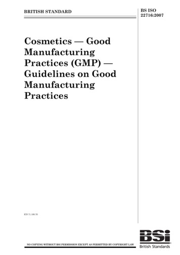
small amount of material. Due to the random orientation of grains and some uncontrollable cuttingcondition, the selection of proper parameters often becomes difficult. Grinding can be performed toproduce flat as well as cylindrical (both external and internal) surface efficiently. Grinding is appliedwhen the material is too hard to be machined economically or when tolerances required are very tight.Grinding can produce flatness tolerances of less than 0.0025 mm ( 0.0001 in) on a 127 x 127 mm (5x 5 in) steel surface if the surface is adequately supported. In recent times, enormous amount of researchwork has made grinding process very economical and efficient for removing a large thickness of materialalso. The major advantages of grinding process include dimensional accuracy, good surface finish, goodform and locational accuracy applicable to both hardened and unhardened material.Figure 2.9 Schematic of grinding operationAbrasive Finishing:As the name indicates, these groups of operations are used to achieve superior surface finish up tomirror-like finishing and very close dimensional precision. The finishing operations are assigned as thelast operations in typical single part production cycle usually after the conventional or abrasivemachining operations. Honing, Lapping, Super finishing, Polishing process comes under this group.Figure 2.10 depicts a comparison of surface roughness values for different processes.22
Figure 2.10 Comparison of surface roughnessNon Traditional Machining Processes:To distinguish the non-traditional machining (NTM) processes from the traditional or conventional ones,it is necessary to understand the differences and the similar characteristics between conventionalmachining processes and NTM processes.The conventional processes generally involve a wedge shaped cutting tool to remove material in theform of chip by causing plastic deformation and shear failure. The cutting tool has to be harder than thework piece at room temperature as well as under machining conditions. However, the non-traditionalprocesses commonly embody by the following characteristics:Material removal may occur with or without the conventional chip formation, A physical cutting toolmay not always be present [e.g. a typical laser beam is used for machining in laser jet machining process.The tool material needs not be harder than the work piece material. Majority of the non-traditionalmachining processes do not necessarily use mechanical energy and rather different other forms of energyfor material removal.Some commonly used non-traditional machining processes are described below.:Abrasive Jet Machining:Abrasive jet machining (Figure 2.11) process involves impinging of fine abrasive particles on the workmaterial at a very high velocity causing small fracture on the workpiece surface on impact. A gas streamcarries both the abrasive particles and the fractured particles away. The jet velocity is in the range of 15023
300 m/s and the applied pressure can range from two to ten times of atmospheric pressure. Abrasive JetMachining (AJM) is used for deburring, etching, and cleaning of hard and brittle metals, alloys, andnonmetallic materials.Figure 2.11 Schematic depiction of Abrasive Jet MachiningUltrasonic Machining:In ultrasonic machining (Figure 2.12), a tool of desired shape vibrates at an ultrasonic frequency (19 25 kHz) with an amplitude of around 15 – 50 μm over the work piece. The tool is pressed downwardwith a feed force and the machining zone is flooded with hard abrasive particles generally in the form ofwater based slurry. As the tool vibrates at ultrasonic frequency, the abrasive particle removes material byindentation. This process can be used for very accurate machining of hard and brittle metallic alloys,semiconductors, glass, ceramics, carbides, wire drawing and punching dies, etc.Figure 2.12 Schematic depiction of Ultrasonic Machining24
Water Jet and Abrasive Water Jet Machining:Water Jet Machining uses a fine, high-pressure, high velocity (faster than the speed of sound) stream ofwater directed at the work surface to cause material removal. The cutting ability of water jet machiningcan be improved drastically by adding hard and sharp abrasive particles into the water jet and is termedas Abrasive Water Jet machining. This jet is sprayed over the work surface with very high pressurecausing removal of material by the indentation action. Typical application of these processes includespaint removal, cleaning and cutting of sheets especially of softer materials, cutting of frozen meat,dismantling of nuclear plant parts, etc.Electro Chemical Machining:Electro chemical machining (Figure 2.13) can be thought of a controlled anodic dissolution at atomiclevel of an electrically conductive work piece due to the flow of high current at relatively low potentialdifference. The machining process is attained by a shaped tool. Both the work piece and the tool aresubmerged into a suitable electrolyte which is often the water based neutral salt solution. In principle, itcan be considered to be opposite of electrochemical coating process. As the tool does not contact thework piece, there is no need to use expensive alloys to make the tool tougher or harder than the workpiece, which is a distinct advantage. There is less tool wear, and less heat and stresses are producedduring this process. High tooling costs and risk of corrosion due to electrolyte are some disadvantages ofthis process.Figure 2.13 Schematic outline of Electro Chemical MachiningElectro Discharge Machining:Electro Discharge Machining (EDM) (Figure 2.14) is an electro-thermal non-traditional machiningprocess, where electrical energy is used to generate electrical spark between the tool and the work piece.The material removal occurs primarily by vaporization of work piece material due to high thermal energyof the spark. Electro-discharge machining is mainly used to machine difficult-to-machine materials andhigh strength and temperature resistant alloys. Difficult geometries in small batches or even on job-shopbasis can be produced using this process. The only important point is that the work piece material has tobe electrically conductive. Some of the major advantages of this process are as follows:25
Complex shapes that are difficult to machine with conventional processes, can be done easily by electrodischarge machining process,Extremely hard material can be machined to close tolerances, Very small work pieces can be handledwith sufficient ease, and A good surface finish can be obtained. When the tool in electro dischargemachining process is replaced by a continuously moving small diameter electrically conducting wire, thesame is referred to as wire- electro discharge machining process that is widely used to cut a narrow kerfin the work piece.Figure 2.14 Schematic depiction of Electro discharge MachiningLaser and Electron Beam Machining :Laser beam machining (LBM) (Figure 2.15a) uses the light energy from a laser to remove material byvaporization and ablation whereas electron beam machining (EBM) uses a high-velocity stream ofelectrons focused on
means the design of the product for ease of assembly. So design for Manufacture and assembly is the combination of DFM and DFA as shown in Figure 1.1 Figure 1.1: Definition of Design for Manufacture & Assembly (DFMA) DFMA is used for three main activities: 1. As the basis for concurrent engineering studies t