Transcription
Assembly Design GuidelinesIssue XIX, Aug 2016A DEFINITIVE GUIDE TO DESIGN FOR MANUFACTURING SUCCESS2
Copyright Notice Geometric Limited. All rights reserved.No part of this document (whether in hardcopy or electronic form) may be reproduced, stored in a retrieval system,or transmitted, in any form or by any means, electronic, mechanical, photocopying, recording, or otherwise, to anythird party without the written permission of Geometric Limited. Geometric Limited reserves the right to change theinformation contained in this document without prior notice.The names or trademarks or registered trademarks used in this document are the sole property of the respectiveowners and are governed/ protected by the relevant trademark and copyright laws.This document is provided by Geometric Limited for informational purposes only, without representation or warrantyof any kind, and Geometric Limited shall not be liable for errors or omissions with respect to the document. Theinformation contained herein is provided on an “AS-IS” basis and to the maximum extent permitted by applicablelaw, Geometric Limited hereby disclaims all other warranties and conditions, either express, implied or statutory,including but not limited to, any (if any) implied warranties, duties or conditions of merchantability, of fitness for aparticular purpose, of accuracy or completeness of responses, of results, of workmanlike effort, of lack of viruses,and of lack of negligence, all with regard to the document.THERE IS NO WARRANTY OR CONDITION OF NON-INFRINGEMENT OF ANY INTELLECTUAL PROPERTY RIGHTS WITHREGARD TO THE DOCUMENT. IN NO EVENT WILL GEOMETRIC LIMITED BE LIABLE TO ANY OTHER PARTY FOR LOSTPROFITS, LOSS OF USE, LOSS OF DATA, OR ANY INCIDENTAL, CONSEQUENTIAL, DIRECT, INDIRECT, OR SPECIALDAMAGES WHETHER UNDER CONTRACT, TORT, WARRANTY, OR OTHERWISE, ARISING IN ANY WAY OUT OF THISDOCUMENT, WHETHER OR NOT SUCH PARTY HAD ADVANCE NOTICE OF THE POSSIBILITY OF SUCH DAMAGES.A DEFINITIVE GUIDE TO DESIGN FOR MANUFACTURING SUCCESS3
Welcome to another issue of the DFM Guidebook. This issue of DFM Guidebook will focuson design for assembly guidelines.This time we will not be talking about DFM. On the other hand we will cover some aspectsof DFA or Design for (ease of) Assembly. Consideration of assembly issues during earlydesign stage shortens product development time, minimizes development cost, andensures a smooth transition into production with minimal rework. If a product containsfewer parts it will take less time to assemble, thereby reducing assembly costs.With each part there is an opportunity for a defective part and an assembly error. As thenumber of parts increases, the probability of a perfect product goes down exponentially. Inaddition, if the parts are provided with features which make it easier to grasp, move, orientand insert them, this will also reduce assembly time and assembly costs. Additionally, thereare many assembly related issues which occur on the shop floor and can be avoided duringthe design stage.Read the guidebook to understand rules for: Hole Alignment, Hole to Slot Alignment, Slotparameters based on thread size, Interference Detection, Fastener Clearance, FastenerAccessibility, Fastener Engagement Length, Minimum Clearance between Components andCheck for Preferred Components.If you have any feedback or questions on DFM guidebook, please write to us atinfo@dfmpro.comHappy Reading .RegardsDFMPro Marketing.A DEFINITIVE GUIDE TO DESIGN FOR MANUFACTURING SUCCESS4
ContentsHole alignment . 6Hole and Slot pairs. 7Hole to Slot Alignment . 7Slot Parameters based on Hole Thread Size . 8Interference Detection . 9Fastener Guidelines . 10Fastener Accessibility . 10Fastener Clearance . 11Fastener Engagement . 12Recommended Thread Connection . 13Check Contact Material. 14Check Preferred Components . 15A DEFINITIVE GUIDE TO DESIGN FOR MANUFACTURING SUCCESS5
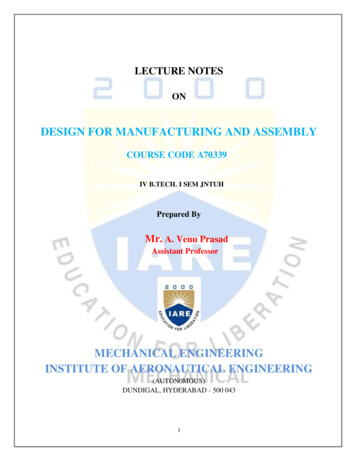
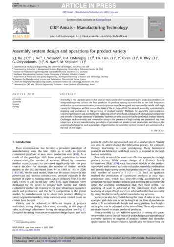
Hole alignmentHole alignment plays a major role in assembly design. Holes are used for insertion of fasteners, dowels,cables, etc.It is recommended that, holes in connecting parts should be collinear to avoid difficulties in assembly.Blocked holes and unused holes which lead to increase in manufacturing cost should be avoided.A DEFINITIVE GUIDE TO DESIGN FOR MANUFACTURING SUCCESS6
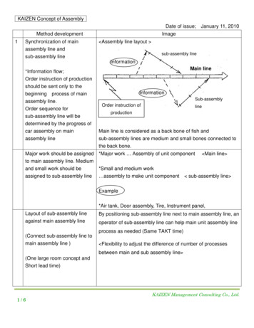
Hole and Slot pairsSlot holes are used in single-direction accurate joints. This is typically used where the alignmenttolerance along the length of the slot is not critical.Hole to Slot AlignmentCorrect hole to slot alignment id provided for proper position of the slot with respect to the threadedhole in the adjacent part. This should be measured by slot position center to the threaded hole axis.It is recommended that, hole should collinear and at the center of a slot. If the hole is not at the centerof the slot, then it may leads to misalignment in future adjustment.A DEFINITIVE GUIDE TO DESIGN FOR MANUFACTURING SUCCESS7
Slot Parameters based on Hole Thread SizeSlot parameters (Slot width and length) should be maintained as per the corresponding threaded holesizes. These slots will act as clearance holes.It is recommended that, for ease of manufacturing, slot parameters should be in standard sizes.A DEFINITIVE GUIDE TO DESIGN FOR MANUFACTURING SUCCESS8
Interference DetectionTo achieve desired functionality and ease of assembly interference between assembly componentsmust be avoided. Interference detection is most useful in complex assemblies, where it can be difficultto visually determine whether components interfere with each other.Failure to avid interference may result in rework and engineering changes.A DEFINITIVE GUIDE TO DESIGN FOR MANUFACTURING SUCCESS9
Fastener GuidelinesA fastener is a mechanical component which is used to join two or more parts/components together.Fasteners play a major role in assemblies.Fastener AccessibilityFasteners should be easily accessible for assembly and disassembly.It is necessary to ensure sufficient space around the fastener head for spanners, wrenches, bits for easeof fastening or extraction. Also, a designer should provide sufficient space axially for insertion andremoval of fastener into the holes.A DEFINITIVE GUIDE TO DESIGN FOR MANUFACTURING SUCCESS10
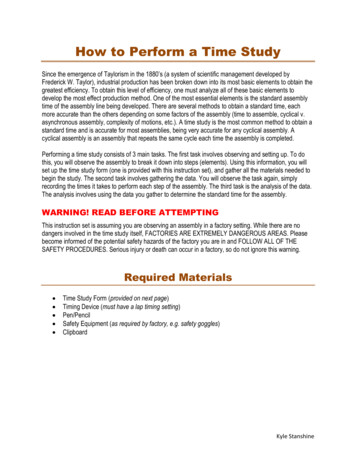
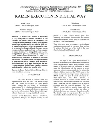
Fastener ClearanceFor the ease of insertion of fasteners there should be sufficient clearance between non-threaded partsand the fasteners (radial clearance).Also, it is advised to provide sufficient gap between bolt and bottom of the hole or the next component(axial clearance) to absorb excessive tightening load if any.A Axial Clearance , B Radial ClearanceA DEFINITIVE GUIDE TO DESIGN FOR MANUFACTURING SUCCESS11
Fastener EngagementThe axial distance through which the fully formed threads of both the nut and bolt are in contact iscalled the fastener (thread) engagement length.It is recommended that, engagement between the internal and external thread should be long enoughto provide adequate cross-sectional thread area. Insufficient thread engagement results in a tensilefailure of the bolt rather than thread stripping. To achieve the required strength, there should besufficient engagement between fastener and the component.A DEFINITIVE GUIDE TO DESIGN FOR MANUFACTURING SUCCESS12
Recommended Thread ConnectionThe threads on male (external) and female (internal) sides of a threaded connection should be ofcompatible types/forms. It is recommended to use only the compatible thread types/forms on maleand female sides of a threaded connection to avoid issues like improper connection, cracks, stressruptures etc. during functioning.Designer should select right threads (standard and size) in both male and female parts. For example, Ifthe male part thread is metric thread (M8 X 1.0) female part should have metric thread (M8 X 1.0).In some cases, even though thread standard and sizes are same but male thread is fine thread andfemale part thread may coarse thread, designer has to avoid such mismatches.A DEFINITIVE GUIDE TO DESIGN FOR MANUFACTURING SUCCESS13
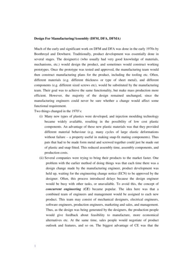
Check Contact MaterialCompatible contact material is one of the critical criteria in assembly design. Material propertiesdetermine, how the parts react to the structural or thermal loads applied. While selecting material,designer need to consider density, thermal conductivity, Specific heat, Coefficient of thermal expansionand so on.Metal oxidizes in presence of oxygen. Atmospheric effects and thermal cycling accelerates this process,when moisture is present. To avoid chemical reactions like oxidization or corrosion etc. contactmaterials should be compatible.SURFACE CONTACT ExamplesLOWERUPPER ELALUMINIUMCOPPERNOTE :YESCONTACT ACCEPTABLEY/NCCONTACT ACCEPTABLE BUT NOT DIRECT METAL CONTACTNONO DIRECT METAL CONTACTA DEFINITIVE GUIDE TO DESIGN FOR MANUFACTURING SUCCESS14
Check Preferred ComponentsIn most organizations, similar products with different versions or series are produced by way ofmodification or replacement of components. This is done with a purpose of making the productavailable with various features at different costs based on market demand.In such cases, it is important to ensure the presence of preferred and allowed components in the finalassembly based on the product or series. Goal is to exclude disallowed components from the finalassembly of a particular product version or series. Also, sometimes, materials assigned for disallowedcomponent are deemed obsolete by organizations. Hence, it needs to be ensured that suchcomponents are not be shipped with the final assembly.A DEFINITIVE GUIDE TO DESIGN FOR MANUFACTURING SUCCESS15
on design for assembly guidelines. This time we will not be talking about DFM. On the other hand we will cover some aspects of DFA or Design for (ease of) Assembly. Consideration of assembly issues during early design stage shortens