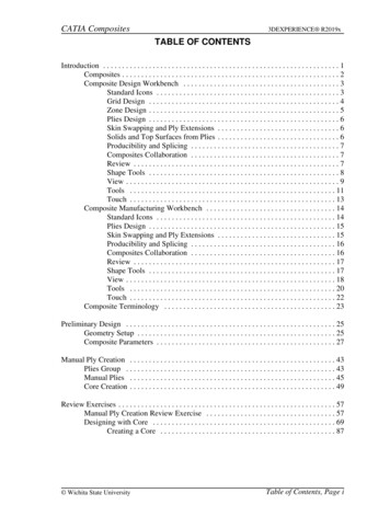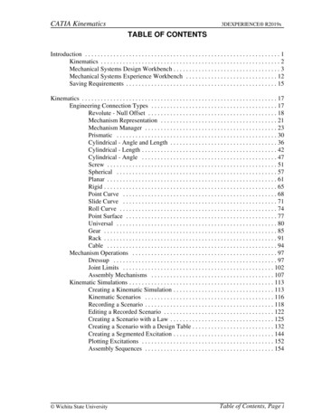
Transcription
CATIA Assembly Design3DEXPERIENCE R2019xTABLE OF CONTENTSIntroduction . . . . . . . . . . . . . . . . . . . . . . . . . . . . . . . . . . . . . . . . . . . . . . . . . . . . . . . . . . . . . . 1Assembly Design . . . . . . . . . . . . . . . . . . . . . . . . . . . . . . . . . . . . . . . . . . . . . . . . . . . . 2Assembly Design Workbench . . . . . . . . . . . . . . . . . . . . . . . . . . . . . . . . . . . . . . . . . . 3Specification Tree Symbols . . . . . . . . . . . . . . . . . . . . . . . . . . . . . . . . . . . . . . . . . . . 11Naming Convention & Saving . . . . . . . . . . . . . . . . . . . . . . . . . . . . . . . . . . . . . . . . . 12Deleting Objects . . . . . . . . . . . . . . . . . . . . . . . . . . . . . . . . . . . . . . . . . . . . . . . . . . . 15Managing Data in 3DEXPERIENCE . . . . . . . . . . . . . . . . . . . . . . . . . . . . . . . . . . . . . . . . . 19Importing and Exporting Data . . . . . . . . . . . . . . . . . . . . . . . . . . . . . . . . . . . . . . . . . 19File Based Design Import . . . . . . . . . . . . . . . . . . . . . . . . . . . . . . . . . . . . . . 20Exporting V6 data to V5 . . . . . . . . . . . . . . . . . . . . . . . . . . . . . . . . . . . . . . . 24Exporting and Importing Data using 3D XML Files . . . . . . . . . . . . . . . . . . 25Managing Large Assemblies . . . . . . . . . . . . . . . . . . . . . . . . . . . . . . . . . . . . . . . . . . . . . . . . 29Visualization Mode . . . . . . . . . . . . . . . . . . . . . . . . . . . . . . . . . . . . . . . . . . . . . . . . . 29Open Advanced . . . . . . . . . . . . . . . . . . . . . . . . . . . . . . . . . . . . . . . . . . . . . . . . . . . . 33Selective Load . . . . . . . . . . . . . . . . . . . . . . . . . . . . . . . . . . . . . . . . . . . . . . . . . . . . . 35Selective Open . . . . . . . . . . . . . . . . . . . . . . . . . . . . . . . . . . . . . . . . . . . . . . . . . . . . . 37Assembly Design . . . . . . . . . . . . . . . . . . . . . . . . . . . . . . . . . . . . . . . . . . . . . . . . . . . . . . . . . 39Inserting Documents . . . . . . . . . . . . . . . . . . . . . . . . . . . . . . . . . . . . . . . . . . . . . . . . 39Creating a New Product . . . . . . . . . . . . . . . . . . . . . . . . . . . . . . . . . . . . . . . . . . . . . . 43Creating a New Part . . . . . . . . . . . . . . . . . . . . . . . . . . . . . . . . . . . . . . . . . . . . . . . . . 47Creating a New Part from an Existing Part . . . . . . . . . . . . . . . . . . . . . . . . . . . . . . . 50Save . . . . . . . . . . . . . . . . . . . . . . . . . . . . . . . . . . . . . . . . . . . . . . . . . . . . . . . . . . . . . 51Replacing Parts . . . . . . . . . . . . . . . . . . . . . . . . . . . . . . . . . . . . . . . . . . . . . . . . . . . . 53Reordering the Specification Tree . . . . . . . . . . . . . . . . . . . . . . . . . . . . . . . . . . . . . . 56Manipulating Components . . . . . . . . . . . . . . . . . . . . . . . . . . . . . . . . . . . . . . . . . . . . 61Bounding Box . . . . . . . . . . . . . . . . . . . . . . . . . . . . . . . . . . . . . . . . . . . . . . . 62Manipulation . . . . . . . . . . . . . . . . . . . . . . . . . . . . . . . . . . . . . . . . . . . . . . . . 64Robot . . . . . . . . . . . . . . . . . . . . . . . . . . . . . . . . . . . . . . . . . . . . . . . . . . . . . . 66Snap . . . . . . . . . . . . . . . . . . . . . . . . . . . . . . . . . . . . . . . . . . . . . . . . . . . . . . . 71Engineering Connections . . . . . . . . . . . . . . . . . . . . . . . . . . . . . . . . . . . . . . . . . . . . . 72Fix Constraint . . . . . . . . . . . . . . . . . . . . . . . . . . . . . . . . . . . . . . . . . . . . . . . 76Coincidence Constraint . . . . . . . . . . . . . . . . . . . . . . . . . . . . . . . . . . . . . . . . 81Contact Constraint . . . . . . . . . . . . . . . . . . . . . . . . . . . . . . . . . . . . . . . . . . . . 90Offset Constraint . . . . . . . . . . . . . . . . . . . . . . . . . . . . . . . . . . . . . . . . . . . . . 94Angle Constraint . . . . . . . . . . . . . . . . . . . . . . . . . . . . . . . . . . . . . . . . . . . . . 96Constraint Restrictions . . . . . . . . . . . . . . . . . . . . . . . . . . . . . . . . . . . . . . . . . 99Constraining and Manipulating Parts Review . . . . . . . . . . . . . . . . . . . . . . . . . . . . 105Constraint Options . . . . . . . . . . . . . . . . . . . . . . . . . . . . . . . . . . . . . . . . . . . . . . . . . 121Fix Together Constraint . . . . . . . . . . . . . . . . . . . . . . . . . . . . . . . . . . . . . . . 122Smart Move . . . . . . . . . . . . . . . . . . . . . . . . . . . . . . . . . . . . . . . . . . . . . . . . 124Changing a Constraint . . . . . . . . . . . . . . . . . . . . . . . . . . . . . . . . . . . . . . . . 130Modifying a Constraint . . . . . . . . . . . . . . . . . . . . . . . . . . . . . . . . . . . . . . . 132Multiple Instances . . . . . . . . . . . . . . . . . . . . . . . . . . . . . . . . . . . . . . . . . . . . . . . . . 137 Wichita State UniversityTable of Contents, Page i
CATIA Assembly Design3DEXPERIENCE R2019xDefining a Multi Instantiation . . . . . . . . . . . . . . . . . . . . . . . . . . . . . . . . . . 137Fast Multi Instantiation . . . . . . . . . . . . . . . . . . . . . . . . . . . . . . . . . . . . . . . 140Assembly Pattern . . . . . . . . . . . . . . . . . . . . . . . . . . . . . . . . . . . . . . . . . . . . 142Constraints and Instancing Review . . . . . . . . . . . . . . . . . . . . . . . . . . . . . . . . . . . . 151Kinematic Mechanisms . . . . . . . . . . . . . . . . . . . . . . . . . . . . . . . . . . . . . . . . . . . . . 157Engineering Connection Types . . . . . . . . . . . . . . . . . . . . . . . . . . . . . . . . . 157Degree of Freedom Display . . . . . . . . . . . . . . . . . . . . . . . . . . . . . . . . . . . . 168Mechanism Representation . . . . . . . . . . . . . . . . . . . . . . . . . . . . . . . . . . . . 170Mechanism Manager . . . . . . . . . . . . . . . . . . . . . . . . . . . . . . . . . . . . . . . . . 172Mechanism Player . . . . . . . . . . . . . . . . . . . . . . . . . . . . . . . . . . . . . . . . . . . 179Dressup . . . . . . . . . . . . . . . . . . . . . . . . . . . . . . . . . . . . . . . . . . . . . . . . . . . 181Contextual Design . . . . . . . . . . . . . . . . . . . . . . . . . . . . . . . . . . . . . . . . . . . . . . . . . 183Creating Publications . . . . . . . . . . . . . . . . . . . . . . . . . . . . . . . . . . . . . . . . . 184Creating Master Parameters . . . . . . . . . . . . . . . . . . . . . . . . . . . . . . . . . . . . 188Creating External References Using Publications . . . . . . . . . . . . . . . . . . . 191Morphing a Part . . . . . . . . . . . . . . . . . . . . . . . . . . . . . . . . . . . . . . . . . . . . . 203Modifying Publications . . . . . . . . . . . . . . . . . . . . . . . . . . . . . . . . . . . . . . . 208Changing Master Parameters . . . . . . . . . . . . . . . . . . . . . . . . . . . . . . . . . . . 212Links & Relations . . . . . . . . . . . . . . . . . . . . . . . . . . . . . . . . . . . . . . . . . . . 214Assembly Features . . . . . . . . . . . . . . . . . . . . . . . . . . . . . . . . . . . . . . . . . . . . . . . . . 221Assembly Hole* . . . . . . . . . . . . . . . . . . . . . . . . . . . . . . . . . . . . . . . . . . . . . 221Assembly Added* . . . . . . . . . . . . . . . . . . . . . . . . . . . . . . . . . . . . . . . . . . . 232Assembly Protected* . . . . . . . . . . . . . . . . . . . . . . . . . . . . . . . . . . . . . . . . . 239Assembly Symmetry . . . . . . . . . . . . . . . . . . . . . . . . . . . . . . . . . . . . . . . . . 241Analysis . . . . . . . . . . . . . . . . . . . . . . . . . . . . . . . . . . . . . . . . . . . . . . . . . . . . . . . . . 251Degree(s) of Freedom Analysis . . . . . . . . . . . . . . . . . . . . . . . . . . . . . . . . . 251Interference Simulation . . . . . . . . . . . . . . . . . . . . . . . . . . . . . . . . . . . . . . . 253Measuring . . . . . . . . . . . . . . . . . . . . . . . . . . . . . . . . . . . . . . . . . . . . . . . . . 265Sectioning . . . . . . . . . . . . . . . . . . . . . . . . . . . . . . . . . . . . . . . . . . . . . . . . . 284Calculating Weight . . . . . . . . . . . . . . . . . . . . . . . . . . . . . . . . . . . . . . . . . . 289Miscellaneous . . . . . . . . . . . . . . . . . . . . . . . . . . . . . . . . . . . . . . . . . . . . . . . . . . . . 307Hide / Show . . . . . . . . . . . . . . . . . . . . . . . . . . . . . . . . . . . . . . . . . . . . . . . . 307Inheritance of Color . . . . . . . . . . . . . . . . . . . . . . . . . . . . . . . . . . . . . . . . . . 310Product Selection . . . . . . . . . . . . . . . . . . . . . . . . . . . . . . . . . . . . . . . . . . . . 314Graphic Properties Wizard . . . . . . . . . . . . . . . . . . . . . . . . . . . . . . . . . . . . . 317Flexible / Rigid* . . . . . . . . . . . . . . . . . . . . . . . . . . . . . . . . . . . . . . . . . . . . 321Derived Representation . . . . . . . . . . . . . . . . . . . . . . . . . . . . . . . . . . . . . . . 333Find . . . . . . . . . . . . . . . . . . . . . . . . . . . . . . . . . . . . . . . . . . . . . . . . . . . . . . 340Design Review . . . . . . . . . . . . . . . . . . . . . . . . . . . . . . . . . . . . . . . . . . . . . . 345Practice ProblemsProblem #1Problem #2Problem #3Problem #4Problem #5Problem #6Problem #7Problem #8. . . . . . . . . . . . . . . . . . . . . . . . . . . . . . . . . . . . . . . . . . . . . . . . . . . . . . . 361. . . . . . . . . . . . . . . . . . . . . . . . . . . . . . . . . . . . . . . . . . . . . . . . . . . . . . . 361. . . . . . . . . . . . . . . . . . . . . . . . . . . . . . . . . . . . . . . . . . . . . . . . . . . . . . . 362. . . . . . . . . . . . . . . . . . . . . . . . . . . . . . . . . . . . . . . . . . . . . . . . . . . . . . . 363. . . . . . . . . . . . . . . . . . . . . . . . . . . . . . . . . . . . . . . . . . . . . . . . . . . . . . . 364. . . . . . . . . . . . . . . . . . . . . . . . . . . . . . . . . . . . . . . . . . . . . . . . . . . . . . . 366. . . . . . . . . . . . . . . . . . . . . . . . . . . . . . . . . . . . . . . . . . . . . . . . . . . . . . . 372. . . . . . . . . . . . . . . . . . . . . . . . . . . . . . . . . . . . . . . . . . . . . . . . . . . . . . . 373. . . . . . . . . . . . . . . . . . . . . . . . . . . . . . . . . . . . . . . . . . . . . . . . . . . . . . . 375Table of Contents, Page ii Wichita State University
CATIA Assembly Design3DEXPERIENCE R2019xAppendix A . . . . . . . . . . . . . . . . . . . . . . . . . . . . . . . . . . . . . . . . . . . . . . . . . . . . . . . . . . . . 377General - Display - Navigation . . . . . . . . . . . . . . . . . . . . . . . . . . . . . . . . . . . . . . . 377General - Display - Performance . . . . . . . . . . . . . . . . . . . . . . . . . . . . . . . . . . . . . . 378General - Parameters and Measure - Measure Tools . . . . . . . . . . . . . . . . . . . . . . . 379Infrastructure - Publication . . . . . . . . . . . . . . . . . . . . . . . . . . . . . . . . . . . . . . . . . . 380Infrastructure - 3D Shape Infrastructure - General . . . . . . . . . . . . . . . . . . . . . . . . 381Infrastructure - 3D Shape Infrastructure - Display . . . . . . . . . . . . . . . . . . . . . . . . 382Mechanical - Assembly Design - Update . . . . . . . . . . . . . . . . . . . . . . . . . . . . . . . 383Mechanical - Assembly Design - Engineering Connection . . . . . . . . . . . . . . . . . . 384Mechanical - Assembly Design - Symmetry . . . . . . . . . . . . . . . . . . . . . . . . . . . . . 386Digital Mockup - Markers . . . . . . . . . . . . . . . . . . . . . . . . . . . . . . . . . . . . . . . . . . . 387Digital Mockup - Sectioning . . . . . . . . . . . . . . . . . . . . . . . . . . . . . . . . . . . . . . . . . 388Digital Mockup - Text Marker . . . . . . . . . . . . . . . . . . . . . . . . . . . . . . . . . . . . . . . . 389Digital Mockup - Interference Check - Interference Display . . . . . . . . . . . . . . . . 390 Wichita State UniversityTable of Contents, Page iii
CATIA Assembly Design3DEXPERIENCE R2019xIntroductionCATIA Version 6 Assembly DesignUpon completion of this course the student should have a full understanding of thefollowing topics:-Inserting models into an assembly-Manipulating models in an assembly-Constraining models in an assembly-Using engineering connections to define kinematic joints-Modeling within the context of the assembly-Creating and using publications-Analyzing assemblies for clashes and gaps-Modifying assembly components and updating assemblies Wichita State UniversityAssembly Design - Introduction, Page 1
CATIA Assembly Design3DEXPERIENCE R2019xAssembly DesignVery few finished designs are a single part. Usually a finished design consists of several tomillions of individual parts to define them. This is where CATIA V6 Assembly Design isutilized. Assembly Design allows parts and small assemblies of parts to be inserted to makelarger, more complete products. In CATIA V6 Part Design and Sketcher, you learned howto generate parts. The primary objective of this class is to utilize those parts to create acomplex assembly of those parts that can be later used in stress analysis, kinematics, fittingsimulations, and other areas.It is important to understand some of the terminology that CATIA uses when working withassemblies. There are basically three types of documents that are used in Assembly Design:the overall assembly, sub-assemblies, and individual part models. CATIA uses the word‘product’ to refer to an assembly, and ‘part’ to refer to an individual model. You can useparts to create products and, in turn, use those products to produce other products. Thediagram shown below represents the concept of the overall structure.The first product at the top is generally regarded as the assembly, whereas the two productsthat are underneath are generally regarded as sub-assemblies of this assembly. Thisassembly could in turn be used to create an even bigger assembly at some other time, or thesub-assemblies could be used as sub-assemblies of a different assembly. With this conceptin mind be aware that an assembly could be a very complex document due to its ability tohave multiple levels of sub-assemblies and parts. Because of this complexity it is importantthat you have a plan of attack when building assemblies. There are basically twoapproaches that a user or company can take when building assemblies. One is to predetermine what sub-assemblies a particular assembly is going to need. The other is toproduce all of the parts and then determine what sub-assemblies are going to be created.Assembly Design - Introduction, Page 2 Wichita State University
CATIA Assembly Design3DEXPERIENCE R2019xAssembly DesignThe first section of this manual will involve inserting, creating, and replacing documentsand other components in the assembly design. Those documents can be a variety of thingsincluding parts and other assemblies.Note: All icons utilized on a less-frequent basis are denoted by a * throughout this manual.Inserting DocumentsAll of the assemblies created in this first section will not need to have constraints added toproperly position them. The first assembly that will be built is a basic ratchet wrench.Select the Add icon and select Physical Product.appears.The Physical Product windowChange the Title to ASSY010 - Ratchet Wrench. Select OK when done. This will givethe assembly an unique name.One of the most important ideas to keep in mind with assembly design is that all parts musthave an unique ID. The assembly should also have an unique ID, especially if it is going tobe used as a sub-assembly.Be sure you are in the Assembly Design workbench. It should be listed along the top of thewindow.If you were not in the Assembly Design workbench, you could switch to it by using theWest quadrant of the compass in the upper left corner of the window. Wichita State UniversityAssembly Basics, Page 39
CATIA Assembly Design3DEXPERIENCE R2019xSelect the Insert Existing 3D Part icon.It is located in the ProductEdition section in the sub-toolbar of the Insert Existing Product icon. Thecommand is waiting for the user to select a product to insert the component into.Select ASSY010 - Ratchet Wrench in the tree. This will define what product thecomponent will be placed into. A prompt appears.Key in ASSY010 - Handle in the Search field as shown.Select Enter to execute the search. The results should appear. In this case, the results arebeing shown in Datagrid View.You may switch the view display using the 3icons in the upper right corner of the window.Select ASSY010 - Handle. This will specify the document to be inserted.Assembly Basics, Page 40 Wichita State University
CATIA Assembly Design3DEXPERIENCE R2019xThe handle is inserted into the product. Notice the robot is attached to the part, allowingyou to move it within the assembly. The Move To Origin icon is also available.It is helpful if you move the part using the compass and then decide to move it back to theorigin.Select in the display to set the part. The robot returns to the lower right hand corner ofthe window.Press the third mouse button on ASSY010 - Ratchet Wrench and select Insert, Existing3D Part.Turn on the Multiselection option in the query box as shown. This will allow you toinsert multiple parts at once. Wichita State UniversityAssembly Basics, Page 41
CATIA Assembly Design3DEXPERIENCE R2019xSearch for ASSY010. This will locate all parts with the ASSY010 prefix. There should be10 results.Select ASSY010 - Flex Head and ASSY010 - Handle Grip. The query windowshould populate as shown.Select the Accept All icon to insert them into the assembly.inserted and pre-positioned as shown.The parts areSometimes components can be made into a sub-assembly. This can either be donebeforehand, as with the Ratcheting Mechanism that you are going to insert later, or the subassemblies can be generated on-the-fly as you will do next.Assembly Basics, Page 42 Wichita State University
CATIA Assembly Design3DEXPERIENCE R2019xCreating a New ProductWhen you create a new product within an existing product, also known as a sub-product, itis important to understand that this product is a document that will eventually need to besaved. A sub-product or sub-assembly is no different than a product other than the fact it isused within a higher level product.Right select on ASSY010 - Ratchet Wrench and select Insert, Product. The PhysicalProduct window appears.Key in ASSY010 - Ratchet Assembly for the Title and select OK. This will insert a newproduct into the assembly. It should appear as shown.Now that you have a nested product assembly, a product within a product, you need tomake sure that you insert new and existing components into the proper product.Right select on ASSY010 - Ratchet Assembly.1 and select Insert, Existing Product.Turn off the Multiselection option in the query box.Key in ASSY010 in the Search field and select Enter. Select ASSY010 - RatchetingMechanism from the results and select in the display to set the location. This willinsert the subassembly into the product. Wichita State UniversityAssembly Basics, Page 43
CATIA Assembly Design3DEXPERIENCE R2019xExpand the specification tree should appear as shown. You may want to rename theinstance of the Ratcheting Mechanism.The Flex Head part should be part of the Ratchet Assembly. It will be added to the newsubassembly.Assembly Basics, Page 44 Wichita State University
CATIA Assembly Design3DEXPERIENCE R2019xDrag the ASSY010 - Flex Head instance onto the ASSY010 - Ratchet Assembly.1product in the specification tree and drop it. It should appear as shown.This is just another way of inserting parts or products into a subassembly. Dragging anddropping a component is the same as cutting the component and then pasting thecomponent.Insert a new product into the ASSY010 - Ratchet Wrench and set the Title to beASSY010 - Handle Assembly. The component is created.Drag both the ASSY010 - Handle and the ASSY010 - Handle Grip into the new product.It should appear as shown.Double select on the ASSY010 - Handle shape representation as shown. This willactivate the part and switch you into Part Design. The 3d shape representation should havea blue box appear around it in the specification tree.The blue box signifies the active component within the product structure. Since the Handleis now the active component and it is a part document, you were put into a workbench forparts. Wichita State UniversityAssembly Basics, Page 45
CATIA Assembly Design3DEXPERIENCE R2019xShow Geometrical Set.1 in the specification tree. You should see a point appear on thehandle as shown.The point will be used to locate a new part.Double select ASSY010 - Ratchet Wrench to make it the active product. A blue boxdoes not always appear around the high level product when it is the active component. Ablue box will always appear around an active component at a lower level.Assembly Basics, Page 46 Wichita State University
CATIA Assembly Design3DEXPERIENCE R2019xCreating a New PartWhen you create a new part within the product, it is really no different than when younormally create a new part. It will be a separate document, and can be called upindependent of the main product. When you create a new part you will have the option ofdefining the absolute origin of the part by specifying a location or it will establish itsabsolute origin to coincide with the main product’s absolute origin.Right select on ASSY010 - Ratchet Wrench and select Insert, 3D Part.Change the Title to be ASSY010 - Connecting Pin. This will provide a unique name forthe part to be saved into the database.Select the 3D Shape tab and change the Title to be ASSY010 - Connecting Pin. Thiswill ensure the 3d shape name matches the 3d part name.Select OK. It should appear as shown in the tree.Double select on the ASSY010 - Connecting Pin shape representation in thespecification tree. The part is activated and you are switched to Part Design.Select the Positioned Sketch icon.The Sketch Positioning window appears.Select the zx plane of the part to define the sketch plane. It may be easiest to select theplane from the tree. Wichita State UniversityAssembly Basics, Page 47
CATIA Assembly Design3DEXPERIENCE R2019xIn the Origin area, change the drop-down menu to Projection Point and select the pointthat was shown earlier. You may need to turn off the Smart Positioning of theSupport icon in order to use the drop-down menu.Select OK. You are taken into sketcher.Create a 0.25 diameter circle at the origin of the sketch. It should appear as shown.Select the Exit Workbench icon.You are switched back to Part Design.Be sure the sketch is selected and select the Pad icon.appears.The Pad Definition windowKey in 0.5 for the Length of the pad, turn on the Mirrored extent option and select OK.The pin is created.Hide the reference planes of the part. This will clean up the model a little bit.Assembly Basics, Page 48 Wichita State University
CATIA Assembly Design3DEXPERIENCE R2019xDouble-select on ASSY010 - Ratchet Wrench to activate the product. The model shouldappear as shown. The pin should be flush on both sides with the handle.Press the third mouse button on ASSY010 - Ratchet Wrench in the specification treeand select Insert, Existing 3D Part.Search for the ASSY010 - Hex Socket Large. You will need to key in ASSY010 in thesearch field.Select the ASSY010 - Hex Socket Large from the results list and then select in thedisplay to set the location. The socket is inserted into the assembly. Wichita State UniversityAssembly Basics, Page 49
CATIA Assembly Design3DEXPERIENCE R2019xCreating a New Part from an Existing PartYou will now create a new part from an existing part. You have to be careful when tryingto create a new part from an existing part. If you have instanced the part into the productmultiple times and then you try to change just one of them, they will all change. Thishappens since all of the instances refer to the same 3d shape representation. If you docreate a new part from an existing part you will have to take special care in renaming thepart and instance to use the correct name and then make sure you save it with a differentname. Otherwise you will overwrite the original part.Double select on the ASSY010 - Hex Socket Large shape representation to activate thepart.Double select on Sketch.1 in the specification tree and change the diameter constraintto be 0.75in. Exit the sketch. It is located in the PartBody under Pad.1.Right select on ASSY010 - Hex Socket Large instance in the specification tree andselect Properties. The Properties window appears.Change the Instance Title to be ASSY010 - Hex Socket Small.1 under the Instance taband the Title to be ASSY010 - Hex Socket Small under the Reference tab. Select OK.Change the shape representation Title to be ASSY010 - Hex Socket Small as well. Thetree should appear as shown. Make sure you remember to change not only the part numberbut also the instance name to avoid confusion. Now all you have to do is remember to saveit with a different name so that you do not overwrite the original document.Double select on ASSY010 - Ratchet Wrench to activate the product.Assembly Basics, Page 50 Wichita State University
CATIA Assembly Design3DEXPERIENCE R2019xSaveSave is used to save you work back to the database. This window gives you a graphicalrepresentation of what will be saved and how it will be saved before actually performing thesave operation. The options are covered in detail in Appendix B.You will have to select theSelect the Share icon and select Save with Options.expansion arrow next to the Save option to get to the additional save options. The Save withOptions window appears.There are various symbols in the left-hand column. The blue circle with the means a newobject to be saved to the database. A yellow circle represents a modified object to be saved.An empty circle represents no change to be saved to the database.Notice the ASSY010 - Connecting Pin shows it is a new part to be saved to the database.This is because you created it from scratch.Notice the ASSY010 - Hex Socket Small is shown as a modified part. This is because youmodified the Hex Socket Large to create it. You will need to specify you want to save it asa new part and not save over the Hex Socket Large part. Wichita State UniversityAssembly Basics, Page 51
CATIA Assembly Design3DEXPERIENCE R2019xSelect the ASSY010 - Hex Socket Small part from the window and select the Save AsNew icon.The Save as New window appears. This part needs to be saved asASSY010 - Hex Socket Small. This will make it a unique new part in the database, so theoriginal Hex Socket Large is not overwritten.Since you already renamed this part when you modified it, change the Duplicationstring to XXX and select OK. The XXX should be your initials. You are returned to theSave with Options window. Notice the part is now designated as a new part.Select the ASSY010 - Handle from the list. Notice it says it was modified since you unhidthe geometrical set within it. This isn’t your part, so you do not want to save over it.Select the Exclude icon.It will now be excluded from the save.Notice the summary on the right side of the window shows what is going to be saved.Select OK. All the models are saved and a Save successful message appears.Assembly Basics, Page 52 Wichita State University
CATIA Assembly Design3DEXPERIENCE R2019xReplacing PartsIn many instances it is necessary to change a part of an assembly due to alternative designs.This exercise will cover how to replace components with other components without havingto recreate the entire assembly.Press the third mouse button on ASSY010 - Hex Socket Small.1 and select Replace,Replace By Existing. ASSY010 - Hex Socket Small will be replaced with ASSY010 - TorxBit Socket B.Search for ASSY010 - Torx Bit Socket B and select it and select in the display to setthe location. The torx bit replaces the hex socket. Notice the torx bit does not come intothe assembly at the correct location. This is because the part was built at the local axissystem instead of in assembly coordinates.Notice the ASSY010 - Torx Bit Socket B still has an instance name of ASSY010 - Hex SocketSmall.1.Using the same method, replace ASSY010 - Torx Bit Socket B with ASSY010 Torx Bit Socket A. The new torx bit is located correctly because it was built in assemblycoordinates. Wichita State UniversityAssembly Basics, Page 53
CATIA Assembly Design3DEXPERIENCE R2019xEither one of the torx bit sockets would have worked for this assembly, but you would needto know how to use assembly constraints to move the first torx bit socket into the correctlocation.There is still one problem. Notice the instance name of ASSY010 - Torx Bit Socket A is stillASSY010 - Hex Socket Small.1. This should be changed.Right select on ASSY010 - Hex Socket Small.1 in the specification tree and selectProperties. The Properties window appears.Change the Instance Title to be ASSY010 - Torx Bit Socket.1. The specification treeshould now appear as shown.Assembly Basics, Page 54 Wichita State University
CATIA Assembly Design3DEXPERIENCE R2019xYou are going to take a moment to investigate a few things about the assembly. Looking atthe tree you have two different icons next to the various components in the tree. As youwork with assemblies, you will notice there are many different icons that appear next to thecomponents, each one tells you something about the component. Sometimes the icons onlydiffer by the color so you need to pay close attention to the specification tree. The twoicons you currently have represent a part and a product.PartProductAs you go through this course, you will be studying the specification tree from time to time.The tree holds a lot of information about your assembly so you need to be very familiarwith it.The other important
CATIA Assembly Design . 3DEXPERIENCE R2019x . Assembly Design . Very few finished designs are a single part. Usually a finished design consists of several to millions of individual parts to define them. This is where CATIA V6 Assembly Design is utilized. Assembly Design allows p