Transcription
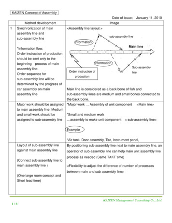
Design For Manufacturing/Assembly (DFM, DFA, DFMA)Much of the early and significant work on DFM and DFA was done in the early 1970s byBoothroyd and Dewhurst. Traditionally, product development was essentially done inseveral stages. The designer(s) (who usually had very good knowledge of materials,mechanisms, etc.) would design the product, and sometimes would construct workingprototypes. Once the prototype was tested and approved, the manufacturing team wouldthen construct manufacturing plans for the product, including the tooling etc. Often,different materials (e.g. different thickness or type of sheet metal), and differentcomponents (e.g. different sized screws etc), would be substituted by the manufacturingteam. Their goal was to achieve the same functionality, but make mass production moreefficient. However, the majority of the design remained unchanged, since themanufacturing engineers could never be sure whether a change would affect somefunctional requirement.Two things changed in the 1970’s:(i) Many new types of plastics were developed, and injection moulding technologybecame widely available, resulting in the possibility of low cost plasticcomponents. An advantage of these new plastic materials was that they provideddifferent material behaviour (e.g. many cycles of large elastic deformationswithout failure – a property useful in making snap-fit mating components). Thuspats that had to be made form metal and screwed together could just be made outof plastic and snap fitted. This reduced assembly time, assembly components, andproduction costs.(ii) Several companies were trying to bring their products to the market faster. Oneproblem with the earlier method of doing things was that each time there was adesign change made by the manufacturing engineer, product development washeld up, waiting for the engineering change notice (ECN) to be approved by thedesigner. Often, this process introduced delays because the design engineerwould be busy with other tasks, or unavailable. To avoid this, the concept ofconcurrent engineering (CE) became popular. The idea here was that acombined team of engineers and management would be assigned to each newproduct. This team may consist of mechanical designers, electrical engineers,software engineers, production engineers, marketing and sales, and management.Thus, as the design was being generated by the designers, the production peoplewould give feedback about feasibility to manufacture, more economicalalternatives etc. At the same time, sales people would negotiate of productoutlook and features, and so on. The biggest advantage of CE was that the1
product was designed in a way that manufacturing cost and time would be lowduring production.At this time, working with many different companies, Boothroyd’s team analysed existingdesigns of hundreds of products, and suggested design improvements based onmanufacturing and assembly ease. Using the experience of these projects, they thendeveloped a very large set of guidelines on how to estimate whether a design wasdesigned well (from a manufacturing point of view), and potential methods to improvethe designs.In subsequent years, the idea of DFM and DFA were extended to include other aspects ofbetter designs – including design for maintenance, design for environment, design forcost, etc. Often, this application of CE is referred to as DFX, where X is a variableselected from the set {manufacture, assembly, }. We shall restrict our study ofmanufacturing decisions to those related to fabrication and assembly.ManufacturingFabrication OperationsMaterialAssembly OperationsGeometryToleranceFigure 1. Effects of design (materials, geometry, tolerances) on manufacturingEffects of Tolerance on FabricationTight tolerances will requireMore care to be taken during machining Î larger processing timeHigher reject ratesMore expensive measurement/inspection systemsRestricted set of machine tools ( so . ?)Effects of Geometry on FabricationDifferent geometry (due to different design of product/part) will mean:Different process plansDifferent raw material costs (why ?)Different processing costs2
Example:[source: Boothroyd 91]Figure 2. Different components have different production costsEffect of Material on FabricationDifferent materials of designed part implies:Different process plansDifferent fabrication processesExamples ?Effects of Geometry, Material, Tolerance effects on AssemblyBoothroyd et. al studied many of these to compose a systematic methodology. Theemphasis was to relate Product design, Assembly operations, and Assembly Method tothe single decision factor: the cost. We shall study the Boothroyd method in detail. Notethat there are other systems based on very similar principals: The Hitachi AssemblyEvaluation Method, developed at Hitachi in Japan, used very similar ideas.Basic idea: reduction of cost of a product through simplification of its design.How ?- Reduction of number of components- Ensuring that parts are easy to assemble- Increasing the use of standardized parts across entire product range- Designing with widest possible tolerances- Material selection must consider manufacturing also, not just function.3
Why do these ideas work ?Fewer components in a design imply:Manual assembly:Fewer assembly operations Æ fewer assembly workersAutomated assembly:Reduction of one entire section of Assembly stationFewer fixtures/jigs, feeders, etc.Also, fewer parts usually mean smaller stacked tolerances, and therefore lead to betterfunctioning of the assemblies, and fewer rejects (why ?)The Boothroyd-Dewhurst method includes:Preliminary (rough) designSelection of Assembly Method (manual, robotic, or high-speed automated)Design/Redesign of product for selected methodThe selection of assembly method must be done at an early stage in the product designprocess (why?). One factor that affects this decision is the production volume (that is,forecast demand).Low volume ( 1000 parts per year) manual assemblyHigh volume ( million parts per year) high-speed automated assemblySomewhere in between these limits, and based on some other considerations (labourcosts, technical requirements, e.g. in spray painting) robotic assembly may be optimal.Typical hardware involved in each method, and its characteristics are listed below.Manual Assembly:Benches or simple conveyorsAssembly station has bins with un-oriented partsSimple jigs and fixtures with manual clampingSimple, light tools (manual/pneumatic/electric screwdrivers, solder irons etc.)Inexpensive setup costsAssembly costs are nearly constant, and independent of volume (why ?)4
High-speed (Special Purpose) Transfer Assembly:Machines are built to produce specific product.Components:Part feeders [indexed/asynchronous]Single purpose workheadsTransfer devices (usually equipped with workheads)Very expensive and time-consuming to buildVery high production rateDown time due to defective parts may be a severe problem[Example: defective part-mix in a bowl-feeder]Implication: incoming QC must be stringentInflexible: changing hard-automation system requiresjigs/fixtures/machines and may take a long time and cost a lot.fabricationofnewRobotic AssemblySimilar to non-synchronous special purpose assembly stations, except robots replace thesingle-purpose workheads.Use of robots allows flexibility in product types and production rates.Figure 3. Common assembly automation devices [source Boothroyd 91]5
Design for Manual AssemblyThe Boothroyd Dewhurst method provides a quantitative measure called the designefficiency based on analysis of a product. The efficiency compares the total assemblytime for a product with the total assembly time for an ideal product (determined by amethod suggested by the authors). The efficiency can be used to compare various designsin terms of their relative efficiencies (for manual assembly).The design improvement is brought about by two considerations:1. A decision is made as to whether the part can be considered a candidate forelimination, or combination with other parts of the assembly2. An estimation of the time taken to grasp, manipulate, and insert the part.The procedure:STEP 1. Obtain design detailsEngineering drawings, or Exploded 3-D views, or Existing product, or PrototypeSTEP 2. Take assembly apart (or imagine doing so) -- assigning identification to eachpart as it is removed.Consider sub-assemblies as parts, and analyse them separately (recursively).STEP 3. Begin re-assembly of the product. Start with the part with the highestidentification number, going all the way up to the part 1.Fill up the assembly worksheet as you go along.[note: the method requires that the product is assembled one part at a time. In reality,assembly workers use both hands and often assemble two parts in a step. However, achange in the assembly procedure will correspondingly change the assembly time for theideal product -- thereby keeping the efficiency constant.]STEP 4. Compute the design efficiency, given as:EM 3 x NM / TM6
We go through an example to see how the method works.Figure 4. A piston-assembly design [source Boothroyd 91]The computation is done by systematically completing the data in the following table.The data requires several estimates for assembly efficiency of different components basedon their characteristics. This data is compiled empirically – by a large number of timemotion studies conducted over may years. We will use the charts from Boothroyd(handouts given in class).7
c1c2c3c4c5c6c7c8c9Part IDNo of times theoperation is carriedout consecutivelyManual handling codeManual handlingtime per partManual insertion codemanual insertiontime per partOperation timec2( c4 c6)Operation cost0.4 c7Estimation fortheoretical minimumpartsTotal:TMCMNMName ofAssemblyDesign efficiency 3 NM/TM Table 1. Table for computation of Design efficiency (Source: Boothroyd 91).One of the key features of the Boothroyd-Dewhurst method is estimation of the idealproduct -- which translates to the method of filling up column 9 in the chart. They givethe following guidelines:Rule 1. During operation of the product, does the part move relative to all other partsalready assembled?Rule 2. Must the part be of a different material than the parts already assembled? [Onlyfundamental reasons associated with material properties are acceptable.]Rule 3. Must the part be separate from all parts already assembled (because otherwisenecessary assembly/disassembly of other parts would be impossible)?If the answer to any of these questions is YES, a 1 is entered in column 9 (except if thereare multiple parts in column 2, in which case the minimum number of separate partsrequired is entered in column 9.)8
Name ofEstimation fortheoretical minimumpartsc9AssemblyOperation cost0.4 c7c8Operation timec2( c4 c6)c7manual insertiontime per partc6Manual insertion codec5Manual handlingtime per partc4Manual handling codec3No of times theoperation is carriedout consecutivelyc2Part IDc161301.95001.53.451.381MAIN 1PISTON .540COVER12111.8398.016.66.640SCREW40.75 16.34TMNMDesign efficiency 3 NM/TM 0.29Total:CMPNEUMATICPISTONTable 2. Evaluating the design efficiency of PistonImproving the design:The following considerations are important:STEP 1. Is the number in column 9 the number in column 2 ?If yes, there is an opportunity for reduction in number of parts.STEP 2. Examine columns 4 and 6. These figures indicate potential for assembly timereduction.Based on these ideas, a redesign of the piston assembly is presented below. Notice howthe new design presents a design efficiency of 90%.9
Figure 5. An improved piston design [Source: Boothroyd 91]Name ofEstimation fortheoretical minimumpartsc9Operation cost0.4 c7c8Operation timec2( c4 c6)c7manual insertiontime per partc6Manual insertion codec5Manual handlingtime per partc4Manual handling codec3No of times theoperation is carriedout consecutivelyc2Part 81MAIN 341SPRING11101.5302.03.501.401COVER and STOP13.29 5.324TMNMDesign efficiency 3 NM/TM 0.90Total:CMTable 3. Evaluating the design efficiency of the re-designed piston10
Guidelines for improving design (for assembly) of mechanical products:1. Reduce Part Count and Part TypesWhy ?Lower material costReduced jigs/fixtures costImproved qualityLess documentationSmall inventoriesFewer suppliersSimplified production controlFewer InspectionsLess reworkHow ?1. Check the need for the part’s existence (apply the three rules above).2. Eliminate separate fasteners when possible.3. Design multi-functional parts by maximum use of the capabilities of individualmanufacturing processes. For example, use near-net shape moulding and casting whenpossible to reduce part count.4. Eliminate product features that are of no value to the customer.5. Do not over-use piece part producibility guidelines in early stages of design -- they leadto simplified production of individual parts, but much higher part count.Example: In figure 6, the single component design has potentially higher waste (since anirregular shape must be cut out of the stock sheet; but the assembly cost for the seconddesign is much higher.11
Figure 6a. Single componentFigure 6b. Two-component sub-assembly2. Try to Eliminate AdjustmentsWhy ?Adjustments require decision making during assembly (so ?)May lead to malfunctions after some usage by customer.How ?1. By elimination of parts.Example:2. Substitute electronic correction for mechanical adjustment.3. Use kinematic analysis to guide design rather than gut feeling.Examples (see figure 1)3. Design Parts to be Self Locating and AligningWhy?Ease of assembly12
Better performance of product close to breakdown (since parts tend to stay inposition rather than come out/off.)Why Not?Higher cost of manufacturing (more operations, in general)How?Figure 7. Some guidelines of design for ease of assembly4. Consider Access and Visibility for Each OperationWhy ?How?13
1. Ensure adequate clearance for hands, tools, testing probes etc.2. Ensure that the assembly worker has clear visibility of the mating features.5. Consider Handling Part from BulkWhy?Some parts are easily handled when alone, but create a mess when mixed in largenumbers.How?1. On parts that mate using interlocking tapers, include features that prevent nesting.2. On parts with combinations of holes, projections, gaps and cut-outs -- there is highprobability of tangling.Close gaps; Enlarge projections; Use closed-end coil springs;3. Avoid parts which are fragile or sharp, unless functionally necessary. If necessary,include safe-handling features.4. Avoid use of flexible parts -- if flexible parts are needed, try using those that retainshape when handled.5. Avoid parts that require special tools for the worker to perform assembly.6. Design Parts that Cannot be Installed IncorrectlyWhy?Example: Styrofoam packing for TV/Stereo.How?(a) Provide projections that will disallow incorrect assembly.14
(b) Make mating features asymmetrical.(c) Make parts symmetrical so that orientation is unimportant.(d) If two parts can be assembled incorrectly, ensure that assembly of some subsequentpart is impossible.(e) If all fails, mark part with assembly markers for identification.(f) Eliminate flexible parts that can almost always be assembled incorrectly.7. Eliminate Need for Reorientation During AssemblyWhy?Reorientation is an operation that adds no value to the assembly.How?Design products with single axis of assembly (usually, Exclusive Vertical Insertion is theideal).8. Maximize Part Symmetry, or Emphasize AsymmetryWhy?1. Higher symmetry implies lower orientation time/effortExample: Keys2. If the part cannot be made symmetric, then emphasized asymmetry allows us to reachthe correct orientation faster.Example ?References:Otto and Wood has a good chapter on DFMAProduct Design for Manufacture and Assembly, Geoffrey Boothroyd, Peter Dewhurst, Winston Knight, 2ndEdition, Marcel Dekker, New YorkSeveral figures in these notes are from the or1gonal Boothroyd and Dewhurst workbook:Product Design for Assembly, Geoffrey Boothroyd and Peter Dewhurst, 1991, Boothroyd Dewhurst Inc.15
Preliminary (rough) design Selection of Assembly Method (manual, robotic, or high-speed automated) Design/Redesign of product for selected method The selection of assembly method must be done at an early stage in the product design process (why?). One factor that affects this deci