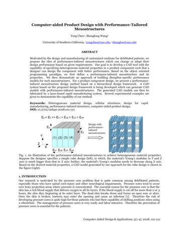
Transcription
ME 114Computer Aided EngineeringDrawing - IIAssembly Drawing ExercisesAsst.Prof.Dr.Turgut AKYÜREKÇankaya University, Ankara
Working Drawing/Production Drawing The drawings that are used to give information forthe manufacture or construction of a machine orstructure are called as working drawings orproduction ürekME 114 Computer Aided Engineering Drawing II– Assembly Drawing Exercises2/57
Working Drawing Working drawings must include all the knowledge for theproduction of a machine or structure explicitly so that nofurther information is required to complete the production.T.AkyürekME 114 Computer Aided Engineering Drawing II– Assembly Drawing Exercises3/57
Working Drawing Working drawings are specialized engineeringdrawings that provide information required to make thepart or assembly of the final design. May be more thanone sheet. Includes-Assembly drawing-Detail drawings ofnon-standard parts-Parts listT.AkyürekME 114 Computer Aided Engineering Drawing II– Assembly Drawing Exercises4/57
Assembly Drawing An assembly drawing shows how each part of adesign is put together. If the design depicted is only part of the totalassembly, it is referred to as 2.htmlT.AkyürekME 114 Computer Aided Engineering Drawing II– Assembly Drawing Exercises5/57
Constructing an Assembly Constructing an assembly begins with bringing in abase component. A base component will beselected because of its central role in defining theoverall assembly. Each successive component brought in needs to beoriented and located relative to other componentsin the assembly. Location and orientation is achieved by defininggeometric relations between geometric elements ofa component in the assembly and elements ofcomponents beeing brought in.T.AkyürekME 114 Computer Aided Engineering Drawing II– Assembly Drawing Exercises6/57
Content of Working Drawings for an Assembly An assembly or subassembly drawing showing all thestandard and nonstandard parts in a single drawing,drawn in their operating position A parts list or bill of materials, showing–––––detail number for each part,the quantity needed for a single assembly,the description or name of the part,catalog number if it is a standard part,and the company part number A title block Detail drawings of each nonstandard partT.AkyürekME 114 Computer Aided Engineering Drawing II– Assembly Drawing Exercises7/57
Assembly Drawing Content All the parts drawn in their operating position A parts list or bill of materials, showing–––––detail number for each part,the quantity needed for a single assembly,the description or name of the part,catalog number if it is a standard part,and the company part number Leader lines with balloons, assigning each part a detailnumber, in sequential order and keyed to the list of partsin the parts list Machning and assembly operations and criticaldimensions related the functions.T.AkyürekME 114 Computer Aided Engineering Drawing II– Assembly Drawing Exercises8/57
Standard Parts Standards parts are commonly used inassemblies.––––T.AkyürekThreaded fastenersNon-threaded fastenersGearsKeysME 114 Computer Aided Engineering Drawing II– Assembly Drawing Exercises9/57
Kinds of Assembly Drawings Pictorial assembly drawings Outline assembly drawings Sectioned assembly drawingsT.AkyürekME 114 Computer Aided Engineering Drawing II– Assembly Drawing Exercises10/57
Kinds of Assembly Drawings Pictorial assembly drawingsThese drawings are very useful to indicate the method ofassembly, and are often used in technical manuals. Outline assembly drawings Sectioned assembly drawingsT.AkyürekA Model Created as anIllustration for MaintenanceHandbooksME 114 Computer Aided Engineering Drawing II– Assembly Drawing Exercises11/57
Pictorial Assembly Drawings Pictorial assemblydrawings give generalgraphic description of eachpart and uses center linesto show how the parts areassembled. The pictorial assembly isnormally an isometric viewand is used in installationand maintenance manuals.T.AkyürekME 114 Computer Aided Engineering Drawing II– Assembly Drawing Exercises12/57
Pictorial Assembly Drawings With 2-D CAD, pictorialassembly drawings can becreated using traditionaltechniques. A 3-D CADmodel also can be used torender and create pictorialassemblies by positioningeach part in a pictorialview. Center lines and a partslist are added to completethe drawing.T.AkyürekME 114 Computer Aided Engineering Drawing II– Assembly Drawing Exercises13/57
Kinds of Assembly Drawings Pictorial assembly drawings Outline assembly drawings– give general graphic description of the exteriorshape.– are used for parts catalogs and installation manuals,or for production if the assembly is simple.– Therefore, keep number ofviews minimum necessaryto describe the assembly.– It is common to have asingle orthographicassembly view, such asthe front view. Sectioned assembly drawingsT.AkyürekME 114 Computer Aided Engineering Drawing II– Assembly Drawing Exercises14/57
Outline AssemblyFixture AssemblyT.Akyürekhttp://odin.me.memphis.edu/ugs docs/NX3/draftingeff/drawing types/inprocess drawings.htmlME 114 Computer Aided Engineering Drawing II– Assembly Drawing Exercises15/57
Kinds of Assembly Drawings Pictorial assembly drawings Outline assembly drawings Sectioned assemblydrawings– For determining howcomplicated devices areassembled,– For design visualization.T.AkyürekME 114 Computer Aided Engineering Drawing II– Assembly Drawing Exercises16/57
Sectioned Assembly Drawings Sectioned assembly drawings give generalgraphic description of the interior shape bypassing a cutting plane through all or part ofthe assembly. The sectioned assembly is usually amultiview drawing of all the parts, with oneview in full section (or half section, or brokenout section etc.).T.AkyürekME 114 Computer Aided Engineering Drawing II– Assembly Drawing Exercises17/57
Sectioned Assembly Drawings Reminder on section views:–Standard parts, such as fasteners, dowels, pins,bearings, and gears, and nonstandard parts, suchas shafts, are not sectioned; they are drawnshowing all their exterior features.– Adjacent parts in section are lined at differentangles, using the cast iron or other type of symbol.–Thin parts, such as gaskets, are shown solid black.T.AkyürekME 114 Computer Aided Engineering Drawing II– Assembly Drawing Exercises18/57
Sectioned /3DModeling.htmT.AkyürekME 114 Computer Aided Engineering Drawing II– Assembly Drawing Exercises19/57
Sectioned ME 114 Computer Aided Engineering Drawing II– Assembly Drawing Exercises20/57
Exploded Assembly Drawing One common variation on the assembly drawing is the exploded assemblydrawing: This can be either a pictorial or an orthographic assembly drawingin which the parts are shown exploded apart from each other.Exploded CompassAssembly DrawingT.AkyürekME 114 Computer Aided Engineering Drawing II– Assembly Drawing Exercises21/57
Creating Assembly Drawings How to create an assembly drawing?–An assembly drawing is produced bytracing the needed views from the detaildrawings, or by creating the drawing fromscratch.–With 2-D CAD, it is possible to copy detailviews, then place them on the assemblydrawing.–With 3-D models, simply assemble all themodels, then determine the line of sight toextract the needed assembly view (recall thevideo at the beginning of the course).T.AkyürekME 114 Computer Aided Engineering Drawing II– Assembly Drawing Exercises22/57
Creating Assembly Drawings Dimensions are not shown on assemblydrawings, unless necessary to provide overallassembly dimensions, or to assist machiningoperations necessary for assembly. Hidden lines are omitted in assemblydrawings, except when needed for assembly orclarity.T.AkyürekME 114 Computer Aided Engineering Drawing II– Assembly Drawing Exercises23/57
Parts List (Bill of Material)Parts List should include informationsuch as: Item or part number. Description or name of part. Quantity required. Material specification. Drawing number of detaildrawing if required. Stores or part reference number,if applicable.T.AkyürekME 114 Computer Aided Engineering Drawing II– Assembly Drawing Exercises24/57
Parts List (Bill of Material)Standard parts list The parts list runs vertically for as manyrows as are needed to list the parts.T.AkyürekME 114 Computer Aided Engineering Drawing II– Assembly Drawing Exercises25/57
Parts List (Bill of Material)T.AkyürekME 114 Computer Aided Engineering Drawing II– Assembly Drawing Exercises26/57
Part IdentificationBalloons in an assemblyBalloons are used to identify parts bytheir assigned number in the assembly.Part name in a detail drawingT.AkyürekIn detail drawings of an assembly,the part name and detail numberare located near one of the viewsME 114 Computer Aided Engineering Drawing II– Assembly Drawing Exercises27/57or title block.
Tabular DrawingsTabular drawings are used when several similar partshave common features.Tabular drawing of ancylinder, from a Paris catalogT.AkyürekME 114 Computer Aided Engineering Drawing II– Assembly Drawing Exercises28/57
Classic Problem 11.1:Sliding-Door Guide1. Sketch orthographic views of each part, with dimensions.2. If dimensions are missing, determine what they should be bytheir relationship to other parts.3. Determine tolerances as noted or assigned.4. Create 3-D models of each part, then extract orthographicviews.5. Determine finished surfaces and mark them on the sketch.6. Create dimensioned detail drawings of each non-standardpart in the assembly.7. Create an orhthographic or exploded pictorial assemblydrawing in section.8. Label all parts in the assembly drawing, using numbers andballoons.9. Create an ASME standard parts list with all relaventinformation for the parts in the assembly.T.AkyürekME 114 Computer Aided Engineering Drawing II– Assembly Drawing Exercises29/57
Problem 11.2:Quick-Acting Hold-Down Clamp1. Sketch orthographic views of each part,with dimensions.2. If dimensions are missing, determinewhat they should be by theirrelationship to other parts.3. Determine tolerances as noted orassigned.4. Create 3-D models of each part, thenextract orthographic views.5. Determine finished surfaces and markthem on the sketch.6. Create dimensioned detail drawings ofeach non-standard part in theassembly.7. Create an orhthographic or explodedpictorial assembly drawing in section.8. Label all parts in the assembly drawing,using numbers and balloons.9. Create an ASME standard parts list withall relavent information for the parts inthe assembly.T.AkyürekME 114 Computer Aided Engineering Drawing II– Assembly Drawing Exercises30/57
Problem 11.2:Quick-Acting Hold-Down ClampT.AkyürekME 114 Computer Aided Engineering Drawing II– Assembly Drawing Exercises31/57
Problem 11.2:Quick-Acting Hold-Down ClampT.AkyürekME 114 Computer Aided Engineering Drawing II– Assembly Drawing Exercises32/57
Plate AssemblyT.AkyürekME 114 Computer Aided Engineering Drawing II– Assembly Drawing Exercises33/57
Plate AssemblyT.AkyürekME 114 Computer Aided Engineering Drawing II– Assembly Drawing Exercises34/57
Plate AssemblyT.AkyürekME 114 Computer Aided Engineering Drawing II– Assembly Drawing Exercises35/57
Plate AssemblyT.AkyürekME 114 Computer Aided Engineering Drawing II– Assembly Drawing Exercises36/57
Trombon AssemblyT.AkyürekME 114 Computer Aided Engineering Drawing II– Assembly Drawing Exercises37/57
Trombon AssemblyT.AkyürekME 114 Computer Aided Engineering Drawing II– Assembly Drawing Exercises38/57
Bearing BlockT.AkyürekME 114 Computer Aided Engineering Drawing II– Assembly Drawing Exercises39/57
Bearing BlockT.AkyürekME 114 Computer Aided Engineering Drawing II– Assembly Drawing Exercises40/57
Bearing BlockT.AkyürekME 114 Computer Aided Engineering Drawing II– Assembly Drawing Exercises41/57
Hitch MountT.AkyürekME 114 Computer Aided Engineering Drawing II– Assembly Drawing Exercises42/57
Hitch MountT.AkyürekME 114 Computer Aided Engineering Drawing II– Assembly Drawing Exercises43/57
Hitch MountT.AkyürekME 114 Computer Aided Engineering Drawing II– Assembly Drawing Exercises44/57
Hitch MountT.AkyürekME 114 Computer Aided Engineering Drawing II– Assembly Drawing Exercises45/57
Tower AssemblyT.AkyürekME 114 Computer Aided Engineering Drawing II– Assembly Drawing Exercises46/57
Tower AssemblyT.AkyürekME 114 Computer Aided Engineering Drawing II– Assembly Drawing Exercises47/57
Tower AssemblyT.AkyürekME 114 Computer Aided Engineering Drawing II– Assembly Drawing Exercises48/57
Tower AssemblyT.AkyürekME 114 Computer Aided Engineering Drawing II– Assembly Drawing Exercises49/57
Tower AssemblyT.AkyürekME 114 Computer Aided Engineering Drawing II– Assembly Drawing Exercises50/57
Roller Guide AssemblyT.AkyürekME 114 Computer Aided Engineering Drawing II– Assembly Drawing Exercises51/57
Roller Guide AssemblyT.AkyürekME 114 Computer Aided Engineering Drawing II– Assembly Drawing Exercises52/57
Roller Guide AssemblyT.AkyürekME 114 Computer Aided Engineering Drawing II– Assembly Drawing Exercises53/57
Roller Guide AssemblyT.AkyürekME 114 Computer Aided Engineering Drawing II– Assembly Drawing Exercises54/57
Roller Guide AssemblyT.AkyürekME 114 Computer Aided Engineering Drawing II– Assembly Drawing Exercises55/57
Roller Guide AssemblyT.AkyürekME 114 Computer Aided Engineering Drawing II– Assembly Drawing Exercises56/57
English – Turkish DictionaryWorkingdrawingUygulama çizimi,ayrıntılı çizimProductiondrawingİmalat resmiAssemblydrawingMontaj resmispecificationsşartnameblueprintOzalit baskısı,ayrıntılı planBill of materialMalzeme listesiTitle blockİsim bloğuDetail drawingAyrıntı çizimi,detay resmisubassemblyAlt montajSurface finishYüzey ingbirleştirmeDegree offreedomSerbestlik derecesimillingfrezelemecutterKeski, kesicifixtureBağlama düzeniWorm gearSonsuz vida dişlisiidleavarevalveVana, subapsprocketZincir dişlisi, cerdişlisispringyayClamping unitKıskaç, ekME 114 Computer Aided Engineering Drawing II– Assembly Drawing Exercises57/57
Kinds of Assembly Drawings Pictorial assembly drawings Outline assembly drawings -give general graphic description of the exterior shape. -are used for parts catalogs and installation manuals, or for production if the assembly is simple. T.Akyürek ME 114 Computer Aided Engineering Drawing II- Assembly Drawing Exercises