Transcription
Modeling for GazeboA Design Guide for Proper Exporting from Solidworks for Gazebo Simulation
ContentsTable of Figures . iiRead me . 1What is Gazebo? . 1File Types: URDF and SDF . 2Solidworks Concepts . 2Supported Links . 3Collision vs. Visual Models . 5Design Practices: . 8The Exporter . 15Sample export procedure . 18Current Exporter Tips and Tricks . 24Known Bugs (and possible solutions) . 25i
Table of FiguresFigure 1: the folder with all the robot data and the contents of a URDF. . 1Figure 2: Various coordinate systems in a robot . 3Figure 3: Revolute joint import test . 3Figure 4: Prismatic joint import test . 4Figure 5: Free and Planar joint import test . 5Figure 6: This wheel has a lot of detail that is not required to simulation . 5Figure 7: Gears bot Visual model (left) and collisional model (right) . 6Figure 8: A Block driven wheel that has shifted positions . 9Figure 9: A block driven arm that has shifted positions . 10Figure 10: image showing the toolbar where Fit View can be found. 10Figure 11: A center rectangle: 6" by 1" to be used as the robot chassis . 10Figure 12: 2 3" Diameter circles added to the sketch, these will be the wheels . 11Figure 13: A figure showing the redundant dimmnsions . 11Figure 14: A figure showing the 3 blocks . 12Figure 15: Top view of chassis with new sketch added . 13Figure 16: Finished model. 14Figure 17: Model with some dimensions changed . 14Figure 18: LEGO Car model . 18Figure 19: Side view showing the sketch of the collisional model . 18Figure 20: Coordinate system is along axis . 19Figure 21: all coordinates are labeled . 19Figure 22: Exporter and Truck. The collisional model is the transparent body around the model . 20Figure 23: The exporter with all parameters for the wheel set . 20Figure 24: The tree structure of the assembly . 22Figure 25: A picture showing the relative sizes of the collisional and visual STL files . 22ii
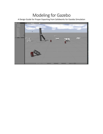
Read meThe purpose of this document is to guide the user through the set-up, export from Solidworks,post processing, and import into Gazebo of a feasible robot model. Feasible models are ones that onlycontain revolute, continuous, prismatic, free, and fixed joints, and do not contain N-bar linkages where aseries of links connect back to a link previously in the chain. Topics covered include: An introduction toGazebo and the special file formats it uses, types of joints, top-down and bottom-up design practices,and procedures for bringing a Solidworks assembly through the entire process to gazeboWhat is Gazebo?Gazebo is a simulation environment that allows for testing of complex systems – robotic orotherwise. It has many uses, including testing the dynamics of a control system before the system hasbeen actualized. You can also use it to test new code or physical systems that might be too dangerous orexpensive to test in the real world.Our goal is to highlight the key processes involved in taking a CAD model in Solidworks andbringing it through the exportation process into Gazebo for testing. There are many minute details thatmust be attended to if you are to come out with a system that looks or works anything like the one youintended.Figure 1: the folder with all the robot data and the contents of a URDF.1
File Types: URDF and SDFThe original file for performing simulation is the Universal Robot Description Format, or URDF.This xml-like file type is used heavily in ROS for simulation and testing; it is a supported file type for rvizand other ROS tools. The file is a tree structure of child links (like wheels and arms) connected to parentlinks (like the chassis) by a series of joints.Tree Limitations:This file is the description of how yourBecause of the tree structure, there are limitationssystem moves internally, and this willinvolving recursion that can make some systems difficult-ordetermine how it can interact with theimpossible- to model. For example, think about how youenvironment. The capabilities of the filewould model a four-bar linkage using a tree structure. Thehowever are limited in comparison to thebase link would connect to the crank, which connects tonew Simulator Description Format, or SDF.the floating link, which connects to the rocker. However,SDF files are what Gazebo uses whenthe base link is the parent, so it cannot be the child of theperforming simulation, and in fact beforerocker. To overcome this dilemma, you can use specialimporting one of your URDF models, it willGazebo tags to enable more of a map-like structure,convert it into an SDF. This file formatcreating an invisible link between the rocker and base.includes more details like friction, damping,and environment properties likeheightmaps and lights that are excluded from the URDF file. That being said, we will start with the URDFexporting process because of the useful SW2URDF plugin available for Solidworks users. This allows youto manually piece together a URDF file for use in simulation, and we will be looking at that processshortly.Solidworks ConceptsCoordinate Frames / OriginsCoordinate Frames are a key concept for standard system control problems, and are justreference points which you can use to keep track of a body’s 6-DOF position and orientation. In therealm of URDF models, there are three types of origins that you need to be familiar with. An origin thatis built into the child link in a URDF tree is known as a Child Origin. You can see on wheel D in Figure 2that the origin moves with the child link (the wheel) and is rotated. An origin built into the parent bodyis a Parent Origin, and can be seen on the main body on the robot at the right. The last type of origin isthe Global Origin. This is an origin built at the assembly level, as can be seen below the robot. This is animportant origin because it is what relates the initial position of the robot in space to its spawn locationin Gazebo, in addition to whatever link relations you apply during the export process (for examplecreating a prismatic joint which references the global origin).2
Figure 2: Various coordinate systems in a robotAxesAn Axis is a line oriented in space, used as a reference for motion. Revolute and Continuousjoints will rotate around axes, and prismatic joints will translate along axes. Just like Origins, Axes can bein the child, parent, or global frame.Supported LinksThe four kinds of links supported by the SW2URDF exporter are Revolute, Prismatic, Continuous,and Fixed. Each requires special attention to how they are exported to make sure they work as intended(as you can see below, where a series of 9 joints was exported each with a different set of parentcoordinates, resulting in only three viable prismatic joints).RevoluteA revolute joint is a 1-degree-of freedom joint that allows rotation about a single axis. It can beused to describe an arm or hinge joint. It is capable of multiple rotations, but allows for joint limitationsso that you could restrict the motion to a 90 degree arc, for example. To properly export a Revolutejoint, the origin must be on the child link. In other words, when selecting your origin during the exportprocess, the origin must be on the link that will be rotating (for example, a wheel). The actual axis ofrotation can be in the parent link, the child link, or in the global frame and the joint will still operateproperly. It is worthwhile to note here that if you do not enter limits for your joint, then it will not move.Figure 3: Revolute joint import test wheels D and F failed while C works3
If you do not specify a lower and upper angular bound in addition to a force and velocity limit, thenthese will go in as zeroes and the link can only move zero radians at zero radians per second! (that is tosay not at all)PrismaticA prismatic joint is a 1-degree of freedom linear translating joint. It allows for translation alongan axis, but not rotation around the axis. There is an SDF joint called Piston that allows for that kind ofmovement, but that is not avail bile through the current exporter. To properly export a prismatic joint,the origin must be from the global frame. In Solidworks, that means the origin at the Assembly level. Theprismatic axis (the axis along which the part will translate) can be in the child link, the parent link, or inthe global frame and the link will still operate properly. It is worthwhile to note here that if you do notenter limits for your joint, then it will not move. If you do not specify a lower and upper bounds as wellas a force and velocity limit, then these will go in as zeroes and the link can only move zero meters atzero meters per second!Figure 4: Prismatic joint import testContinuousA continuous joint is best represented by a wheel, which can rotate continuously. Similar torevolute joints, a proper continuous joint will have the origin on the child link. The axis can be in theglobal, child, or parent frame. This joint does not require velocity and effort limits but it isn’t a bad ideato include them just in caseFixedA fixed joint is used when you want a child link to be incapable of movement with respect to theparent link. In other words, the link is fixed. A proper fixed link makes use of a global origin, otherwise itwill export in an erroneous location. This joint does not require limits of any type.Planar and FloatingIf you decide after hitting the Preview and Export button that you want to change the link type,you will want to change it in the Joint Editing page. If you click the pull down menu on this page, youmight notice that you have two more options than before: Planar and Floating joints. Currently theseboth do the same thing, where the link generated is free from the parent body, disconnected andunrelated to it. You can use these kinds of links if you want to import multiple free bodies into thesimulator. Remember though, that if you want to be able to manipulate one of these free bodies withthe main robot model, you would need to enable internal collision detection because the body is4
considered part of the robot even though it does not maintain a physical relationship with the parentbody.Figure 5: Free and Planar joint import testCollision vs. Visual ModelsShown below is the AndyMark 4” wheel used in the standard FRC Kitbot. This wheel may notseem that complicated, but if you tried to use if as-is for simulation, you would quickly realize that ittakes a lot of effort to check the collision models of complex parts! A collision model is the model thatGazebo references when the robot comes in contact with anything in the simulator. The simulator has tomake sure that when your robot goes to grab something, it doesn’t just pass right through it. To do this,it checks the faces of your collision models to see if they are intersecting anything. If you tried to use theraw wheels from CAD, you would likely get a drastically reduced real-time factor; I’ve gotten down to0.00% real-time when trying to simulate a robot straight from export. The key is in how complex thepart is. This wheel as shown on the far-right has over 18,000 faces! That’s just too much for thesimulator to handle when it is checking for collisions with your model.Figure 6: This wheel has a lot of detail that is not required to simulationThe secret to creating a useable model for simulation lies in having different files for you Visual andCollision models. A visual model only has to be rendered on the screen, so a complex shape like the oneabove is fine. The collision for the AndyMark wheel only needs to be a rough cylinder for the model to5
work as intended. As you can see below, if you can render the robot you wish to model using a verysimple series of geometric shapes, then the simulator will have a much easier time and you will seefaster real-time factors. Deciding what you want to use for Collision models is no easy task. You wantthe simplest form that will mimic how the system is supposed to operate, but will not overburden thesimulator’s processing. The simplest shape to render is a tetrahedron, because it can be rendered withonly four faces. But this kind of shape would be all but useless as a wheel, because it wouldn’t roll! It willtake some practice and maybe even some testing to determine what the best option is. There willalways be a tradeoff between collision accuracy and model simplicity. If complex geometry is requiredfor proper dynamics, be ready to sacrifice simulation speed.Figure 7: Gears bot Visual model (left) and collisional model (right)Every Collision model will have different needs to fulfill but there are some good guidelines to follow.1. Group Rigid bodies togetherAny group of parts that does not move relative to each other is considered a rigid body. Base yourcollisional models around these and not the individual parts inside of them. For example the motor onan arm or claw does not need a separate collisional model it would be part of the arm it was attached to2. Use only what you need.Remember that only outside surfaces of your model are important to collisions so unless theresomething inside that you need to worry about the inside geometry can be ignored. For instance aclosed cardboard box is hollow inside but the collisional model can be solid to reduce the complexity ofthe geometry.3. Basic shapes work best.If the intent of you collisional model can be captured with a box or a cylinder, use those! A cylinder is1000x smaller (file size wise) than the wheel above.4. It can be ok for your collisional models to collide6
If you are not planning on using internal collisions in your model it is perfectly fine to have collisionalmodels intersect as shown by the wheels and body of Gearsbot, above.With the current exporter, there is no way to export collision and visual models simultaneously.The best method we have come up with so far is to export two models, one which is all visual and onewhich is collisional. The best way to do this is to save a copy of the assembly with collisional parts in itand use the second model to export the collisional model. This will save the trouble of having toconstantly change the export configuration. If you place the collisional models directly over the visualmodel as shown above, Then creating the combined robot is as “easy” as combining the URDF files. Thefiles contain positions for different types of models, and so when you export the visual model thesection under visual and also the section under collision will both be the visual model. It’s the same casefor the collision model, so by taking the collision model link elements and replacing the one if the visualfile with them, you create a combined file. Note that you will have to update the file paths for the STLfiles associated with the links. You can choose to manage different folder locations but it is perhapseasier to copy all of the block collisional parts to the meshes folder of the visual model. Just make surethe file names are different! Once you do this you should be able to open your robot in Gazebo and seeif your links are in the right place. If you see that your collision models are not in the same place as thevisual models, there may be an error with your origins in the Solidworks model. To make your life easier,you should try to place the origins of the visual and the collision model in the same place, as this willguarantee that they come in in the right spot.7
Design Practices:When it comes to design methodologies, there are two basic types. The most common one isBottom-Up design, which is where you build subsystems and then piece them together to create a morefunctional system. If you were going to build a robot to pick up a ball using the Bottom-up method, youwould probably break into subteams and one group would build a drive train and another would build agripper and arm mechanism. Then the teams would get together and integrate their designs. A differentmethod of design is called the Top-Down strategy. A Top-Down strategy looks at the challenge as awhole, and then breaks it down into subcomponents, often using “black-boxes” and other fabricationsthat eliminate the need for focusing in on fine details. If you were to build the same robot using thisstrategy, there would be more planning involved and more communication between the groups beforeand during build, but then integration would go much faster because there was an overall blueprintfrom the start that was flushed out afterwards. Each of these methods lends itself to the exportationprocess differently, and so we will address them differently as well.Bottom-Up Design:This style of design assumes that you have a model of your robot complete, or that you haveacquired a robot model from another source. The first step in this design process is to clean up the robotmodel. To make the export process as easy as possible, you should generate your own Origins accordingto the joint rules mentioned above, in addition to axes. The usefulness of this step is that the exporterwill pull the names of these axes from your Solidworks document and you can select them from thedropdown instead of having to select them by hand. After that initial setup it is just a matter of goingthrough the export process, meaning selecting your link bodies, giving them names and origins, and thensetting their parameters like limits. Another thing to remember is to group solidworks parts intosubassemblies based on what parts move together and form rigid bodies. This will help in the exportprocess because selecting link elements will consist of only 1 or 2 clicks instead of having to select everypart individually!After you have successfully exported your model, you need to bring it into Gazebo. This involvesbooting into Ubuntu and configuring your files. You must first create a model.config file to be placed inthe root of the URDF package. A sample configuration file is shown below. For the full file, werecommend copying one of the configuration files from the existing models in you .gazebo folder (This isa folder in home, if you cannot see it press ctrl h to show hidden folders) and modifying it accordingly.Once you have the file created, you need to place your URDF package (the entire folder) in the modelsfolder. After that, it’s just a matter of running Gazebo and selecting your model from the list of availablemodels.8
Top-Down Design:Top-down design is when parts are defined in the context of the assembly. It is a method ofdefining a skeleton of the model and making it more detailed from there. The most common way ofdoing this in Solidworks is using blocks. Blocks are sketch elements that move as rigid bodies. They canbe edited, saved, resized, assigned mass properties and made into parts.Known issues and DrawbacksBlocks can be immensely helpful in prototyping a design there are however some drawbacks tousing them in this context: In order to be made into part the blocks must be made in what Solidworkscalls a layout sketch. Layout sketches can only be made on the front plane of a part or assembly there isno known setting to change this. All part and assemblies are limited to one layout sketch. If you insert alayout driven subassembly in a larger assembly the subassembly cannot be made flexible. What thismeans for robot modeling is that blocks can only be used to model your robot for all motion that can becaptured in a single plane so if you have a claw with a gripper at the end or an arm that moves in 3dimensions you cannot use blocks to design that. This severely limits the power of blocks for complexrobot applications. They can still be used for prototyping sub systems independently or it can be used asa jumping off point for complex robots.FAQParts made from Blocks jump to incorrect positionsRebuild the document. Edit Rebuild. Or press Ctrl BRebuild does not fix displaced partsThe cause of this is currently unknown. The apparent issue is that the blocks move and update the partblock Relation locking them in the new, incorrect position but the 3D solids themselves try to stay in thesame place creating issue like orbiting wheels and other offset geometry. To fix it you must suppress thepart made from the block and move the driving block in the layout sketch back to the correct positionFigure 8: A Block driven wheel that has shifted positions9
Another instance:Figure 9: A block driven arm that has shifted positionsModel disappears when rotating viewFit the model to view.This icon:Figure 10: image showing the toolbar where Fit View can be foundOr press the f keyGetting StartedThis is a step by step procedure to create a block driven tricycle robotYou may want to start by showing the Blocks toolbar; this will help you manipulate the blocks you make.You can find it with the other toolbars in View Toolbars Blocks1. Open a new Assembly .2. Close the Insert Components Command property window.3. Navigate to the Layout tab and select Create layout.Note: The layout is always created on the front plane. There is no way to change this.4. Create a Center Rectangle centered at the origin and Dimension the Rectangle as shown:Figure 11: A center rectangle: 6" by 1" to be used as the robot chassis10
5. Create 2 circles Horizontal with the origin, 1” away from the outside edges of the rectangle, and3” in diameter, shown below with relations.Figure 12: 2 3" Diameter circles added to the sketch, these will be the wheels6. Select the line segments of the rectangle by right-clicking on one of the segments and clickingSelect Chain.7. Click Make Block from either the Block toolbar or Layout pane.8. Click the Green Check Mark.9. The rectangle should now appear light gray, and the dimensions associated with it will beunsolvable or conflicted.Figure 13: A figure showing the redundant dimmnsions10. Delete the dimensions in question.11
Note: If all dimensions appear as normal exit the layout sketch and enter again by usingthe layout button on the layout Pane11. Add a Horizontal Constraint to the bottom edge of the rectangle.12. Make a block out of each circle following steps 9-12 for both of them.13.The resultant sketch should have 3 blocks and look like this:Figure 14: A figure showing the 3 blocksNote: the 6” dimension is for the centerlines they can be deleted as they add nothing tothe sketch.14. Right-Click Block1-1 from the Assembly Tree, Choose 'properties' and change the name to“Chassis”.15. Click OK.16. Change the name of the left wheel to “Rear Wheel” and the right wheel to “Front Wheel”.17. Select the Chassis Block and click Make Part from Block from the Layout pane.18. Make sure On Block is selected under Block to Part Constraint.19. Click the Green Check Mark.Notice a new part has been added to the assembly.20. Edit the newly made part in the assembly21. Expand the part and select Sketch1.22. Click Extrude Boss/Base from the Features panel.23. Set the End Condition to Mid plane and the Depth to 4.12
24. Click the Green Check Mark.25. On the top plane of the chassis solid, sketch the following rectangle.Figure 15: Top view of chassis with new sketch 41.42.43.44.45.Select the Rear Wheel Block and click Make Part from Block from the Layout pane.Select Project as Block to Part Constraint.Click the Green Check Mark.Edit the new partExpand the part and select Sketch1.Click Extrude Boss/Base from the Features panel.Set the Depth to 1.Click the Green Check Mark.Mate the back face of the wheel to the front face of the chassis.Hold Ctrl, Click and Drag the wheel part to make a copy of the wheel.Mate the front face of the wheel to the back face of the chassis.Mate the cylindrical face concentric with the cylindrical face of the first wheel.Select the Rear Wheel Block and click Make Part from Block from the Layout pane.Select On Block as Block to Part Constraint.Click the Green Check Mark.Edit the new partExpand the part and select Sketch1.Click Extrude Boss/Base from the Features panel.Set the Depth to 1.Click the Green Check Mark.13
46. The finished model should look like this:Figure 16: Finished model47. To change the dimension of the blocks. You must enter the layout sketch, right click on the blockin question and choose edit.48. Edit the sketch of the front wheel and change the diameter to 2.75”49. Edit the height of the chassis to be .75” and the width to be 8”50. The model should now look like this:Figure 17: Model with some dimensions changedThis robot would not need a separate collisional model as these parts are very simple. Howeverthe point of blocks is to use them to prototype the skeleton of the robot and fill in the details later.14
The ExporterOnce the exporter is installed make sure that it is enable by going to tools add-insFigure 18: Insure the exporter is enabledExport as URDF is available from the file menu. There are three phases of the exporter the first partappears as a Property Manager window on the left side of the screen.Figure 19: the features of the top half of the exporter15
Figure 20: The bottom part of the exporter shows the tree structure of the modelThe second page of the exporter is the joint properties window where coordinate reference settings forthe joints can be changed and joint limits applied.Figure 21: The joint properties window16
The third step of the exporter is the link properties tab. The most important feature of this is to check tosee if the link has a proper inertia tensor in the top right-hand corner. If they are all 0 then you will haveto quit and re-export your model. You may want to change the mesh from course to fine but this oftenresults in a much more complex model for very little (if any) visual difference.Figure 22: The link Properties window17
Sample export procedureThis is a sample procedure for exporting a robot, in this case a LEGO truckFigure 23: LEGO Car modelThe collisional models for the wheels are cylinders. You can choose to make external parts to use ascollisional models or define them in the assembly. Here we have elected to do it in the assembly.We’ve decided that I need a good level of detail in the collisional model but not as much as the visualmodel is; a rectangular block will not do. Instead I have chosen to do a rough outline of the truck withparticular detail to the front back and underside of the truck because we are concerned with groundclearance for this particular model. We then simply extruded the outline to make the collisional model.We usually set the collisional model to air as a material just as a fast way to make it transparent.Figure 24: Side view showing the sketch of the collisional model18
Next up is coordinate systems and axesWe placed a coordinate system for each wheel at the assembly level using the origin of the wheelassembly which I
exporting process because of the useful SW2URDF plugin available for Solidworks users. This allows you to manually piece together a URDF file for use in simulation, and we will be looking at that process shortly. Solidworks Concepts Coordinate Frames / Origins Coordinate Frames are a key c