Transcription
Design For Manufacture and AssemblyHoward Gibson C.E.T., hgibson@eol.caLast updated 2021/12/02Contents1 Introduction12 General DFMA Principles13 Design Methodology3.1 Part Count . . . . . . . . . . . . . . . . . . . . . . .3.2 Assembly . . . . . . . . . . . . . . . . . . . . . . . .3.2.1 Handling Parts and Assemblies . . . . . . . .3.2.2 Fasteners . . . . . . . . . . . . . . . . . . . .3.2.3 Cables . . . . . . . . . . . . . . . . . . . . . .3.2.4 Poka Yoke . . . . . . . . . . . . . . . . . . . .3.3 Fabrication . . . . . . . . . . . . . . . . . . . . . . .3.3.1 Machining . . . . . . . . . . . . . . . . . . . .3.3.2 Sheet Metal . . . . . . . . . . . . . . . . . . .3.3.3 Welding . . . . . . . . . . . . . . . . . . . . .3.3.4 Casting . . . . . . . . . . . . . . . . . . . . .3.3.5 Rapid Prototyping – Additive Manufacturing3.3.6 Process Flow . . . . . . . . . . . . . . . . . .3.4 Service . . . . . . . . . . . . . . . . . . . . . . . . . .3.5 Documentation . . . . . . . . . . . . . . . . . . . . .3.6 Subcontracting . . . . . . . . . . . . . . . . . . . . .3.7 Infrastructure . . . . . . . . . . . . . . . . . . . . . .3.7.1 Design Change Rules . . . . . . . . . . . . . .3.8 Communication . . . . . . . . . . . . . . . . . . . . .3.9 Management . . . . . . . . . . . . . . . . . . . . . . .i.23356791011141616171819202021222223
3.9.1Concurrent Design . . . . . . . . . . . . . . . . . . . . 244 Design Skills and Tools4.1 Drafting . . . . . . . . . .4.2 Inspectability . . . . . . .4.3 Bills Of Material (BOMs)4.4 3D CAD . . . . . . . . . .5 Notes5.1 Size and Strength . . . . . . .5.2 Design of Covers . . . . . . .5.3 Style . . . . . . . . . . . . . .5.4 Lightweight . . . . . . . . . .5.5 Drawing Sizes and Lettering .5.6 More on Subcontracting . . .5.7 Office Politics . . . . . . . . .5.8 Lean Manufacturing . . . . .5.8.1 The Seven Wastes . . .5.8.2 The Five Questions for. . . . . . . . . . . . . . . . . . . . . . . . . . . . . . . . . . . . . . . . . . . . . . . . . . . . . . . . . . . . . . . . . . . . . . . . . . . . . . . . . . . . . . . . . . . . . . . . . . . . . . . . . . . . . . . . . . . . . . . . . . . . . . .Continuous 810121314232528List of Figures123456789101112Two Handed Assembly . . . . .Ratchet Drive Kit . . . . . . . .Please don’t . . . . . . . . . . .Box Assembly, No Cables . . .Box With Connectors . . . . . .Poka Yoke . . . . . . . . . . . .Part In Lathe . . . . . . . . . .Machined Assemblies . . . . . .Sheet Metal Box . . . . . . . .Who Has the Biggest Influence?Bad Drafting . . . . . . . . . .Hex Socket Head Cap Screw . .ii.
List of Tables12345Sheet Metal Tolerances. .Cap Screws on BOM. . . .Lifting Capability . . . . .Drawing Font Sizes. . . . .Mechanical Design Wastes.iii.1528313539
iv
11IntroductionDesigning something that can be assembled and used, may be sufficient forone-off shop equipment and proof-of-principle. In a cost competitiveproduction environment, it is not enough. We need product that that workswell, that is reliable, and that is easy and cheap to manufacture. Thisrequires significant effort by design and engineering, and an understandingof engineering principles, such as Design For Manufacture andAssembly (DFMA).DFMA is a strategy that reduces cost and improves quality.2General DFMA PrinciplesThere are a number of websites and articles that summarize rules forDesign For Manufacture and Assembly.[1]1. Simplify the design and reduce the number of parts.2. Standardize and use common parts and materials.3. Design for ease of fabrication.14. Design within process capabilities and avoid unneeded surface finishrequirements.5. Mistake-proof product design and assembly (poka-yoke)6. Design for parts orientation and handling.27. Minimize flexible parts and interconnections.8. Design for ease of assembly.9. Design for efficient joining and fastening.1The reference provides a long list of tips. Most of Product Design for Manufactureand Assembly[2] is about fabrication processes.2Again, the reference provides lots of suggestions.
23 DESIGN METHODOLOGY10. Design modular products.11. Design for automated production.312. Design printed circuit boards for assembly.3Design MethodologyCongratulations, you are the mechanical designer for your company’s newHandy Dandy Super Duper Nutating Widget! The widget you are todesign, requires custom parts to be fabricated. It requires catalogue partsand materials to be ordered. All parts must be stored in inventory untilthey are needed. The inventory must be searchable, and tracked byaccounting. The parts must be kitted. The widget must be assembled andtested. It must be moved safely around the plant. It must be packaged andshipped. The widget must get sold. The widget must be use-able by thecustomer. The widget may require service, possibly by the customer. Thewidget must eventually be disposed of.[3] You must communicate and workwith co-workers from other technical specialties, managers, andmanufacturing. You are part of a team. Mechanical design must accountfor all of this. All of your design decisions must be made in context of adesign strategy.DFMA requires a top-down design process, in which the designer looksfor solutions that meet all the requirements. The design review teamshould include the other designers on the project, and manufacturing, andsales, and any other stakeholders. You should model and document severaldesigns, to the point that you can evaluate performance and cost. Yourvery first idea ought to work, but it probably is not the best idea you cancome up with.3Product Design for Manufacture and Assembly[2] has a chapter entitled “Design forHigh-Speed Automatic Assembly and Robot Assembly”.
3.1 Part Count3.13Part CountDFMA manuals tell us to reduce the number of parts. Fewer parts meansfewer assembly steps, fewer fasteners, and reduced inventory.A typical widget contains parts that accomplish its basic functionality,and then a bunch of other pieces that connect everything together, andprovide protection, and possibly handling and/or mounting to otherequipment.There are a number of causes of excessive parts. . . Designers start from a base plate or some other existing structure,and they design a mount bracket for each and every part. You shouldbe trying very hard to mount everything directly to some primarybase or chassis. Designers are pressured to re-use existing parts and designs. This cansave tooling and inventory costs. It can also result in kludges. Allsorts of cost is generated by the design and fabrication of brackets toconnect components to holes that were not intended for thosecomponents. Parts are designed in sequence instead of all-together. A partdesigned early on is finalized, and fabricated, and cannot be modifiedto solve the DFMA and other design issues that come up later. Asnoted below , concurrent design is good practice.Each mechanical part should be made to do as many things as possible.Any part called “bracket” probably can be eliminated from your design.3.2AssemblyGood DFMA practice is for all parts to be mounted onto a stable base. Thestable base can be your widget’s primary structure. It can be your primarystructure mounted to an assembly fixture.4 It is very desirable that there4Note how the assembly fixture is not designed by manufacturing. It is an integral partof your mechanical design strategy. You may even need features in your widget to supportfixturing!
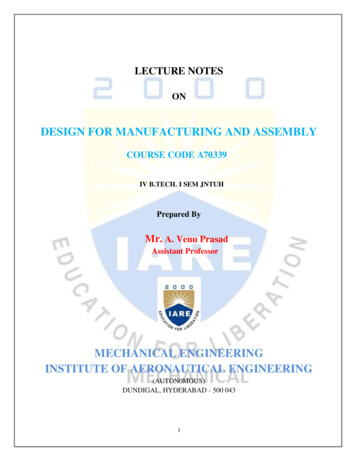
43 DESIGN METHODOLOGYFigure 1: Two Handed Assemblybe no need to flip the stable base over. It is nice if the base does not haveto be rotated on the work bench. Parts attached to the structure should beretained by gravity or by configuration, leaving both hands to managefasteners and tools.If your assembly is a stable base as noted above, you can use one handto hold the part, while the other holds a fastener and driver. The part mustbe light enough to be lifted with one hand. There must be somesatisfactory hand-hold on the part. If fasteners are oriented vertically, theyare retained in their holes. Hex socket, Torx, and Robertson5 screws canhang horizontally off their drivers, as shown on Figure 1, allowing onehanded installation of the fasteners. Long fasteners will be retainedhorizontally in deep holes. If a part is a two-handed lift, it could still beretained one-handed by a pin or some integral feature.Figure 1 shows a device fairly conveniently assembled with screws, usingtwo hands. The base part either is clamped to a work bench, or it is heavyenough to stay in place while other parts are installed. The hex socket head cap screw hangs horizontally on the key. ARobertson or Torx screw would work too. A slotted or Phillips screwwould be very much less easy to manage.5A Robertson drive has a square bit. This was invented in and is popular in Canada.
3.2 Assembly5 If the installed part had some sort of retention feature like a pin,6 orflange, the assembler will have two hands to manage the screws. This part is small enough to not need hand holds, however, an indenton either side would make it more graspable, and would probablyhave no effect on fabrication cost.The assembly in Figure 1 works fine with the manual driver. If theworker were using a power driver, both hands would be required, and theinstalled part would have to retain itself in place.3.2.1Handling Parts and AssembliesIf your part to be installed can be easily picked up one-handed by afifth percentile woman,7 you should have no serious handling problems.Any worker can pick the part up, place it on the assembly, retaining it inplace if necessary, and they have a hand free to operate a tool.If your part is heavier than this, the handling of it must be thoughtthrough. There are lots of problems, and solutions.If your part can be easily lifted by two hands, it should be retained bygravity, or by one or more pins. One hand retaining it in place leaves theother hand to manage fasteners and tools, as per Figure 1. If the partretains itself, both hands are available. This matters. If the part requirestwo hands to retain in place, assembly requires two workers.If your part is heavy, provide hand-holds. If your part is too heavy forsafe, convenient lifting, consider breaking it up into smaller, lift-able parts.The additional assembly steps may be cheaper than the additional worker,or the extra lifting equipment.At some point, your part must be lifted by a chain hoist, or somepowered lift.8 Design in lift points like lifting holes or eye bolts. Make surethese can take the weight of whatever is being lifted. If there is any6Dowel pins must of course, be must be documented, ordered, purchased, stored, kittedand installed at fabrication time, at extra cost.7See my notes below on Size and Strength .8Hoists, fork lifts and other power lifting systems require formal training of workers.
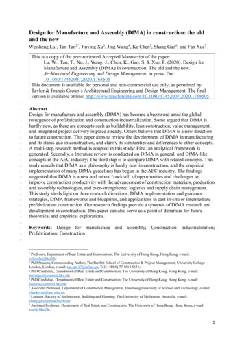
63 DESIGN METHODOLOGYFigure 2: Ratchet Drive Kitobstruction between the part and its mount point, make sure the liftingsystem can make the necessary movements.Managing heavy parts is not just a productivity issue. Heavy equipmentlifted high above people’s heads is a safety hazard, as is repetitive strain.This all is in addition to property damage.3.2.2FastenersTry to standardize on a small number of fasteners and other small,standard hardware. A worker with thirty two different fasteners kitted,must select the correct one for each attachment. They take more timeand/or they make more mistakes. Reducing the quantity of fastener types,simplifies warehousing and kitting.If power tools are being used to install fasteners, we9 do not want tochange the bit or reset the torque.Each and every hex socket cap screw requires a different sized key.10This must be searched for. The set of hex keys must be kept complete. Ifyou specify Phillips, Torx, or Robertson sockets, the assembler will spendless time searching for tools, or using the wrong tool. The ratchet drive kitin Figure 2 belongs to the author. There ought to be more slotted and9Manufacturing is not “them”. You and manufacturing are part of a team.Hex socket flat and button head cap screws smaller than M5 or #10 have tiny socketsthat strip easily. Stripped flat head screws in particular are difficult to remove and replace.Do not specify them.10
3.2 Assembly7Figure 3: Please don’tRobertson drives in it. Otherwise, we see four Phillips drives and sevenTorx drives, one of which is on the extender. There is a total of seventeenhex drives, in both English and metric sizes.3.2.3CablesCables are the responsibility of electronics. They connect intimately withthe mechanics, so mechanical and electrical designers must work as a team.Cabling strategy number one is to not have cables. DFMA manualsrecommend minimizing flexible objects. Get all your circuits onto oneprinted circuit board (PCB). There are PCB mounted connectors thatmount through panels, thus eliminating the need for additional fasteners,and cables connecting between the PCB and panel. If you have a secondPCB, mount it to the first PCB directly through board-to-board connectors.In Figure 4 the big PCB sits on the base, and is attached to the frontpanel through its connectors. Retaining nuts are not absolutely necessary.The second, smaller PCB is mounted to the big one using a board-to-boardconnector. Its LEDs extend through the cover. The cover can be designedto snap in place. It can also help retain the top PCB. There is no need forthreaded fasteners on this box.Cables are expensive to build and test. They must be routed throughyour system, and probably tied down somehow. Cable ties, like fasteners,must be documented, ordered, purchased, stored, kitted and installed.Connectors should be inserted through the inside face of a panel, as
83 DESIGN METHODOLOGYFigure 4: Box Assembly, No CablesCable assemblyFigure 5: Box With Connectors
3.2 Assembly9shown to the right on Figure 5. The two connectors and their wires are asub-assembly that can be built and tested outside the box. Manufacturinghas the option of subcontracting the cable assembly to an outside vendorwho specializes in this. The cable is built in parallel with the chassis, so itis not part of your assembly schedule critical path. Your service people havethe option of replacing the cable, rather than repairing the wires in situ.If the connector is installed through the front, as shown on the left inFigure 5, the wiring will have to be done in place. This is less flexible formanufacturing.Unfortunately, front mounted connectors look better. If looks matter,you may have to live with the inconvenience of a front mounted connector.Sometimes, you can treat the panel as part of the cable!Consider designating an ugly panel in your otherwise stylish product.Install your ugly external components on the ugly panel. Methodicallyfollow all the DFMA rules on the ugly panel, including the rear mountingof connectors. If your rear, ugly panel connector is small enough to fitthrough the front hole and the front connector threaded ring, you have aremovable cable assembly, with all the advantages noted above.A handy point is not shown on Figure 5. Connectors with screw-on nuts,as shown, usually are designed to be inserted into “D” shaped holes. Thisconstrains the connector from rotating. All the assembler needs to do iswrench the nut. This is good DFMA practice.Look for pinch points when hardware is installed on top of cables. Thesecan be difficult to assemble, and they can be dangerous.[15].3.2.4Poka YokeDesign your parts so that there is obviously only one way to install them.This prevents mistakes. It minimizes time examining drawings, and phonecalls to the design office. Make things obviously asymmetric as in Figure 6A. Add orienting features. This can be a flat on a diameter as in
103 DESIGN METHODOLOGYA.B.Figure 6: Poka YokeFigure 6B. On a pair of castings, it probably costs nothing to addorienting arrows. If you have a rectangular hole pattern or a pitch circle, move one holeout of the pattern, also shown in Figure 6B.3.3FabricationNote how we design for assembly, before we design for fabrication. Whenyou are building your widget, obviously, you do fabrication first. When youare designing, you solve all the requirements, you work out the assemblyprocess, then you design the parts and work out fabrication.Rule #1: Talk to your fabricators. They are the experts on how yourfabrication generates cost.Any parts you design must be fabricated. In theory, you prepare adrawing of the part, and manufacturing figures out how to make it. Inreality, the designer selects a fabrication process,11 uses its advantages, andcopes with its limitations. As a designer, you must understand fabricationprocesses. These are described in quite a bit of detail in Product Design forManufacture and Assembly[2].The following list is nowhere near complete. It provides a generalunderstanding, and it shows off the strategic thinking you must do to selectprocesses.11In over thirty years, the author cannot recall not knowing how a significant part wouldbe fabricated.
3.3 Fabrication3.3.111MachiningTips on Designing Cost Effective Machined Parts, by Joe Osborn[5] is anexcellent reference on dealing with machine shops.Machining ranges from accurate to extremely accurate. Machiningwastes material, especially with large, cut-from-billet parts. Part by part,machining is expensive. There is minimal tooling required to do it, somachining is an economical way to produce single parts. If accurate featuresare required, consider designing your widget around one accurate part. Allthe other pieces in your design can be fabricated from cheaper processes.Generally, if you use any process other than machining, you need towork around loose tolerances. In any sort of production, this is worthwhile.Corners of machined pockets must be rounded. A larger corner radiusallows for a larger, faster cutter. A small radius means a small cutter thatcannot withstand the side loads of heavy cutting. It may take several passesto cut a deep pocket. Through holes should be rounded too, although thereare ways to fabricate sharp, through corners. Study your part and count thenumber of setups on the mill or lathe. Each setup is expensive. Orient yourmachining radii to not force extra setups. Almost all machined parts todayare fabricated with CNC, so tool changes are done automatically, quicklyand cheaply. Machining easily produces orthogonal parts. Non-orthogonalangles require tricky setups, and/or very careful design and documentation.The material cost and machining time of a housing machined from billetvaries with the cube of its size. Small housings can be very cheap. Largehousings probably should be fabricated from pieces, from sheet metal, orcast.Beware! Machining allows bad drawings, since the tolerances required tomake your part work are well within the process’ capability, even if thedrafter did not call them up. If you have been machining all your parts andyou have started using other processes, your drafting may have toimprove.1212If your machinists figure out how your parts assemble, they may ignore your tolerancesand make your parts assemble. On a one-off assembly, this is good. When your designmoves to production, the parts may be split up between shops. Now your as-built designdoes not work!
123 DESIGN METHODOLOGYFinal machined partInaccessibleFaceMaterialCuttingToolsJaws of ChuckFigure 7: Part In LatheIn Figure 7, the part shown can be fabricated in one set-up on a lathe.The front and side features can be fabricated by the cutting tools, shown.The part can be cut off by the tool shown. Any other features on theinaccessible face require the part to be re-chucked in an extra process, atextra cost. Material is often fed through the rear of a lathe chuck. The partis fabricated and then cut off. The material is then automatically fed, andthe next part fabricated. According to Joe Osborn[5], round parts often areCNC machined by vertical mills. The rear face still is not accessiblewithout the extra set-up. When you design round parts, try to ensure thatall your features can be machined from one side.The assemblies in Figure 8 show a number of design issues. Bothassemblies hold the same printed circuit board, contained in a machinedbox. The box on the left requires at least four set-ups on a vertical mill.The first set-up machines out the insides. The second and third set-ups dothe holes on the sides. The fourth set-up drills and countersinks holes onthe bottom. The box on the right requires one set-up only. The tapped
3.3 Fabrication13Figure 8: Machined Assemblies
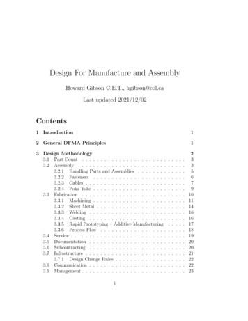
143 DESIGN METHODOLOGYFigure 9: Sheet Metal Boxholes and access to the connectors all are machined from the top.13 On theright, the pan head screws through the cover, do not require countersinks.The covers are flat, and they can be fabricated more cheaply by punchingfrom sheet metal. The countersinks on the left would be a rapid, automatictool change on a CNC mill, but they are an extra process in a sheet metalshop. The bottom screws and the hexagonal standoffs on the left hand vieware parts that must be must be documented, ordered, purchased, stored,kitted and installed. The extra features on the right are done as part of theCNC machining process, so the cost is minimal.3.3.2Sheet MetalThin, flat panels are cut using punches, water-jets or lasers. Often, the flatpanel is bent into some 3D shape as with Figure 9. Holes with sharpcorners are easily punched. Pockets must be machined, in an extra process,at extra cost. Countersunk or centre bored holes are an extra process, atextra cost. The panel can be cut out accurately. Sheet metal bending ismuch less accurate than punching or machining. You must talk to yourfabricator and ensure you understand their tolerances. If the bends are not13If a batch of these boxes are to be machined, the machinist may start from a largethick piece of material, and CNC machine nine or twelve pieces on a thick base. Havingdone this, they flip the material over and fly-cut the bottom material, releasing everything.With the assembly on the right, they completely fabricate nine or twelve pieces in twoset-ups.
3.3 Fabrication15OperationPunchingPunch feature to punch featureFormed bendsHole to edge“Standard” sheet metal tolerancesPunched holes1Hole to bendBend to bendTolerancerepeatable to .004”.005”1/2 .010” .060” .003” .015” .020”Table 1: Sheet Metal Tolerances.specified and fabricated properly, they crack.14 Make sure you specifyproper bend radii. Make sure the fabricator follows your drawings. Sheetmetal parts can be assembled in the shop by riveting or welding to createmore elaborate 3D shapes.Table 1 shows tolerances from a precision sheet metal shop.[13]If a large number of smaller sheet metal parts are required, thefabricator may build a progressive die. The material is provided as a roll ofsheet, it is fed into the die, and punched and bent, at a very high rate. Ifyou need lots of parts, make a point of understanding progressive dies.Sheet metal allows the fabrication of large, hollow, covered structures,with minimal waste of material. A carefully designed sheet metal box canbe extremely strong and rigid. Attachment points should be located closeto gussets and walls.You can specify accurate hole patterns, but you cannot locate themaccurately from bends. Read up on composite positional tolerances in yourGD&T text.[7] Make sure the composite tolerance works in your design. Itis possible to machine an accurate hole pattern, after bending, as an extraprocess, at extra cost.If you are making lots of components, investigate the packing of your flat14For any given material, there is a recommended minimum bend radius. You need tolook this up. Optimal materials for machining often are quite different from optical material for sheet metal fabrication. For example, the usual grade of aluminium for machiningis 6061-T6. For a 14 gauge panel (.064”), the bend radius is .096”. For aluminium 5052H32, the radius is .064.[6] Aluminium 5052-H32 is popular with sheet metal fabricators.
163 DESIGN METHODOLOGYpunch-outs on the metal sheet. If you design your components to packtightly, you reduce your scrap rate. 153.3.3WeldingYou can weld sheet metal. You can burn, water-jet or laser cut metal platesand weld them. You can weld structural sections like tubes, angles, I beamsand wide flange beams into a space frame.Welding is not an accurate process. You need to talk to your welder andensure you specify fabricate-able tolerances on your drawings. If you needaccurate tolerances, you need to machine your weldment, which is an extraprocess, at extra cost.Make sure the welding equipment fits into the space where you wantyour weld.Many commercial metals either are heat treated or work hardened.When you weld them, they become annealed. Stress relief and heat treatingeach are an extra process, at extra cost. These processes are not necessarilyfeasible. If the material is tricky to weld, it must be fabricated by a bettertrained, more expensive worker. Know your metallurgy.If your part is a safety critical structure, you may have to worry aboutworkmanship, quality standards, and leaving a paper trail.Welding allows all sorts of elaborate non-orthogonal structures at lowcost. If these are carefully designed, they can be extremely strong and rigid.3.3.4CastingCasting requires expensive tooling. This must be amortized over yourproduction run. Design changes require modifications to tooling, or newtooling. Casting patterns can be produced by rapid prototyping, makingone-off prototypes feasible.Compared to permanent moulding and die-casting, sand and investment153D CAD software like SolidWorks, allows you to design bent sheet metal parts, andto flatten them out to see the as-punched pattern. Take advantage of this.
3.3 Fabrication17castings use cheaper tools, making them suitable for shorter productionruns. The latter two processes can cast high melting temperature materialssuch as steel. Casting dies usually are made of steel, restricting the castmaterial to low temperature metals such as aluminium and zinc, plastic, orinvestment casting wax. Try to make the dies two-piece, and make sureyour part can be ejected from them.Once you have paid for tooling, castings are cheap. Castings can be verycomplex with little impact on cost, at least once the tooling is paid for. Acast or moulded housing can be styled with all sorts of weird, cool lookingnon-orthogonal shapes.Castings can be machined to provide accurate features and small holes,but this is an extra process, at extra cost. Try to make your design workwith the as-cast features. For example, probably, you cannot cast clearanceholes for M4 screws. Maybe you can cast holes for M8 screws!Castings and mouldings can be made from anything that can be meltedinto a liquid, including thermoplastics. Thermo-setting plastics and fibrereinforced plastics also are fabricated with moulds, and the commentsabove, apply.When you do castings, you should do aggressive DFA,16 reducing thepart count, taking advantage of the casting process, and looking for anoptimal layout for assembly.3.3.5Rapid Prototyping – Additive ManufacturingRapid prototyping, RP, is a process in which a part is constructed in somesort of 3D raster form, from a computer 3D model. The material normallyis some form of plastic. The resulting part(s) can be used for designvisualization, as functional parts, or as casting patterns. There now are RPmachines that produce metal parts.The popular technology seems to be Fused Deposition Modelling, orFDM. A nozzle is mounted on a precision XYZ translation state, andmolten thermo-plastic is squirted out into the final 3D form. The authorhas encountered FDM machines of varying quality. Any FDM part has a16Design For Assembly
183 DESIGN METHODOLOGYbasket weave finish. Maybe you can sand down external faces that must besmooth! The higher quality machines have smaller, more precise nozzles.Other RP processes can do very smooth surfaces and full colour parts, butthe plastic may not be functional for you.The part must be retained in place on a platter as it is created. This willlimit your design capabilities on the cheaper machines. A more expensivemachine the author has encountered has an additional nozzle that creates asupport structure out of plastic with a very low melting temperature. Thisis dissolved away once the rapid prototyping is complete, and the supportplastic disposed of. I believe it went down a drain somewhere, which maynot be acceptable to you.In spite of being called “Rapid Prototyping”, the processes are very slow,and not suitable for mass production.The fancy machine the author encountered used a platter assemblywhich was consumed in the RP process. Will these be available when themanufacturer stops supporting the machine? You want to know howstandard the coils of plastic raw material are, otherwise, these maydisappear along with the manufacturer.17 It would be nice if somebodymade a device that recycled your plastic into raw FDM material.Consider not buying the RP machine. There are Rapid Prototypingvendors out there, who can do multiple processes and who keep theirtechnology up to date. They can run whichever process exactly suits yourrequirement. Is it worth buying an expensive machine that you use onlyonce or twice a month.If you are desiging a casting or moulding, consider getting your foundr
Design For Manufacture and Assembly.[1] 1.Simplify the design and reduce the number of parts. 2.Standardize and use common parts and materials. 3.Design for ease of fabrication.1 4.Design within process capabilities and avoid unneeded surface nish requirements. 5.Mistake-proof product design and assembly (poka-yoke)