Transcription
DataMan 150 SeriesQuick Reference Guide2022 August 04Revision: 6.3.2.4
PrecautionsTo reduce the risk of injury or equipment damage, observe the following precautionswhen you install the Cognex product:lllllllllThis device requires the use of an LPS or NEC class 2 power supply.Do not connect or disconnect this device from the I/O module or 15-pin USBadapter cable when the I/O module or adapter cable is connected to a PC.Route cables and wires away from high-current wiring or high-voltagepower sources to reduce the risk of damage or malfunction from thefollowing causes: over-voltage, line noise, electrostatic discharge (ESD),power surges, or other irregularities in the power supply.Changes or modifications not expressly approved by the party responsiblefor regulatory compliance could void the user’s authority to operate theequipment.Ensure that the cable bend radius begins at least six inches from theconnector. Cable shielding can be degraded or cables can be damaged orwear out faster if a service loop or bend radius is tighter than 10X the cablediameter.This device should be used in accordance with the instructions in thismanual.All specifications are for reference purposes only and can change withoutnotice.This product is intended for industrial use in automated manufacturing orsimilar applications.The safety of any system incorporating this product is the responsibility ofthe assembler of the system.2
lThis product does not contain user-serviceable parts. Do not makeelectrical or mechanical modifications to product components.Unauthorized modifications can void your warranty.3
SymbolsThe following symbols indicate safety precautions and supplemental information:WARNING: This symbol indicates a hazard that could cause death, serious personal injury or electricalshock.CAUTION: This symbol indicates a hazard that could result in property damage.Note: This symbol indicates additional information about a subject.Tip: This symbol indicates suggestions and shortcuts that might not otherwise be apparent.4
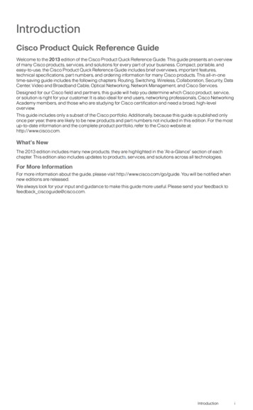
Product OverviewItemDescription1Illumination LEDs2LED aimers3-4*Mounting holes (M3 x 3.5mm)5Trigger button6Power indicator7Train status indicator8Good/bad read indicator9Communication10Error indicator5
11Tune button12Power, I/O and RS-232 connectorNote: *Use only one set of mounting holes (either 3 OR 4) for mounting.Note: The five status LEDs together also function as a peak meter using an orange light.DataMan 150 AccessoriesLENS OPTIONS, COVERS, ILLUMINATIONS AND FILTERSAccessory NameAccessory Number6.2 mm lens kitDM150-LENS-62DMA-KIT-IR-62IR 6.2 mm lens kit, 3 -position with IR LEDDMA-KIT-IR-16IR 16 mm lens kit16 mm lens with extended optics mount (requires theuse of an extended front cover and high-powered redLED)UV Light Kit for 6.2 mm lens (365nm)DM260-LENS-16Liquid Lens Module (LLM) to be used with 6.2 mm lensor 16 mm lensDMA-LLM-150-2606DMA-KIT-UV365-62Accessory Image
DM260-KIT-16LLImageMax kitClear lens cover*DM150-CVR-CLRClear lens cover, ESD safe*DM150-CVR-ESDPolarized front cover*DM260-LENS-62CVRF***Extended lens cover, un-polarized**Extended lens cover, half-polarized **Extended lens cover, fully DM260-LENS-16CVRF***C-mount adaptor, IP40DM260-CMNT-00C-mount adaptor, IP65DM260-CMNT-CVRDM150-BP470Blue bandpass filterDM150-BP635Red bandpass filterRed LED illumination*White LED illumination*Blue LED LUHigh Powered red LED illumination**DM260-LED-RED-HPNote: *Use with a 6.2 mm lens only!**Use with a 16 mm lens only!***ESD safeCABLES AND OTHER7
Accessory NameAccessory NumberDM100-EXTCBL-0005-meter extension cable*DM100-PATCH-000RS-232/USB adapter connectorUSB adapter cable with power tapUSB adapter cable with power tapDM100-USB-000DM100-USB-030DM-USBIO-00USB & Flying Leads I/O Cable, 2.0 mDM-RS232IO-00RS-232 & Flying Leads I/O Cable, 2.5 mDM100-RS232-000RS-232 adapter cable with power tapDM50-PWRIO-05Flying Leads Connection Cable, 5 mDM100-PWR-000Power supply, 6VDM100-UBRK-000Universal Mounting BracketDM100-PIVOTM-00Pivot Mounting BracketDM100-IOBOX-000DataMan Basic I/O ModuleNote: *USB/RS-232 extension connection is possible with the following limitations:1. The USB connection is shorter than 5 m.2. Serial connection is shorter than 15 m.8Accessory Image
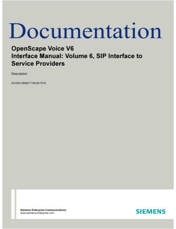
Dimensional Drawings9
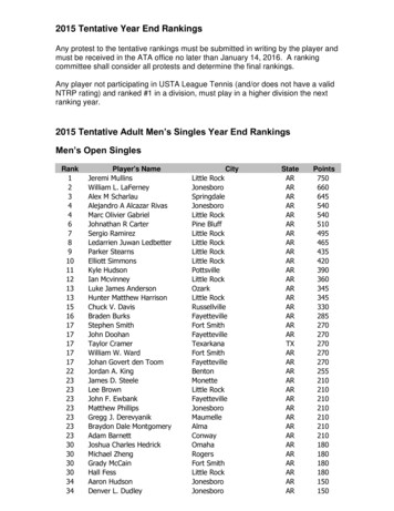
Field of View and Reading DistancesHorizontal Field of View valuesDeviceDM150DM1521234Short Range: 34 mm [1.3 Short Range: 50 mmShort Range: 77 mm [3.0 Long Range: 115 mm [4.5in][1.9 in]in]Short Range: 37 mmShort Range: 56 mmShort Range: 87 mm [3.4 Long Range: 123 mm [4.8[1.45 in][2.2 in]in]10in]in]
5DM150DM152678Long Range: 144 mmLong Range: 170 mmLong Range: 279 mmLong Range: 370 mm[5.6 in][6.7 in][10.9 in][14.5 in]Long Range: 153 mmLong Range: 181 mmLong Range: 297 mmLong Range: 394 mm[6.0 in][7.1 in][11.7 in][15.5 in]Vertical Field of View valuesDeviceDM150DM15212DM1524Short Range: 22 mmShort Range: 32 mmShort Range: 49 mmLong Range: 73 mm [2.8[0.86 in][1.25 in][1.9 in]in]Short Range: 28 mm [1.1 Short Range: 42 mmShort Range: 65 mmLong Range: 92 mm [3.6in][2.5 in]in][1.65 in]5DM1503678Long Range: 92 mm [3.6 Long Range: 108 mmLong Range: 178 mmLong Range: 236 mm [9.2in][4.25 in][7.0 in]in]Long Range: 115 mmLong Range: 135 mm [5.3 Long Range: 223 mmLong Range: 295 mm[4.5 in]in][11.6 in][8.7 in]11
Distances in mm/2D min. code6.2 mm lensLong RangeDeviceDistances in mm/1D min. code6.2 mm lensLong Range15012 MIL1506 MIL19015 MIL19010 MIL22518 MIL22510 MIL37530 MIL37515 MIL50035 MIL50020 MIL100080 MIL100035 MIL15010 MIL1505 MIL19012 MIL1906 MIL22515 MIL2256 MIL37520 MIL37510 MIL50025 MIL50015 MIL100050 MIL100030 MILDM150DM15212
Distances in mm/2D min. code6.2 mm lensShort RangeDeviceDM150DM152Distances in mm/1D min. code6.2 mm lensShort Range404 MIL402 MIL655 MIL653 MIL10510 MIL1056 MIL403 MIL402 MIL654 MIL652 MIL1057 MIL1055 MIL13
Horizontal Field of View values1234567DM70: 22 mmDM70: 43 mm DM70: 54 mm DM70: 64 mm DM70: 106DM70: 142DM70: 283[0.87 in][1.7 in]mm [4.1 in]mm [5.6 in]mm [11 in]DM72: 24 mmDM72: 45 mm DM72: 58 mm DM72: 68 mm DM72: 113DM72: 151DM72: 301[0.94 in][1.8 in]mm [5.9 in]mm [12 in][2.1 in][2.3 in][2.5 in][2.7 in]14mm [4.4 in]
Vertical Field of View values1234567DM70: 14 mmDM70: 27 mm DM70: 34 mm DM70: 41 mm DM70: 68 mm DM70: 90 mmDM70: 180[0.55 in][1.1 in]mm [7.1 in]DM72: 18 mmDM72: 34 mm DM72: 43 mm DM72: 51 mm DM72: 85 mm DM72: 113DM72: 226[0.71 in][1.3 in]mm [8.9 in][1.3 in][1.7 in][2.0 in][2.7 in][3.5 in][3.3 in]mm [4.4 in]Distances in mm/Distances in mm/2D min. code1D min. code16 mm lens16 mm lensDevice150[1.6 in]803 MIL802 MIL1505 MIL1503 MIL1906 MIL1904 MIL2257 MIL2254 MIL37512 MIL3755 MIL50015 MIL50010 MIL100025 MIL100015 MIL15
Distances in mm/Distances in mm/2D min. code1D min. codeDevice16 mm lensDM15216 mm lens802 MIL802 MIL1503 MIL1502 MIL1904 MIL1902 MIL2254 MIL2253 MIL3757 MIL3754 MIL50010 MIL5006 MIL100020 MIL100015 MIL16
Connecting the ReaderPerform the following steps:1. Connect the breakout cable (standard CAT5/5e, SF/FTP or S/FTP cable).2. Connect the reader to the PC using either the DM100-USB-000 or theDM100-RS232-000 cable. Connect a power supply: DM100-PWR-00(optional with USB, required with RS-232).For information on the pinout and wire colors, see section Connections, Optics andLighting in the DataMan 150 Reference Manual.17
MountingMounting the DataMan 150 at a slight angle (15 ) can reduce reflections andimprove reader performance.Use the set of mounting holes on the rear part to mount the DataMan reader.Connect the Breakout CableNote: You can clip unused wires short or use a tie made of non-conductivematerial to tie them back.1. Verify that the 24VDC power supply is unplugged and not receiving power.2. Connect a cable with RS-232 or USB and flying leads to the cable that isattached to the DataMan device.3. Attach the Breakout cable's 24VDC and GROUND to the correspondingterminals on the power supply.CAUTION: Never connect voltages other than 24VDC. Always18
observe the polarity shown.4. Restore power to the 24VDC power supply and turn it on if necessary.19
InstallationInstallation procedures are detailed in the DataMan 150 Reference Manual, which isinstalled with the DataMan Setup Tool. The DataMan Setup Tool is available fromthe DataMan support site: http://www.cognex.com/support/dataman.To access documentation, open the Windows Start menu, select All Programs Cognex DataMan Software vx.x.x Documentation.Note:llCables are sold separately.If a standard component is missing or damaged, immediately contactyour Cognex Authorized Service Provider (ASP) or CognexTechnical Support.CAUTION: All cable connectors are "keyed" to fit the connectors on theDataMan system; do not force the connectors or damage may occur.1. After installing the software, connect the DataMan 150 Series reader toyour PC.2. Launch the DataMan Setup Tool and click Refresh.3. Select your DataMan 150 reader from the list and click Connect.20
DataMan 150 SpecificationsSpecificationDataMan 150 Series ReaderWeight128 gOperating0ºC — 40ºC ( 32ºF — 104ºF)TemperatureStorage-10ºC — 60ºC ( 14ºF — 140ºF)TemperatureMaximum 95% (non-condensing)HumidityEnvironmental IP65Shock andVibrationIEC 60068-2-27: 1000 shocks, semi-sinusoidal, 11g, 10msIEC 60068-2-6: vibration test in each of the three main axis for 2 hours @ 10 Gs (10 to 500 Hz at100m/s2 / 15mm)LED SafetyIEC 62471: Exempt risk group, no further labeling is required.RS-232RxD, TxD according to TIA/EIA-232-FCodes1-D barcodes: Codabar, Code 39, Code 128, and Code 93,Code 25, Interleaved 2 of 5, Pharma,GS1 DataBar, Postal, Code UPC/EAN/JAN, MSI2-D barcodes: Data MatrixTM (IDMax and IDQuick: ECC 0, 50, 80, 100, 140, and 200) QR Codeand microQR Code, RSS/CS, PDF 417, MicroPDF 417, AztecCode, DotCode, MaxiCode21
Discrete I/OHS Output 0, 1operatingIMAX@ 24 VDC100 mARMAX@ 12 VDC200 Ω@ 24 VDC500 ΩLimitsInput 0 (Trigger)VIH 15 — 25 VInput 1VIL0 — 5 VITYP@ 12 VDC3.6 mA@ 24 VDC7.5 mAPower SupplylUSB powered: 500 mA (2.5 W maximum ), orRequirementslExternal power supply: 5 — 26 VDCPowerRecommended: 24 VDC (1 A maximum at 24 V, 4.5 W average at 24 V)Supplied by LPS or NEC class 2 only 2.5 W (powered over USB) 4.5 W (average, externally powered at 24 V)ConsumptionDataMan 150 Series Imager SpecificationsSpecificationDataMan 150 ImagerDataMan 152 ImagerImage Sensor1/3 inch CMOS1/3 inch CMOSImage Sensor4.51 mm x 2.88 mm (W x H), 6.0 μm4.8 mm x 3.6 mm (W x H), 3.75 μm squarePropertiessquare pixelspixelsImage Resolution752 x 4801280 x 960(pixels)22
SpecificationLens TypeDataMan 150 ImagerDataMan 152 ImagerS-mount 6.2 mm F:5 (with optional liquid lens) with IR blocking filterS-mount 16 mm F:7 (with optional liquid lens) with IR blocking filterLED WavelengthsThe following table shows LED types and the related wavelengths:LEDλ [nm]RED617RED HPIL617BLUE470WHITE6500K (Color Temperature)IR850IR HPIL850UV36523
Regulations/ConformityThe DataMan 150 Series has Regulatory Models 1AA3 and 1ABE and meets orexceeds the requirements of all applicable standards organizations for safeoperation. However, as with any electrical equipment, the best way to ensure safeoperation is to operate them according to the agency guidelines that follow. Pleaseread these guidelines carefully before using your device.Note: For the most current CE declaration and regulatory conformity information, see the Cognex supportsite: cognex.com/support.Safety and RegulatoryCognex CorporationManufacturer One Vision DriveNatick, MA 01760 USAFCC 47 CFR Part 15 Subpart B, Class AUSAThis device complies with Part 15 of the FCC Rules. Operation is subject to the following twoconditions: (1) this device may not cause harmful interference; and (2) this device must accept anyinterference received, including interference that may cause undesired operation. This equipmentgenerates, uses, and can radiate radio frequency energy and, if not installed and used inaccordance with the instruction manual, may cause harmful interference to radio communications.Operation of this equipment in a residential area is likely to cause harmful interference in whichcase the user will be required to correct the interference at their own expense.ICES-003, Class ACanadaThis Class A digital apparatus complies with Canadian ICES-003. Cet appareil numérique de laclasse A est conforme à la norme NMB-003 du Canada.24
Safety and RegulatoryEuropeAustraliaKoreaEN55022 (CISPR 22) Class AEN55024EN60950This is a class A product. In a domestic environment this product may cause radio interference inwhich case the user may be required to take immediate measures. This equipment complies withthe essential requirements of the EU Directive 2014/30/EU. Declarations are available from yourlocal representative.The CE mark on the product indicates that the system has been tested to and conforms with theprovisions noted within the 2014/30/EU Electromagnetic Compatibility Directive. For furtherinformation please contact: Cognex Corporation, One Vision Drive Natick, MA 01760 USA.Cognex Corporation shall not be liable for use of our product with equipment (i.e., power supplies,personal computers, etc.) that is not CE marked.Radiocommunications (Electromagnetic Compatibility) Standard: 2017 (EN 55032:2012)JapanKN22, KN24A급 기 기 (업 무 용 방 송 통 신 기 자 재 ): 이 기 기 는 업 무 용 (A급 ) 전 자 파 적 합 기 기 로 서 판 매자 또는 사용자는 이 점을 주의하시기 바라 며, 가정외의 지역에서 사용하는 것을 목적으 로 합니다.Certificate number:MSIP-REM-CGX-DM150MSIP-REM-CGX-DM152XVCCI V-/2013.04 Class ATÜVRegulatory Model 1AA3Regulatory Model 1ABETÜV SÜD SCC/NRTL OSHA Scheme for UL/CAN 61010-1.CB report available upon request. .TÜV SÜD, IEC/EN 61010-1.25
For European Community UsersCognex complies with Directive 2012/19/EU OF THE EUROPEAN PARLIAMENTAND OF THE COUNCIL of 4 July 2012 on waste electrical and electronic equipment(WEEE).This product has required the extraction and use of natural resources for itsproduction. It may contain hazardous substances that could impact health and theenvironment, if not properly disposed.In order to avoid the dissemination of those substances in our environment and todiminish the pressure on the natural resources, we encourage you to use theappropriate take-back systems for product disposal. Those systems will reuse orrecycle most of the materials of the product you are disposing in a sound way.The crossed out wheeled bin symbol informs you that the product should notbe disposed of along with municipal waste and invites you to use the appropriateseparate take-back systems for product disposal.If you need more information on the collection, reuse, and recycling systems, pleasecontact your local or regional waste administration.You may also contact your supplier for more information on the environmentalperformance of this product.26
中 国 大 陆 RoHS (Information for China RoHSCompliance)根 据 中 国 大 陆 《电 子 信 息 产 品 污 染 控 制 管 理 办 法 》( 也 称 为 中 国 大 陆 含的有 毒有害物质或元素的名称和含量。Table of toxic and hazardous substances/elements and their content, as required byChina’s management methods for controlling pollution by electronic informationproducts.Hazardous Substances 有 害 物 质Part Name部件名称Lead (Pb)铅Mercury(Hg)汞Cadmium(Cd)镉Hexavalent PolybrominatedChromium biphenyls (PBB)(Cr (VI))多溴联苯六价铬RegulatoryXOOOModels 1AA3,1ABEThis table is prepared in accordance with the provisions of SJ/T 11364.这 个 标 签 是 根 据 SJ / T 11364 的 规 定 准 备 的 。OPolybrominateddiphenyl ethers(PBDE)多溴二苯醚OO: Indicates that said hazardous substance contained in all of the homogeneous materials for this part is below thelimit requirement of GB / T26572 - 2011.表 示 本 部 件 所 有 均 质 材 料 中 含 有 的 有 害 物 质 低 于 GB / T26572 - 2011 的 限 量 要 求 。X: Indicates that said hazardous substance contained in at least one of the homogeneous materials used for thispart is above the limit requirement of GB / T26572 - 2011.表 示 用 于 本 部 件 的 至 少 一 种 均 质 材 料 中 所 含 的 危 害 物 质 超 过 GB / T26572 - 2011 的 限 制 要 求 。27
Copyright 2021Cognex Corporation. All Rights Reserved.
11 Tunebutton 12 Power,I/OandRS-232connector ounting. Note .