Transcription
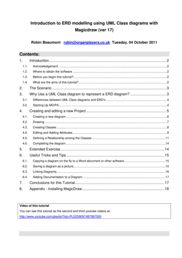
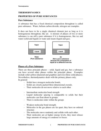
pure::variants Connectorfor MagicDraw Manualpure-systems GmbHVersion 5.0.11.685 for pure::variants 5.0Copyright 2003-2022 pure-systems GmbH2022Table of Contents1. Introduction .1.1. What is pure::variants Connector for MagicDraw? .1.2. Software Requirements .1.3. Installation .1.4. About this manual .2. Using pure::variants Connector for MagicDraw .2.1. Starting pure::variants .2.2. Setup preferences for using Connector for MagicDraw .2.3. How pure::variants Connector for MagicDraw Works .2.4. Adding MagicDraw Projects to pure::variants Family Models .3. Known Restrictions .112223333461. Introduction1.1. What is pure::variants Connector for MagicDraw?pure::variants Connector for MagicDraw enables use of product line variability concepts in MagicDraw projects. Itallows to maintain one master project from which different project variants are created automatically by selectingfeatures from Feature Models in pure::variants. So instead of having to merge changes in slight variations of thebase UML models, the change is applied once to the master project and then all relevant variants are automaticallygenerated by pure::variants.Figure 1, “Overview of family-based software development with pure::variants” shows the four cornerstone activities of software product line development and the models used in pure::variants as the basis for these activities.When building the infrastructure for your Product Line, the problem domain is represented using hierarchicalFeature Models. The solution domain, i.e. the concrete design and implementation of the software family, is implemented as UML Family Models.The two model types used for Application Engineering, i.e. the creation of product variants, are complementaryto the models described above. The Variant Description Model (VDM), containing the selected feature set andassociated values, represents a single problem from the problem domain. The Variant Result Model describes asingle concrete solution drawn from the solution family.1
pure::variants Connector for MagicDraw ManualFigure 1. Overview of family-based software development with pure::variantspure::variants manages the knowledge captured in these models and provides tool support for co-operation betweenthe different roles within a family-based software development process: The domain analyst uses the pure::variants Feature Model editor and UML/SysML models in MagicDraw tobuild and maintain the problem domain model containing the commonalities and variabilities in the given domain. The domain designer uses UML models to describe the variable family architecture and to connect it via appropriate rules to the Feature Models. The application analyst uses a Variant Description Model to explore the problem domain and to express theproblems to be solved in terms of selected features and additional configuration information. This informationis used to derive a Variant Result Model from the UML model(s) in MagicDraw. The application developer generates a member of the solution (feature selections and variant specific MagicDraw Models) from the Variant Result Model by using the transformation engine.1.2. Software RequirementsThe following software has to be present on the user's machine in order to support the pure::variants Connectorfor MagicDraw:MagicDraw:MagicDraw 18.0 - 2021x is required. Compatibility with other Tool releases is not guaranteed.Inside MagicDraw the "Product Line Engineering" plugin as well as the "pure::variants Integration" needs to be installed.The pure::variants Connector for MagicDraw is an extension for pure::variants and is available on all supportedplatforms.1.3. InstallationPlease consult section pure::variants Connectors in the pure::variants Setup Guide for detailed information on how to install the connector (menu Help - Help Contents and then pure::variants Setup Guide - pure::variants Connectors).1.4. About this manualThe reader is expected to have basic knowledge about and experiences with pure::variants. The pure::variantsmanual is available in online help as well as in printable PDF format here.2
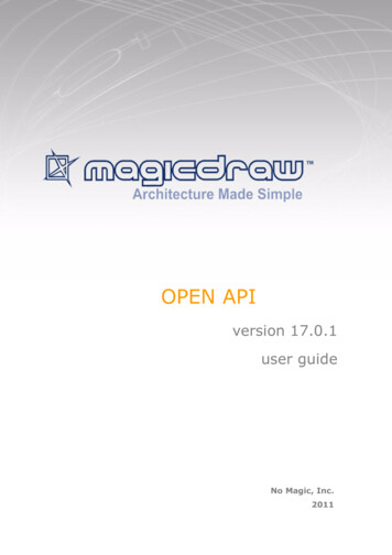
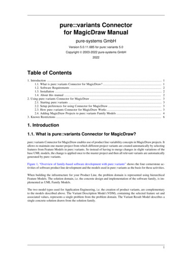
pure::variants Connector for MagicDraw Manual2. Using pure::variants Connector for MagicDraw2.1. Starting pure::variantsDepending on the installation method used either start the pure::variants-enabled Eclipse or under Windows selectthe pure::variants item from the program menu.If the Variant Management perspective is not already activated, do so by selecting it from Open Perspective- Other. in the Window menu.2.2. Setup preferences for using Connector for MagicDrawBefore the first transformation the path to the MagicDraw installation needs to be set in the connector preferences.Open the Eclipse preferences Window - Preferences and select the Connector for MagicDraw page belowVariant Management / Connector Preferences. Enter the path to your MagicDraw installation into the MagicDraw location field.Figure 2. Connector for MagicDraw Preferences2.3. How pure::variants Connector for MagicDraw WorksBefore the MagicDraw project is extended with variability information a corresponding feature model projectshould be set up in the pure::variants Connector for MagicDraw. In this pure::variants project the features to controlvariability in the MagicDraw projects are maintained. To add variability information to UML models, the conceptof UML constraints is being used. Special constraints are used to mark up optional elements and connections inan UML model such as classes, states, transition, class attributes and class members. Please see the MagicDrawdocumentation how to store variability information on the different MagicDraw model elements.The constraint language is pvSCL (pure::variants Simple Constraint Language, see pure::variants User's Guide),which provides simple and intuitive syntax for expressing feature model conditions. For instance, to make a classoptional and include it only when the feature WindSpeed is not selected in pure::variants, the corresponding pvSCLrule is simply naming the feature inside the not operator: not(WindSpeed). To create variants of the master MagicDraw, Variant Description Models (VDMs) have to be created in the pure::variants Connector for MagicDrawproject. Each VDM contains the feature selection for one project variant. The transformation of a project variantwill create an MagicDraw project variant in a specified output location. All optional elements with failing constraint have been removed from this project variant.3
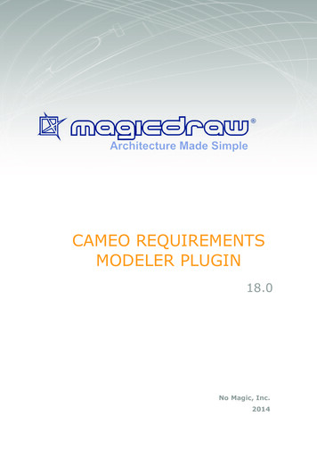
pure::variants Connector for MagicDraw Manual2.4. Adding MagicDraw Projects to pure::variants Family ModelsAdd MagicDraw project information to family models to allow the generation of variant specific MagicDrawprojects. The pure::variant Connector for MagicDraw recognizes the family model part md:project as trigger forthe transformation. Below this part must be at least one md:file element pointing to an MagicDraw project file.Figure 3. Family Model containing MagicDraw Project InformationTo influence the behavior of the transformation the md:project element can have the following two attributes: keepconstraints:If this attribute is set to true the constraints will be remain in the created project variant.Setting this to false will remove all constraints from the project during variant generation. scope:By setting the scope attribute the transformation can be limited to the specified model scopes.The family model part md:project is added to a family model by right-clicking on a component element andthen choosing New- MagicDraw Project from the context menu. This opens the wizard for a new MagicDrawproject file part as shown in Figure 4, “New MagicDraw Project wizard”. Enter the name and path to the projectfile, or navigate to an existing project file by clicking on button . to the right of field file. After finishing thewizard the part and the file element is created as shown in Figure 3, “Family Model containing MagicDraw ProjectInformation”.4
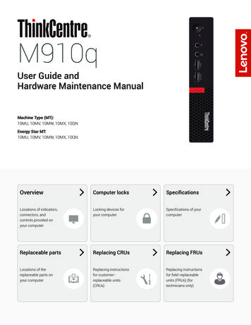
pure::variants Connector for MagicDraw ManualFigure 4. New MagicDraw Project wizardThe family model part md:project can also be added to a family model by right-clicking on a component elementand then choosing New- MagicDraw Server Project from the context menu. This opens the wizard for a newMagicDraw project file part as shown in Figure 5, “New MagicDraw Server Project wizard”. Enter a name for thenew model part. Enter the name of the existing server project in the field project, the server location in the fieldlocation and select the type in the field type. After finishing the wizard the part and the file element is created.Figure 5. New MagicDraw Server Project wizardIt is necessary to add the MagicDraw transformation to the transformation module configuration. To add thetransformation module, right-click on the configuration space, i.e. folder Products in Figure 3, “Family Modelcontaining MagicDraw Project Information”, and choose Properties from the context menu. In the Propertiesdialog switch to page Configuration Space and there to tab Transformation Configuration. Click on buttonAdd. This opens the transformation module selection dialog as shown in Figure 6, “Transformation Module Selection Dialog”.5
pure::variants Connector for MagicDraw ManualFigure 6. Transformation Module Selection DialogSelect the MagicDraw module and enter a name, then click on Finish. The transformation configuration shouldthen look as shown in Figure 7, “Transformation Configuration with MagicDraw Transformation”.Figure 7. Transformation Configuration with MagicDraw TransformationNoteBefore starting the first MagicDraw transformation it is necessary to validate the path to the MagicDrawinstallation in the preferences.3. Known Restrictions If using the integration or connector together with variant instances the instance data is not calculated correctly.6
The domain analyst uses the pure::variants Feature Model editor and UML/SysML models in MagicDraw to build and maintain the problem domain model containing the commonalities and variabilities in the given do-main. The domain designer uses UML models to describe the variable family architecture and to connect it via ap-