Transcription
CAMEO REQUIREMENTSMODELER PLUGIN18.0No Magic, Inc.2014
All material contained herein is considered proprietary information owned by No Magic, Inc. and is not to beshared, copied, or reproduced by any means. All information copyright 2014 by No Magic, Inc. All RightsReserved.
CONTENTSGETTING STARTED 5Cameo Requirements Modeler Plugin 5Compatibility 5Installing Cameo Requirements Modeler Plugin 6Requirement Concepts 6Processes and Frameworks 8Process Description 8Templates 8WORKING WITH REQUIREMENTS10Creating Requirements 10Requirement Diagram 10Requirement Table 13Relating Requirements 16Numbering Requirements 18Editing Requirement Descriptions21Rich text formatting 21Inserting images 23Inserting hyperlinks 23Glossary 24Customizing Requirement Properties 25Generating Requirement Reports 26Importing RequirementsImporting ReqIF Files2929Changing requirements importing options 31Updating requirements 31Applying automated post-processing scripts after ReqIF file import 33Managing obsolete requirement elements 33Importing from .CVS and MS Excel Files 34Importing data using CSV Import Plugin 34Importing data using Excel Import Plugin 35Exporting Requirements 36Changing Requirements Exporting Options 37Applying automated pre-processing scripts before ReqIF file export 37Interchanging of Requirements Using Cameo DataHub 38Integrating Requirements into Models 39Business Architecture 39Software Architecture 39System Architecture 39User Interface Modeling 39Analyzing Requirements 41Coverage Analysis 42Change Impact Analysis 42Analyzing dependencies in Dependency MatrixAnalyzing dependencies in Relation Map 44Tracing Requirements 4542Traceability relations in Specification window 46Traceability relations in Properties panel 48Representing traceability on Notes 50Tracing relations using Go To command 50Validation351Copyright 2011-2014 No Magic, Inc.
CONTENTSMetrics 534Copyright 2011-2014 No Magic, Inc.
G ETTIN G STA RTE DCameo Requirements Modeler PluginCameo Requirements Modeler Plugin provides full support for model-based requirements engineering. Theplugin implements the requirements part of the OMG SysML standard and provides a means to import andmanage requirements in the model. Requirements Interchange Format (ReqIF) makes the plugin open forrequirements interchange among different requirements management tools.Model-based requirements engineering brings the value of: Easy identification of the scope and potential consequence of any change. Single and consistent data source: requirements, processes, and design. Increased quality of requirements due to the automatic validation and better visibility. Saved time and resources as you are working in the same environment where your modelsare. Improved team communication with a simple and standard notation, clear diagrams, and aweb-based report.With this plugin you can: Import and export requirements in a ReqIF file from/to other requirements management tools,such as IBM DOORS 9.4, 9.5, and 9.6, IBM DOORS Next Generation, PTC Integrity, PolarionREQUIREMENTS, Siemens Teamcenter, and Dassault Systemes Reqtify. ReqIF – industrystandard, dedicated to information exchange between Requirements Management tools. Thestandard is managed by the Object Management Group and supported by major tool vendors. Trace from requirements to other model elements of business, software, or systemsarchitecture and align requirements with your model. Analyze the impact of a change. Track metrics. Capture requirements in dedicated diagrams, matrices, and tables. Document requirements. Extend the plugin by creating new requirement types and customizing the plugin’s functionality.Plugin is dedicated for business analysts and architects, software engineers, enterprise architects, systemsengineers, and other users, who work with requirements.CompatibilityThe Cameo Requirements Modeler Plugin is compatible with the following MagicDraw editions: Enterprise Professional Standard Architect5Copyright 2011-2014 No Magic, Inc.
GETTING STARTEDInstalling Cameo Requirements Modeler PluginInstalling Cameo Requirements Modeler PluginThere are several ways to install the Cameo Requirements Modeler plugin. Choose one of the following: Download and install the plugin directly via the Resource/Plugin Manager dialog in theMagicDraw program. Download the Cameo Requirements Modeler Plugin version number .zip file and theninstall the plugin via the Resource/Plugin Manager dialog. Install the plugin manually, in case the direct downloading and installing via the Resource/Plugin Manager dialog is not available.To download and install the CRM plugin via the Resource/Plugin Manager dialog1. From the MagicDraw main menu, select Help Resource/Plugin Manager. The Resource/Plugin Manager dialog opens and prompt you to check for the latest product updates andresources. Click Check for Updates Check.Specify HTTP Proxy Settings for the connection to start MagicDrawUML updates and resources.2. Select the check box near the Cameo Requirements Modeler Plugin and click Download/Install.3. Restart MagicDraw.To install the CRM plugin from the downloaded .zip file via the Resource/Plugin Manager dialog1. From the MagicDraw main menu, select Help Resource/Plugin Manager.2. Click the Import button to specify the Cameo Requirements Modeler Plugin version num-ber .zip file location. The plugin is extracted and installed automatically.3. Restart MagicDraw.To install the Requirements plugin manuallyQuit MagicDraw before installing the plugin.1. Download the Cameo Requirements Modeler Plugin version number .zip file.2. Extract the downloaded file to the same directory wherein MagicDraw is installed.If your operating system is other than Windows, use the commandline prompt to go to the MagicDraw UML folder and extract theCameo Requirements Modeler Plugin version number .zip filethere.3. Start MagicDraw. The Cameo Requirements Modeler Plugin is now applied to MagicDraw.Requirement ConceptsBusiness RequirementA Business Requirement is a requirement that specifies characteristics of the business processthat must be satisfied by the system.6Copyright 2011-2014 No Magic, Inc.
GETTING STARTEDRequirement ConceptsDesign ConstraintA Design Constraint is a requirement that specifies a constraint on the implementation of asystem or on a part of it.Extended RequirementAn Extended Requirement is a standard Requirement subtype, which adds some properties to arequirement element. These properties such as a source, risk, and verify method are importantfor the requirement management. Specific projects should add their own properties. All theseproperties are now available in the standard Requirement Specification window andRequirements Table. If any of these property values is specified, a requirement is automaticallyconverted to ExtendedRequirement.Functional RequirementA Functional Requirement is a requirement that specifies a behavior that a system or a part of asystem must perform.Interface RequirementAn Interface Requirement is a requirement that specifies the ports for connecting systems andparts of a system. Optionally, it may include the items that flow across the connector and/or theInterface constraints.Performance RequirementA Performance Requirement refers to a requirement that quantitatively measures the extent towhich a system or a system part satisfy a required capability or condition.Physical RequirementA Physical Requirement specifies the physical characteristics and/or physical constraints of asystem or a system part.ReqIFThe Requirement Interchange Format (ReqIF) standard is an XML based international standardadopted by Object Management Group (OMG) as a formal specification for exchangingrequirements between software tools from different vendors.RequirementA Requirement specifies a capability or a condition that must (or should) be satisfied.Requirements are used to establish a contract between the customer (or other stakeholder) andthose responsible for designing and implementing the system. A requirement may specify afunction that a system must perform or a performance condition a system must achieve. Arequirement can also appear on other diagrams to show its relationship to other modelingelements. A standard requirement includes properties to specify its unique identifier and textrequirement.When a requirement nests other requirements, all the nested requirements apply as a part of thecontainer requirement (the requirement that contains all the nested requirements).Requirement DiagramRequirements Diagrams provide modeling constructs to represent text-based requirements andrelate them to other modeling elements. These requirement modeling constructs are intended toprovide a bridge between traditional requirement management tools and other UML models.Requirements Diagrams display requirements, packages, other classifiers, test cases,rationales, and relationships.Requirement SpecificationA represented collection of requirements that are related by a user decision or needs. ARequirement Specification may represent requirements for a system, a component, or othersubjects. In a means of MagicDraw, a Requirement Specification is a package of requirements.7Copyright 2011-2014 No Magic, Inc.
GETTING STARTEDProcesses and FrameworksA Usability Requirement specifies the fitness for use of a system for its users and other actors.Requirement TableA Requirements Table represents textual requirements in a table format: each row represent arequirement and you can specify what columns could be in a table according your needs. A newtable consists of three columns by default: a requirement ID, name, and textual description.Test CaseA Test Case (Activity / StateMachine / Interaction) is a method for verifying a requirement.Usability RequirementA Usability Requirement specifies the fitness for use of a system for its users and other actors.Processes and FrameworksProcess DescriptionThe Cameo Requirement Modeler Plugin implements the requirements part of the OMG SysML standard that iswidely used in the system engineering. All concepts and modeling approaches that are used in requirementmodeling with the plugin are from the requirement part of the SysML standard which can be found at http://www.omgsysml.org/. The SysML requirement part provides clear essential means for the model-basedrequirements management independently from the system engineering domain, so it could be easily adoptedfor all other domains as software, business, and enterprise.The article “Requirements Writing in SysML Guide” which can be found at sml-guide/ presents one of a possible requirements modeling process which isadopted by No Magic, Inc. company internally for the development of all the products.TemplatesA requirements template contains predefined packages and diagrams to start creating your requirementsmodel. Usually, business, functional, or non-functional requirements are created.To create a requirement project from a template1. Do one of the following: From the File menu, select New Project. On the main toolbar, click the New Project button. Press CTRL N.In all cases, the New Project dialog opens.2. Type a project name and specify a project location.8Copyright 2011-2014 No Magic, Inc.
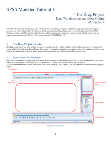
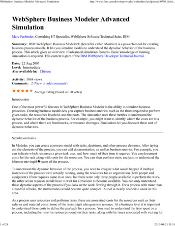
GETTING STARTEDProcesses and Frameworks3. Under the General-Purpose Modeler group, double-click the Requirements Project icon. Theproject template with predefined diagrams, samples, and resources opens.Figure 1 -- Requirement project template structure9Copyright 2011-2014 No Magic, Inc.
WO RKING WITH RE QUIRE ME NTSLearn about using the Cameo Requirements Modeler plugin in the following sections: Creating Requirements Importing Requirements Exporting Requirements Interchanging of Requirements Using Cameo DataHub Analyzing RequirementsAs with so many things in MagicDraw, there usually is more than one way to do the same thing. Just main ortypical procedure steps are described in the following sections, but feel free to use MagicDraw in the way youprefer.Creating RequirementsMagicDraw and Cameo Requirements Modeler Plugin provide modeling constructs to represent text-basedrequirements and relate them to other modeling elements. The requirements can be depicted in graphical,tabular, or tree structure format.Diagram and tables are the most popular means for requirements specification and representation in modelingtools. The following sections describe in details how to create and relate requirements in the model: Requirement Diagram Requirement Table Relating Requirements Numbering Requirements Editing Requirement Descriptions Glossary Customizing Requirement Properties Generating Requirement ReportsRequirement DiagramThe Requirement Diagram provides modeling constructs to represent text-based requirements and relate themto other modeling elements. These requirement modeling constructs are intended to provide a bridge betweentraditional requirement management tools and other models.The Requirement diagram displays requirements, packages, other classifiers, test cases, rationales, andrelationships. Possible relationships available for Requirements diagrams are containments, deriveReqt andrequirement dependencies (‘Copy’, ‘Refine’, ‘Satisfy’, ‘Trace’, and ‘Verify’). The callout notation can also beused to reflect the relationships of other models. Requirements can also be shown on other diagrams to10Copyright 2011-2014 No Magic, Inc.
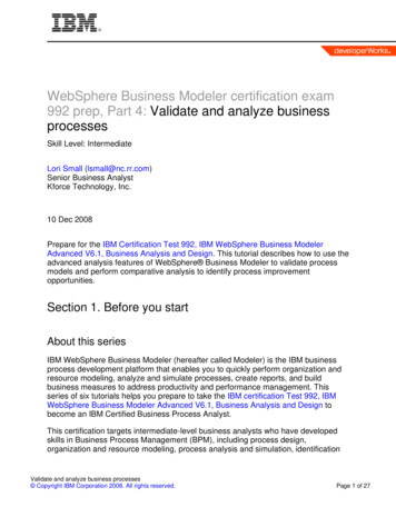
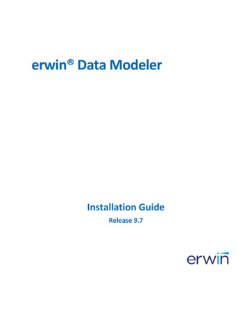
WORKING WITH REQUIREMENTSCreating Requirementsillustrate their relationships to other modeling elements.See the example of a requirements diagram in thefollowing figure.Figure 1 -- Example of Requirement DiagramYou can create requirements either directly on the Requirements Diagram or in the project Containment treeand represent it on the diagram after then.To create a requirement diagram1. In the Containment tree, select an element that can be the owner of the requirement diagram.2. Do one of the following: From the main menu, select Diagrams Create Diagram. Type “reqDia” and pressEnter. On the main toolbars, click the Create Diagram button. Type “reqDia” and pressEnter. Press Ctrl N. Type “reqDia” and press Enter. Right-click the element and from the shortcut menu select Create Diagram Requirement Diagrams Requirement Diagram.The newly created requirement diagram opens on the right side of the application window.3. Type the name of the diagram.11Copyright 2011-2014 No Magic, Inc.
WORKING WITH REQUIREMENTSCreating Requirements4. Add desired symbols on the diagram pane or drag desired elements from the project Contain-ment tree.To create requirements in the Containment tree1. In the Containment tree, right-click the package wherein you want to create a requirement.2. On the opened shortcut menu, click Select Element and then select an element you want tocreate. In this case, usually it is Requirement or Other Requirement.3. Type a requirement name.To create requirements on the Requirement diagram1. Open an existing or create a new Requirement Diagram.2. On the diagram pallet, select a desired element and drag it on the diagram pane.3. On the requirement shape, type a requirement name, ID, and description. The element is cre-ated in the same package wherein the diagram is stored.To add or edit requirement properties1. Select the desired requirement in the project Containment tree or it’s shape on the diagrampane.2. Requirement properties are added or edited in the element’s Specification Window. To open theSpecification Window, do one of the following: Double-click the selected requirement. Right-click the selected element and, on the shortcut menu, click Specification. Select a requirement and press ENTER.3. In the opened Specification Window, specify desired properties and click Close when you ardone.If a Risk, Source, or Verify Method property is specified to a requirement,the requirement is automatically converted to the Extended Requirement.For more information about using Specification Window, see “Specification Window” in MagicDrawUserManual.pdf.To change a requirement type1. Select the desired requirement in the project Containment tree or it’s shape on the diagrampane.2. Right-click the selected requirement and, on the opened shortcut menu, click Refactor Con-vert To More Specific and select a desired requirement type from the list.On the Requirement diagram, you can also represent already created requirements and relate them.To represent requirements by creating a new Requirements diagram1. In the Containment tree, right-click the requirement or package you want to draw on the dia-gram.2. From the shortcut menu, select New Diagram Requirements Diagrams RequirementDiagram.3. Type a diagram name in the Containment tree. The selected requirement is drawn on the diagram.To represent requirement on an existing Requirement diagram1. Open an existing Requirement diagram.12Copyright 2011-2014 No Magic, Inc.
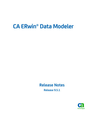
WORKING WITH REQUIREMENTSCreating Requirements2. In the Containment tree, select a desired requirement and drag it on the diagram pane.To relate requirements on the Requirement diagram1. Represent requirements on the Requirement diagram.2. Select a relation type either from the diagram pane or the smart manipulator of the selectedrequirement on the diagram pane.3. Draw the selected relation from one requirement element to other.MagicDraw provides an easy way to create a requirements diagram for sub-requirements of the selectedrequirement.To create requirements diagrams for sub-requirements1. Select a requirement in the project Containment tree or it’s symbol on the diagram pane.2. Depending on your selection do one of the following: Create a requirement diagram as usual. See the procedure “To create arequirement diagram” on page 11 If a symbol on a diagram pane is selected, click the Create diagram for sub-requirements button on the smart manipulator.A new requirements diagram for the sub-requirements is created having the same name as theselected requirement. The selected requirement is an owner of sub-requirements diagram and ismarked with the diagram sign. As an example, you can see the requirement named “ProjectManagement GUI” in the Figure 1 on page 11.Double click the owner symbol to open a diagram for subrequirements and use navigation buttons on the diagram toolbar tomove back or forward through diagrams.For more information about diagramming, see “Diagram Basics” in MagicDraw UserManual.pdf.Related proceduresRequirement TableRelating RequirementsNumbering RequirementsEditing Requirement DescriptionsRequirement TableA Requirement Table represents textual requirements in a table format: each row represent a requirement andyou can specify what columns could be in a table according your needs. With this table, you can:13Copyright 2011-2014 No Magic, Inc.
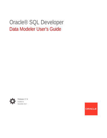
WORKING WITH REQUIREMENTSCreating Requirements Create requirements directly in the table Import existing requirements in the table Create sub-requirements directly in the table having their IDs automatically numbered Edit requirement properties Renumber requirements’ IDs Generate requirements reportsExport the table to Microsoft Excel (.xlsx), Comma Separated File (.csv) or Hyper Text Markup Language(.html) formats.Figure 2 -- Example of Requirement TableTo create a requirement table1. In the Containment tree or on the diagram pane, select an element that can be the owner of therequirement table.2. Do one of the following: From the main menu, select Diagrams Create Diagram. Type “reqT” and pressEnter. On the main toolbars, click the Create Diagram button. Type “reqT” and pressEnter. Press Ctrl N. Type “reqT” and press Enter. Right-click the element and from the shortcut menu select Create Diagram Requirement Diagrams Requirement Table.The newly created requirement table opens on the right side of the application window.3. Type a table name.4. Specify a scope for table or simply drag desired requirements from the Containment tree to thetable.To create a requirement in a requirement table1. Create a Requirement table or open an exiting one.2. On the Requirement table toolbar, click the Add New button or press INSERT. The list ofRequirement types opens.3. Click a desired requirement type. A new line above the first numbered requirement appears.4. In that empty line, type a requirement name and specify other requirement properties.14Copyright 2011-2014 No Magic, Inc.
WORKING WITH REQUIREMENTSCreating RequirementsTo represent requirements in a requirement table1. Create a Requirement table or open an exiting one.2. On the Requirement table toolbar, click the Add Existing button or press CTRL INSERT. TheSelect Requirement dialog opens.3. In the opened dialog, select requirements you want to represent in the table and click OK.Drag-and-drop the whole requirements package from theContainment tree on the empty Requirement table to represent allits content in the table.For more information about selecting elements in the Select Requirements dialog, see “Selecting an Element”in MagicDraw UserManual.pdf.To add or edit requirement properties1. Select the desired requirement in the Containment tree or the requirement’s row or it’s ID in thetable.2. Requirement properties are added or edited in the element’s Specification Window. To open theSpecification Window, do one of the following: Double-click the selected requirement in the Containment tree or the selected row inthe table. Right-click the selected element in the Containment tree, the row or requirement’sID in the table and, on the shortcut menu, click Specification. Press ENTER, if the requirement in the Containment tree or the row in the table isselected.3. In the opened Specification Window, specify desired properties and click Close when you ardone.If a Risk, Source, or Verify Method property is specified to arequirement, the requirement is automatically converted to theExtended Requirement.To export requirements to other formats1. Open a filled Requirement table.2. On the Requirement table toolbar, click the Export button. The Choose file. dialog opens.3. In the opened dialog, choose a location of the exported file, type a file name, and select a filetype the requirements will be exported. Files of .csv, .html, and .xlsx types are available toselect.4. Click Save when you are done. Requirements are exported.Please notice some formatted text (for example, tables in arequirement description) may be exported incorrectlyTo create a requirements report1. Open a filled Requirement table.2. On the Requirement table toolbar, click the Report button. The list of available report formatsopens.3. Click a desired report format. The Generate Report dialog opens.4. In the opened dialog, specify a location of the report, an image format, and other properties, ifneeded.5. Click Generate when you are done. The report are generated.For more information about generating reports and using Generate Report dialog, see “Generate OutputPane” in MagicDraw ReportWizard UserGuide.pdf15Copyright 2011-2014 No Magic, Inc.
WORKING WITH REQUIREMENTSCreating RequirementsThe Requirement table supports a wide range of editing abilities. In this table, you can: Add or remove a desired column Edit a particular element’s property directly in a cell Use rich-text formatting abilities while editing a particular cell Filter table elements by using a quick filter featureTo edit requirement tables To edit a table, use a table toolbar. To edit a cell’s value, click the selected cell and then a smallEdit button in an upper rightcorner to open a particular dialog for editing value properties.For more information about editing and managing Requirement tables, see “Generic Table” in MagicDrawUserManual.pdf.Related proceduresRequirement DiagramNumbering RequirementsEditing Requirement DescriptionsGenerating Requirement ReportsRelating RequirementsThe following table describes relations that are used in working with requirements.RelationDescriptionSatisfyIt is a dependency between a requirement and amodel element that fulfills that requirement. As withother dependencies, the arrow direction points fromthe satisfying (client) model element to the (supplier)requirement that is satisfied.16SampleCopyright 2011-2014 No Magic, Inc.
WORKING WITH REQUIREMENTSCreating RequirementsRelationDescriptionDeriveIt is a dependency between two requirements (aderived requirement and a source requirement),where the derived requirement is generated orinferred from the source requirement.CopyIt is a dependency between a supplier requirement(master) and a client requirement (slave), specifyingthat the client requirement text is a read-only copy ofthe supplier requirement text.TraceIt is a dependency between a requirement and anarbitrary model element traced by this requirement.17SampleCopyright 2011-2014 No Magic, Inc.
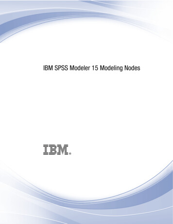
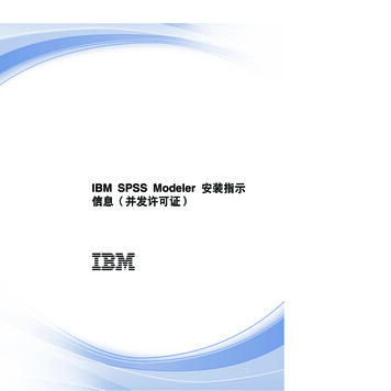
WORKING WITH REQUIREMENTSCreating RequirementsRelationDescriptionSampleVerifyIt is a dependency between a requirement and a testcase or a model element that can determine whetherthe system fulfills the requirement. As with otherdependencies, the arrow direction points from the(client) test case to the (supplier) requirement.RefineThis dependency describes how a model element ora set of elements refine a requirement. For example,a use case or activity diagram may be used to refinea text-based functional requirement. Alternatively, itmay be used to show how a text-based requirementrefines a model element. In this case, someelaborated text could be used to refine a less finegrained model element.You can create relations in the Requirement Diagram directly, see the procedure “To relate requirements on theRequirement diagram” on page 13. Also you can relate requirements and other model elements in the Derive,Refine, Satisfy, or Verify Requirement Matrix.To create a relation in Requirement Matrixes1. Create a corresponding matrix or open an existing one (see the procedure “To create a depen-dency matrix” on page 43)2. In the intersection cell do one of the following: Double click the intersection cell. The appropriate relation is created. Right-click the intersection cell and, on the shortcut menu, click the relation name.The relation is created.You can create more than one relation in the same cell if you needit.Related proceduresRequirement DiagramNumbering RequirementsEach requirement has it’s unique ID or, in terms of MagicDraw, the element number. MagicDraw allows you forusing automatic or manual elements numbering. In requirement modeling, a requirement number isunderstandable as a requirement ID. The requirement ID facilitates the search of a particular requirement andcan show the requirement’s place in the model element hierarchy.18Copyright 2011-2014 No Magic, Inc.
WORKING WITH REQUIREMENTSCreating RequirementsMagicDraw supports a wide range of number formats: you can use letters, prefixes, separator signs inrequirements IDs, and so you can constrain your specific numbering format. Also, you can choose whichnumbering scheme to use—consecutive or multi-level numbers. Use the multi-level numbering for nestedrequirements.Figure 3 -- Example of numbered requirementsRequirements can be numbered automatically or manually. To number requirements automatically, the autonumbering property should be enabled. Requirements are numbered according to the numbering scheme thatis specified for the requirement owner. If you change the numbering scheme for owning requirements, just theowner will be renumbered, all other requirements will use the old numbering scheme.To enable automatic requirement numbering1. From the main menu, select Options Project. The Project Options dialog opens.2. Select the General project options tab.3. In the Numbering properties group, set the Use Element Auto-numbering property value totrue.4. Click OK.MagicDraw supports a special generic numbering feature allowing users to create and edit numbering formatsfor element numbering.To create or edit requirement numbering format1. Open the Element Numbering dialog. Do one of the following: Right-click a selected requirement in the Containment tree or it’s shape on thediagram pane to open a shortcut menu and select the Element Numbering menucommand. Open the Specification window of the selected requirement. Click the ID propertyspecification cell and then click theEdit button.2. In the opened dialog:2.1 Select a requirement you want to number or to change the numbering format.2.2 Define a desired numbering format.19Copyright 2011-2014 No Magic, Inc.
WORKING WITH REQUIREMENTSCreating Requirements2.3 Click the Create button to create a new requirement ID or click the Details buttonto expand the dialog and click the Renumber or Renumber Recursively button tochange the existing requirement numbering format.Figure 4 -- Element Numbering dialogIn the project Containment tree, you can reorder elements just bydragging a selected element to a desired place.The numbering mechanism in details is described in the MagicDraw User Guide.For more information about the generic numbering mechanism, see “Generic Numbering Mechanism” inMagicDraw UserManual.pdf.For more information about managing elements numbering, see “Automatic Numbering” and “ManualNumbering” in MagicDraw UserManual.pdf.For more information about using the Element Numbering dialog, see “Element Numbering dialog” inMagicDraw UserManual.pdf.In MagicDraw, you can also customize your own specific numbering. The creating of the numberingcustomization is described in “Creating Numbering Customizations” in MagicDraw UML Profiling&DSLUserGuide.pdf.Related proceduresRequirement Diagram20Copyright 2011-2014 No Magic, Inc.
WORKING WITH REQUIREMENTSCreating RequirementsRequirement TableCustomizing Requirement PropertiesEditing Requirement Descriptions
Start MagicDraw. The Cameo Requirements Modeler Plugin is now applied to MagicDraw. Requirement Concepts Business Requirement A Business Requirement is a requirement that specifies characteristics of the business process that must be satisfied by the system. Specify HTTP Proxy Settings for the connection to start MagicDraw UML updates and .