Transcription
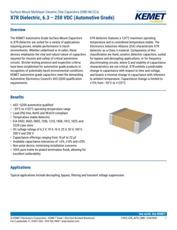
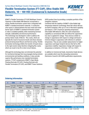
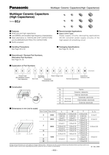
Multilayer Ceramic Capacitors(High Capacitance)Multilayer Ceramic Capacitors(High Capacitance)Series:ECJ Features Recommended Applications Small size and high capacitance Low ESR/ESL and excellent high-frequency characteristics Ideal alternative to TANTALUM CHIP CAPACITORSand ALUMINUM ELECTROLYTIC CAPACITORS RoHS compliant Class 2 (Hi-K Type)· Power supply circuitry decoupling applicationsDC-DC converter power supply circuitry of thehigh-speed LSI smoothing circuit Handling Precautions Packaging SpecificationsSee Page 48 to 53See Page 45, 46, 56 Discontinued / Revised Part Numbers,Alternative Part NumbersSee Page 54, 55 Explanation of Part Numbers123456789101112ECJ1VB0J475MProduct Code(ECJ:Multilayer CeramicChip Capacitors)PackagingRated Voltage CodeStyle CodeSize CodeTemperatureCharacteristic Code(Example)CapacitanceTolerance CodeNominal Capacitance Construction34Name1Ceramic dielectric2Internal electrode352No415TerminalelectrodeSubstrate electrodeIntermediate electrodeExternal electrode Dimensions in mm (not to scale)Size Code Size (EIA)LW00402106032T0805GL1L23L1.00 0.051.00 0.15–0.051.6 0.11.60 0.15W0.50 0.050.50 0.15–0.050.8 0.10.80 0.152.0 0.11.25 0.102.00 0.152.0 0.22.00 0.151.25 0.151.25 0.201.25 0.153.20 0.151.60 0.153.2 0.21.6 0.21206DMT0.50 0.050.50 0.15–0.050.8 0.10.80 0.150.85 0.101.25 0.101.25 0.151.25 0.200.85 0.100.85 0.101.15 0.101.6 0.20.85 0.101.15 0.10Design and specifications are each subject to change without notice. Ask factory for the current technical specifications before purchase and/or use.Should a safety concern arise regarding this product, please be sure to contact us immediately.– EC2 –L1, L20.2 0.10.3 0.20.50 0.250.6 0.302 Dec. 2008
Multilayer Ceramic Capacitors(High Capacitance) Packaging Styles and Standard Packaging QuantitiesPackagingSizeStyleThicknessCode Packaging StylesPaper tapingE(Pitch : 2 mm)Paper tapingV(Pitch : 4 mm)φ180reelFEmbossed taping(Pitch : 4 mm)YQuantity : pcs./reel0402060308051206T 0.5T 0.8T 0.85T 1.25T 0.85T 1.15T 00φ330 reel and Bulk case Type : Please contact us. Temperature Characteristics Class 2TemperatureCharacteristic CodeTemperatureCharacteristicsBX7RX5RFY5VB, XFCapacitance Change 10 % 15 % 15 % 30, –80 % 22, –82 %MeasurementTemperature Range–25 to 85 C–55 to 125 C–55 to 85 C–25 to 85 C–30 to 85 CReferenceTemperature20 C25 C25 C20 C25 CFor applicable “Temperature Characteristics”, see the lists of standard products on page 6 to 7. Rated VoltageCodeRated Voltage1HDC 50 V1EDC 25 V1CDC 16 V1ADC 10 V0JDC 6.3 V Nominal CapacitanceEx.105225106226Nominal Capacitance1,000,000 pF(1 µF)2,200,000 pF(2.2 µF)10,000,000 pF(10 µF)22,000,000 pF(22 µF) Capacitance ToleranceClass2Temperature CharacteristicsB, X7R, X5RF, Y5VCapacitance Tolerance CodeKMZCapacitance Tolerance 10 % 20 % 80, –20 %Design and specifications are each subject to change without notice. Ask factory for the current technical specifications before purchase and/or use.Should a safety concern arise regarding this product, please be sure to contact us immediately.– EC3 –02 Dec. 2008
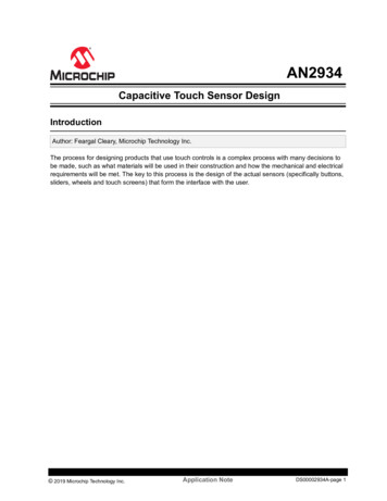
Multilayer Ceramic Capacitors(High Capacitance) Specifications and Testing MethodsItemSpecificationTest MethodOperatingTemperatureRangeTemp. Char. B, X7R : –55 to 125 CTemp. Char. B, X5R : –55 to 85 CTemp. Char. F, Y5V : –30 to 85 CDielectricWithstandingVoltageNo dielectric breakdown and/or damageTest voltage : Rated voltage 250 %Duration:1 to 5 s.Charge / Discharge current: 50 mA max.InsulationResistance(I.R.)500/C (M액) min.Note : 100/C(M액)min. for DC 10 V max.C : Nominal Cap. in µFMeasuring voltage : Rated voltageDuration : 60 5 sCharge / Discharge current: 50 mA max.CapacitanceWithin the specified toleranceDissipationFactor(tan δ)0.2 max.Please see the technical specifications for details.Measuring temperature: 20 2 CPreconditioning: The capacitors shall bekept in temperature of 150 0/–10 Cfor 1 hour and subject to standardcondition 48 4 hours before initialmeasurement.Nominal capacitance C 10 µFC 10 µFMeasuring frequency 1 kHz 10 % 120 Hz 20 %Measuring voltage 1.0 0.2 Vrms 0.5 0.2 VrmsTemperatureTemperature CharacteristicsCharacteristicsB: 10 %X7R : 15 %X5R : 15 %F: 30, –80 %Y5V : 22, –82 %Maximum capacitance change at stages 1 to 5Temp. Char.Stage 1Stage 2Stage 3(Ref. Temp.)Stage 4Stage 5B, F X7R X5R Y5V20 C 25 C 25 C 25 C–25 C –55 C –55 C –30 C20 C25 C25 C25 C85 C 125 C 85 C20 C 25 C 25 C85 C25 CSee the technical specifications fordetails such as measuring voltage.AdhesionTerminal electrodes shall be free from peeling or signs ofpeeling.Applied force : 5 NDuration : 10 sSize : 04021.00.5R0.5PC boadSample1.0Size : 0603 to 1206SampleUnit : mmAppearance: No mechanical damageCapacitance change:Temp. Char. B, X7R, X5R: within 12.5 %F, Y5V: within 30 %Bending value :1 mmBending speed : 1 mm/s20R34045 2VibrationProofAppearance : No mechanical damage.Capacitance : Within the specified tolerancetanδ : Initial standard value45 2Bending ValueBendingStrengthUnit : mmTotal amplitude : 1.5 mmVibration frequency : 10 to 55 to 10 Hzfor 1 min3 perpendicular directions for 2 hourseach, a total of 6 hours Standard condition : Temperature 15 to 35 C, Relative humidity 45 to 75 %Design and specifications are each subject to change without notice. Ask factory for the current technical specifications before purchase and/or use.Should a safety concern arise regarding this product, please be sure to contact us immediately.– EC4 –02 Dec. 2008
Multilayer Ceramic Capacitors(High Capacitance)ItemSpecificationTest MethodResistanceto SolderingHeatAppearance : No mechanical damageCapacitance change :Temp. Char. B, X7R, X5R : within 7.5 %F, Y5V : within 20 %tanδ : Initial standard valueIR : Initial standard valueWithstand voltage : No dielectric breakdown or damageSoldering bath methodPreconditioning : Heat treatment( 1)Solder temperature : 270 5 CDipping period : 3.0 0.5 sPreheat condition :Order Temp. ( C) Size 0805 max. Size 120680 to 100 120 to 180s 300 to 360s12150 to 200 120 to 180s 300 to 360sRecovery (Standard condition) : 48 4 hSolderabilityMore than 95 % of the soldered area of both terminalelectrodes shall be covered with fresh solder.Soldering bath methodSolder temperature : 230 5 CDipping period : 4 1 sSolder : H63A (JIS–Z–3282)TemperatureCycleAppearance : No mechanical damagePreconditioning : Heat treatment( 1)Step 1: Minimum operating temp. 30 3 minCapacitance change :Step 2: Room temp. 3 min max.Temp. Char. B, X7R, X5R : within 7.5 %Step 3: Maximum operating temp. 30 3 minF, Y5V : within 20 %Step 4: Room temp. 3 min max.tanδ : Initial standard valueNumber of cycles : 5 cyclesIR : Initial standard valueRecovery(Standard condition) : 48 4 hWithstand voltage : No dielectric breakdown and/or damageDamp HeatAppearance : No mechanical damage(steady state) Capacitance change :Temp. Char. B, X7R, X5R : within 20 %F, Y5V : within 30 %tanδ : Temp. Char. B, X7R, X5R : 0.25 max.F, Y5V : 0.3 max.IR : 50/C (M액) min.Note : 10/C (M액) min. for rated vol. DC 10 V max.C:Nominal cap. in µFPlease see the technical specifications for details.Preconditioning : Heat treatment( 1)Temperature : 40 2 CRelative humidity : 90 to 95 %Test period : 500 24/0 hRecovery(Standard condition) : 48 4 hDamp HeatLoadAppearance : No mechanical damageCapacitance change :Temp. Char. B, X7R, X5R : within 20 %F, Y5V : within 30 %tanδ : Temp. Char. B, X7R, X5R : 0.25 max.F, Y5V : 0.3 max.IR : 25/C (M액) min.Note : 5/C (M액) min. for rated vol. DC 10 V max.C:Nominal cap. in µFPlease see the technical specifications for details.Preconditioning : Voltage treatment( 2)Temperature : 40 2 CRelative humidity : 90 to 95 %Applied voltage : Rated voltageCharge/discharge current : 50 mA max.Test period : 500 24/0 hRecovery(Standard condition) : 48 4 hHighTemperatureLoadAppearance : no mechanical damageCapacitance change :Temp. Char. B, X7R, X5R : within 20 %F, Y5V : within 30 %tanδ : Temp. Char. B, X7R, X5R : 0.25 max.F, Y5V : 0.3 max.IR : 50/C (M액) min.Note : 10/C (M액) min. for rated vol. DC 10 V max.C:Nominal cap. in µFPlease see the technical specifications for details.Preconditioning : Voltage treatment( 2)Temperature : Maximum operation temp. 3 CApplied voltage : (1)Rated voltage 200 %(2)Rated voltage 150 %(3)Rated voltage 100 %Please see the technical specificationsfor details.Charge/discharge current : 50 mA max.Test period : 1000 48/0 hRecovery (Standard condition) : 48 4 h( 1) Heat treatment : 1 h of heat treatment at 150 0/–10 C followed by 48 4 h recovery under standard conditions.( 2) Voltage treatment : 1 h of voltage treatment under the specified temperature and voltage for testing followed by 48 4 h of recovery understandard conditions.Design and specifications are each subject to change without notice. Ask factory for the current technical specifications before purchase and/or use.Should a safety concern arise regarding this product, please be sure to contact us immediately.– EC5 –02 Dec. 2008
Multilayer Ceramic Capacitors(High Capacitance) Standard Products for EIA Size “0402”, Taped Version Class 2 Temperature Characteristic Code : B (Temperature Characteristics : X5R)Rated VoltageCapaci- Capacitancetance(µF) Tolerance1 10 %(K)2.2or 20 %(M)4.7DC 16 VDim. Temp.Char.Part No.T(mm) X5RECJ0EB1C105M 0.5 DC 10 VDim. Temp.Char.TPart No.(mm) X5RECJ0EB1A105 0.5 DC 6.3 VDim. Temp.Char.TPart No.(mm) X5RECJ0EB0J105 0.5 ECJ0EB0J225M 0.5 ECJ0EB0J475M 0.5 : Capacitance tolerance code : “ ” for “K” or “M”Dimensional tolerance of L, W, T : 0.05 mm for no mark, 0.15–0.05 mm for “ ” mark.Standard packaging quantity of Packaging Style Code “E” (T 0.5 mm) : 10,000 pcs./reel.Avoid flow soldering. Temperature Characteristic Code : F (Temperature Characteristics : F, Y5V)Rated VoltageDC 6.3 VCapaci- CapacitanceDim. Temp.Char.tancePart No.T(µF) Tolerance(mm) F Y5V1 80, –20 % (Z) ECJ0EF0J105Z 0.5 Standard packaging quantity of Packaging Style Code “E” (T 0.5 mm): 10,000 pcs./reel.Recommend soldering method : Reflow soldering. Standard Products for EIA Size “0603”, Taped Version Class 2 Temperature Characteristic Code : B (Temperature Characteristics : X5R)Rated VoltageDC 25 VCapaci- CapacitanceDim. Temp.Char.tancePart No.TTolerance(µF)(mm) X5RECJ1VB1E105 0.81 10 %(K)2.2or4.7 20 %(M)10DC 16 VDim. Temp.Char.Part No.T(mm) X5RECJ1VB1C105 0.8 ECJ1VB1C225 0.8 ECJ1VB1C475 0.8 DC 10 VDim. Temp.Char.Part No.T(mm) X5RECJ1VB1A105 0.8 ECJ1VB1A225 0.8 ECJ1VB1A475 0.8 ECJ1VB1A106M 0.8 : Capacitance tolerance code : “ ” for “K” or “M”Standard packaging quantity of Packaging Style Code “V” (T 0.8 mm): 4,000 pcs./reel.“ ” : Avoid flow soldering.“ ” : “L”, “W”, “T” Dimension Tolerance 0.15 mmDC 6.3 VDim. Temp.Char.Part No.T(mm) X5RECJ1VB0J105 0.8 ECJ1VB0J225 0.8 ECJ1VB0J475 0.8 ECJ1VB0J106M 0.8 Temperature Characteristic Code : F (Temperature Characteristics : F, Y5V)Rated VoltageDC 25 VCapaci- CapacitanceDim. Temp.Char.tancePart No.TF(µF) Tolerance(mm) 80,ECJ1VF1E105Z 0.81 2.2 –20 %(Z)DC 16 VDim. Temp.Char.TPart No.F(mm)ECJ1VF1C105Z 0.8 DC 10 VDC 6.3 VDim. Temp.Dim. Temp.Char.Char.TTPart No.Part No.(mm) F Y5V(mm) F Y5VECJ1VF1A105Z 0.8 ECJ1VF1A225Z 0.8 ECJ1VF0J225Z 0.8 Standard packaging quantity of Packaging Style Code “V” (T 0.8 mm): 4,000 pcs./reel. Standard Products for EIA Size “0805”, Taped Version Class 2 Temperature Characteristic Code : B (Temperature Characteristics : B, X5R)Rated VoltageCapaci- Capacitancetance(µF) Tolerance12.24.71022DC 25 VDim. Temp.Char.Part No.T(mm) X5RECJ2FB1E105 1.25 10 %(K) ECJ2FB1E225 1.25 orECJ2FB1E475 1.25 20 %(M)DC 16 VDim. Temp.Char.Part No.T(mm) X5RECJ2FB1C105 1.25 ECJ2FB1C225 1.25 ECJ2FB1C475 1.25 ECJ2FB1C106 1.25 DC 10 VDim.Part No.T(mm)ECJ2FB1A105 1.25ECJ2FB1A225 1.25 ECJ2FB1A475 1.25 ECJ2FB1A106 1.25 ECJ2FB1A226M 1.25 : Capacitance tolerance code : “ ” for “K” or “M”Dimensional tolerance of L, W, T : 0.1 mm for no mark, 0.15 mm for “ ” mark, 0.2 mm for “ ”mark.Standard packaging quantity of Packaging Style Code “F” (T 1.25 mm): 3,000 pcs./reel.Avoid flow soldering.Temp.Char.B X5R — — — — DC 6.3 VDim. Temp.Char.Part No.T(mm) X5RECJ2FB0J225 ECJ2FB0J475 ECJ2FB0J106 ECJ2FB0J226M1.251.25 1.25 1.25 Temperature Characteristic Code : F (Temperature Characteristics : F, Y5V)Rated VoltageDC 50 VCapaci- CapacitanceDim. Temp.Char.tancePart No.TF(µF) Tolerance(mm)ECJ2FF1H105Z 1.25 1 80,2.24.7 –20 %(Z)10DC 25 VDim. Temp.Char.Part No.TF(mm)ECJ2FF1E105Z 1.25 ECJ2FF1E225Z 1.25 DC 16 VDim.Part No.T(mm)ECJ2VF1C105Z 0.85ECJGVF1C225Z 0.85ECJGVF1C475Z 0.85DC 10 VTemp.Dim. Temp.Char.Char.Part No.TF Y5V(mm) F Y5V ECJGVF1A475Z 0.85 ECJ2FF1A106Z 1.25 Dimensional tolerance of L, W, T : L, W: 0.15 mm / T : 0.1 mm for no mark, 0.15 mm for “ ”mark.Standard packaging quantity of Packaging Style Code “V” (T 0.85 mm): 4,000 pcs./reel, “F” (T 1.25 mm): 3,000 pcs./reel.Soldering method of dimension T 1 mm: Avoid flow soldering.Design and specifications are each subject to change without notice. Ask factory for the current technical specifications before purchase and/or use.Should a safety concern arise regarding this product, please be sure to contact us immediately.– EC6 –02 Dec. 2008
Multilayer Ceramic Capacitors(High Capacitance) Standard Products for EIA Size “1206”, Taped Version Class 2 Temperature Characteristic Code : B (Temperature Characteristics : B, X7R, X5R)Rated VoltageCapaciCapacitancetanceTolerance(µF)12.2 10 %(K)or4.710 20 %(M)22DC 25 VDim.Part No.T(mm)ECJ3YB1E105 1.6ECJ3YB1E225 1.6ECJ3YB1E475 1.6ECJ3YB1E106 1.6Temp.Char.B X7R X5R ——— ———— DC 16 VDim.TPart No.(mm)ECJ3FB1C105 1.15 ECJ3YB1C225 1.6ECJ3YB1C475 1.6ECJ3YB1C106 1.6ECJ3YB1C226M 1.6Temp.Char.B X7R X5R ——— ————— DC 10 VDim. Temp.Char.TPart No.BX7R X5R(mm)ECJ3YB1A225 ECJ3YB1A475 ECJ3YB1A106 ECJ3YB1A226M1.61.61.61.6 ——— ———DC 6.3 VDim. Temp.Char.TPart No.(mm) X5R— ECJ3YB0J475 1.6 ECJDV50J106M 0.85 ECJDV50J226M 0.85 : Capacitance tolerance code : “ ” for “K” or “M”Dimensional tolerance of L, W, T: 0.2 mm for no mark, L, W: 0.15 mm / T: 0.1 mm for “ ” mark, L, W: 0.2 mm / T: 0.1 mm for “ ” mark.Standard packaging quantity of Packaging Style Code “V” (T 0.85 mm) : 4,000 pcs./reel, “F” (T 1.15 mm): 3,000 pcs./reel, “Y” (T 1.6 mm):2,000 pcs./reelAvoid flow soldering. High Temperature Series : Temperature Characteristic Code : B, X (Temperature Characteristics : B, Y7R)Rated VoltageDC 50 VDC 25 VTemp.CapaciDim.Dim. Temp.CapacitanceChar.Char.tancePart No.TTPart No.ToleranceBY7RBY7R(mm)(mm)(µF)ECJ3YX1H105 1.6 ECJ3YB1E105 1.6 1 10 %(K)2.2or4.7 20 %(M)10DC 16 VDim.TPart No.(mm)ECJ3FB1C105 1.15 ECJ3YB1C225 1.6ECJ3YX1C475 1.6ECJ3YX1C106 1.6Temp.Char.B Y7R DC 10 VDim. Temp.Char.TPart No.BY7R(mm)ECJ3YB1A225 1.6 : Capacitance tolerance code : “ ” for “K” or “M”Dimensional tolerance of L, W, T: 0.2 mm for no mark, L, W: 0.15 mm / T: 0.1 mm for “ ” mark.Standard packaging quantity of Packaging Style Code “F” (T 1.15 mm): 3,000 pcs./reel, “Y” (T 1.6 mm): 2,000 pcs./reelAvoid flow soldering. Temperature Characteristic Code : F (Temperature Characteristics : F, Y5V)Rated VoltageDC 50 VCapaciDim. Temp.CapacitanceChar.tancePart No.TToleranceF(mm)(µF) ECJ3FF1H105Z 1.151 2.2 80,4.7–20 %(Z)1022DC 25 VDim.TPart No.(mm)ECJ3FF1E105Z 1.15 ECJ3FF1E225Z 1.15 ECJ3FF1E475Z 1.15 ECJ3YF1E106Z 1.6DC 16 VDim.TPart No.F Y5V(mm) ECJ3VF1C105Z 0.85 ECJ3VF1C225Z 0.85 — ECJ3FF1C475Z 1.15 — ECJMFF1C106Z 1.15 Temp.Char.Temp.Char.F Y5V DC 10 VDim. Temp.Char.TPart No.FY5V(mm)ECJMFF1A106Z 1.15 ECJMFF1A226Z 1.15 Dimensional tolerance of L, W, T: 0.2 mm for no mark, L, W: 0.15 mm / T: 0.1 mm for “ ” mark, L, W: 0.2 mm / T: 0.1 mm for “ ”.Standard packaging quantity of Packaging Style Code “V” (T 0.85 mm): 4,000 pcs./reel, “F” (T 1.15 mm): 3,000 pcs./reel, “Y” (T 1.6 mm):2,000 pcs./reelAvoid flow soldering.Design and specifications are each subject to change without notice. Ask factory for the current technical specifications before purchase and/or use.Should a safety concern arise regarding this product, please be sure to contact us immediately.– EC7 –02 Dec. 2008
Item Specifi cation Test Method Operating Temp erature Range Temp. Char. B, X7R : -55 to 125 C Temp. Char. B, X5R : -55 to 85 C Temp. Char. F, Y5V : -30 to 85 C Dielectric Withstanding Voltage No dielectric breakdown and/or damage Test voltage : Rated voltage 250 % Duration:1 to 5 s. Charge / Discharge current: 50 mA max .