Transcription
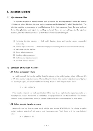
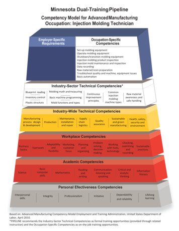
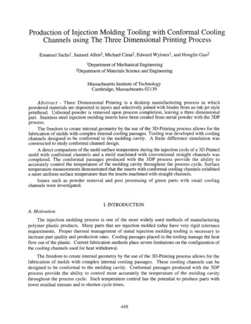
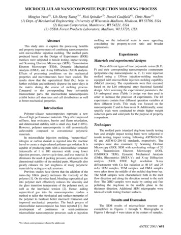
6Ceramic Injection MoldingZdravko Stanimirović and Ivanka StanimirovićIRITEL A.D.,Republic of Serbia1. IntroductionPowder injection molding (PIM), which encompasses metal injection molding (MIM) andceramic injection molding (CIM), is a net-shaping process which enables large scaleproduction of complex-shaped components for use in a diverse range of industries. Itcombines plastic injection molding techniques and performance attributes of ceramic andmetal powders. Ceramic injection molding (CIM) uses ceramic powders such as alumina,zirconia, titania, ferrite powders, etc. It was introduced in 1940's, but for the next thirty yearsit was of minor interest to ceramic industry. In 1970's and 1980's CIM provided cost-effectivefabrication method for mass production of ceramic parts for automotive industry. Todaymore than 300 companies practise PIM. Most of them practise MIM technology ( 70%).Small percentage (5%) produce metals, ceramics and carbide components and about 25%practice CIM technology. This positive tendency can be attributed to unique properties ofceramic materials. They have excellent mechanical properties and low specific weight. Also,they are suitable for applications under extreme conditions (high temperatures, corrosiveatmospheres, abrasive conditions, high loads at high temperatures). This combinationmakes them interesting for a wide variety of applications.The ceramic injection molding process consists of four basic steps: feedstock preparation,injection molding, debinding process and sintering (Fig. 1).When powder technologies arein question, the key step in production process is choosing the adequate ceramic powder.Specific surface area, particle size, size distribution, particle shape and purity of the powderinfluence properties of the feedstock. Typical particle sizes in CIM are 1-2µm, but also muchfiner particles down to submicron or nano region are being used in advanced CIM. CIMuses a feedstock of composite granulate. A high concentration of ceramic powder is mixedwith a thermoplastic binder system to form moderate viscosity feedstock - homogenouspowder-binder mix that is free of agglomerates, has optimum ceramic/binder content andstill maintains sufficient fluidity (Rak, 1999).The feedstock is molded using injection molding equipment similar to that used for polymerinjection molding. Injection molding involves concurrent heating and pressurization of thefeedstock. It requires close monitoring in order to minimize molding defects. As a result, agreen body is obtained (Fig. 2). After molding, the binder is extracted from the green body.Debinding usually takes place in two steps. Immersion is the first step. Soluble componentof the binder is removed and system of pore channels develops to allow removal of theremaining component. The second step is thermal debinding and the insoluble componentis being removed by thermal decomposition thus resulting in brown body (Fig. 2).www.intechopen.com
132Some Critical Issues for Injection MoldingFig. 1. The ceramic injection molding process.Fig. 2. CIM component: green body, brown body and sintered part, respectively.After debinding process, the sintering process takes place. Sintering parameters depend onthe type and electronic properties of the ceramic powder used and, as a result, CIMcomponents are obtained. Quality control of ceramic components in the green, brown andsintered state is commonly carried out by visual inspection and weighting. In that waysurface cracks, impurities, voids, pores, distortions, incomplete parts and skin marks can bedetected. Measuring the density of sintered components is another indispensable methodfor characterisation of CIM parts. Additional processing after sintering is optionaldepending on the type of component and specific application and in standard applicationsis seldom required.www.intechopen.com
133Ceramic Injection MoldingIn the recent past extensive international research and development activities wereperformed. Ferrite ceramics, piezoelectric ceramics and alumina were recognized as themost commonly used ceramic powders in production of wide range of CIM components forvarious applications and for that reason they are described in this chapter. Also, as aninsight in future trends of CIM technology development, advanced CIM technologies arepresented.2. Ferrite ceramics for CIMFerrites are ceramic materials based on iron-oxide. They exhibit soft magnetism andtherefore are being used in a variety of applications such as antennae, transformer cores,microwave waveguides, etc. There are three main types of ferrites: Mn-Zn ferrite, Ni-Znferrite and Mg-Zn ferrite. Ferrites have several advantages when compared to othermaterials: temperature and stability, high resistivity, wide frequency range and low losscombined with high permeability. Disadvantages are low saturation flux density and lowtensile strength. Differences between soft ferrites and other magnetic materials arepresented in Table 1 (Z. Stanimirović & I. Stanimirović, 2010).There are several techniques available to forming ferrite specimens: grinding, extrusion,pressing and injection molding. Most ferrites are commercially produced by a dry pressingprocess. The powder flows into a die cavity and upper and lower punches at about 10 tonsper surface square inch are being applied. Since the pressing is being done in verticaldirection, resulting specimen geometries are limited to simple geometric shapes. Grinding isthe most economical forming technique to produce non standard ferrite cores. It requires notooling since cores are ground from isostatically formed sintered bars. Extrusion is an idealtechnique for forming long rods and bars.ParameterInitial permeabilityrangeCurie temperaturerange [ºC]Loss factor [10-6]10kHz100kHz160kHzResistivity [ m]Saturation fluxdensity range 0104300-500800-24001000-1200Table 1. Differences between soft ferrites and other magnetic materials.However, in recent years ceramic injection molding technique (Rodrigez et al., 2003; Zlatkovet al., 2008) has been applied as an alternative forming process. Injection molded ferriteparts can be produced from very simple forms to quite complex shapes. Further processingis rarely required, but if necessary, this can be achieved using conventional tools. Partsproduced through this process can have very intricate shapes and tight tolerances. Injectionwww.intechopen.com
134Some Critical Issues for Injection Moldingmolded ferrite components have properties similar to conventionally produced parts(Skolyszewska et al., 2003; Zlatkov et al., 2010).Manganese zinc ferrite is a magnetically soft material suitable for use as magnetic cores inlow frequency range (1kHz-1MHz). For soft ferrite magnetic core production uniaxialpowder pressing technique is usually used. However, CIM as an extremely flexibletechnology enabled production of Mn-Zn ferrites with characteristics comparable withcommercial samples prepared by conventional methods. There are two reasons for CIMinvestigations of Mn-Zn ferrites: the shape complexity and the better permeability.The starting material used for the production of Mn-Zn ferrite samples was commerciallyavailable Mn-Zn ferrite powder shown in Fig. 3(a). Prior to injection molding, powder wasprocessed in a conventional manner. Mn-Zn ferrite powder in combination with binder(combination of polypropylene, microcrystalline wax and stearic acid) was used forfeedstock production. Feedstock contained 10.5% of binder (9% wax, 1% wax with lowermelting temperature, 1% of stabilizer) and 68% of Mn-Zn ceramic ferrite powder.Photograph of Mn-Zn ferrite feedstock is shown in Fig. 3(b).(a)(b)Fig. 3. Mn-Zn ferrite: powder (a) and feedstock (b).Injection molding was performed using molds in shapes required to form ring and discshaped specimens. The injection molding process was carried out in Battenfeld HM 250/60B4 machine and main injection molding parametres are given in Table 2. Debinding of greenparts after injection molding was performed in two steps: solvent and thermal debinding.Thermal debinding was performed during initial priod of sintering (150-800ºC heatingperiod) and the green ferrite samples were sintered at 1280-1320ºC/1-4h in nitrogenatmosphere.ParameterInjection temperature (ºC)Mold temperature (ºC)Injection speed (ccm/s)Injection pressure (bar)Cooling time (s)Sample ejection pressure (bar)Setup120-16030-453-20300-8001020-40Table 2. Main injection molding parameters.Photographs and dimensions of injection molded ring and disc shaped CIM Mn-Zn specimensare given in Fig. 4 and Fig. 5. The main properties of injection molded sintered Mn-Zn ferritering shaped specimens are given in Table 3 and the comparative properties of injectionmolded sintered Mn- Zn ferrite ring and disc shaped specimens are given in Table 4.www.intechopen.com
135Ceramic Injection MoldingFig. 4. Disc shaped CIM Mn-Zn ferrite samples (diameter d 16mm, thickness t 5mm).Fig. 5. Ring shaped CIM Mn-Zn ferrite samples (outer diameter do 15mm, inner diameterdi 6mm, thickness t 5mm).Tsint/t[ C/h]Grain size[μm]Relative density[% 716.350.9442.06Initial relative permeabilityLoss factor[10-6]Table 3. The main properties of injection molded sintered ring shaped Mn-Zn ferrite specimens.Initial relative permeabilityOperating frequency range [MHz]Relative loss factorMagnetic Induction [mT]Ring shaped specimens750 25%0.1-18·10-6-30·10-6390Disc shaped specimens900 25%0,01-0,55·10-6-25·10-6390Table 4. Comparative properties of injection molded sintered Mn-Zn ferrite ring and discshaped specimens.Experimental work demonstrated that Mn-Zn ferrite ceramics can be prepared usinginjection molding technique but the process is not trivial. For example, a special attentionmust be paid to initial filling of the mold. Due to uneven shrinkage rate duringwww.intechopen.com
136Some Critical Issues for Injection Moldingsolidification, creation of stresses within the body of the sample may occur resulting innucleation of voids or cracks. Also, if air pockets remain within the body of the specimenthis may lead to poor properties of the realized component.Problems may also occur during the burn out of the binder. Burn-out can be performed inair but this may cause excessive specimen shrinkage and surface layer exfoliation due tooxidative reaction. For that reason, nitrogen atmosphere was used. Sintering anddensification of the specimen during sintering is a key factor that determines magneticproperties of the sample. Highest temperature used (1320 ºC) yielded the highest sampledensities and as illustration SEM microstructure of CIM Mn-Zn ring shaped ferrite specimensintered at 1320ºC/2h is shown in Fig. 6.Fig. 6. SEM microstructure of CIM Mn-Zn ring shaped ferrite specimen sintered at 1320ºC/2h.The grain sizes of injection molded specimens are usually smaller than grain sizes ofconventionally produced Mn-Zn ferrites. Injection molding process leads to similarspecimen densities when compared to conventional methods but grain sizes are up to 50%smaller. Increase of the sintering time from 2h to 4h results in grain growth normallyexpected for Mn-Zn samples. Smaller grain sizes lead to more grain boundaries andtherefore more pinning centers resulting in lower permeability. Grain growth duringprolonged sintering cycle leads to greater densities and increased permeability but attemperatures higher than 1180ºC (Pigram & Freer, 1994) zinc volatilization occurs leading tozinc loss. For that reason, temperature of 1150ºC (Pigram & Freer, 1994) is recommended foradequate grain growth without zinc volatilization. Therefore, further work to optimize theprocessing conditions is desirable. The goal is to increase the grain size and initialpermeability of realized specimens.Experimental work on Mn-Zn ferrite has shown that ferrite ceramics can be prepared usinginjection molding technique although the process is not trivial and optimization of bothtools and processing conditions is essential. Mn-Zn sintering obtained by CIM technology issensitive process compared to the conventional pressing technology, but the obtainedresults are satisfactory. Realized Mn-Zn ferrite specimens have high green-state strength,ideal for production of delicate and complex shapes. Also, specimens exhibit satisfactorystructural integrity and magnetic properties, as well as densities similar to conventionallyproduced material.3. Piezoelectric ceramics for CIMPiezoelectric ceramics is one of the functional materials which have unique electricalproperties with broadening range of applications. Lead zirconate titanate (PbZrTiO3) andwww.intechopen.com
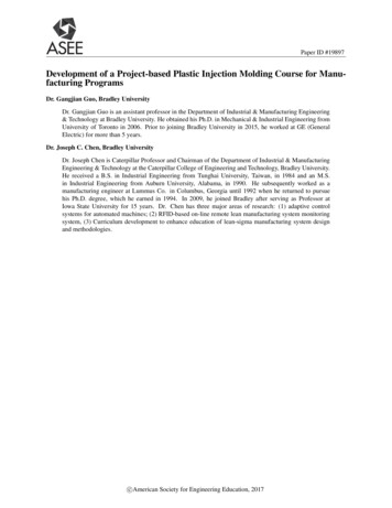
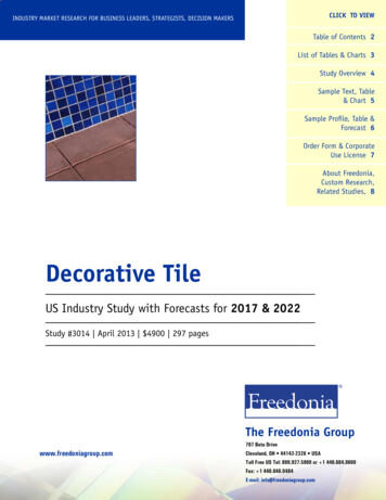
Ceramic Injection Molding137barium titanate (BaTiO3) are ceramic materials that have found widespread use – especiallylead zirconate titanate that is being widely used in sensors, transducers, microactuators,multilayer capacitors and micro-electromechanical systems (MEMS). These materials areknown for their superior piezoelectric and ferroelectric properties. When a mechanical forceis applied, piezoelectric materials generate electrical voltage. Conversely, when an electricfield is applied, these materials induce mechanical stress or strains. These effects are knownas direct piezoelectric effect and converse piezoelectric effect, respectively.Conventional powder metallurgy method is a commonly used method to producepiezoelectric materials. It starts with powder preparation. The powder is pressed to requiredshapes and size, and green shapes are processed into mechanically strong and denseceramics. Machining process is being used for achieving desired shapes of the components.Elecroding and poling are the final sterps of the process. When complex shapes are inquestion, cutting and machining of piezoelectric ceramics are time consuming. There arealso cost considerations because of the cost of the die and the waste material.The most of the published papers have dealt with fabrication and electrical properties ofpiezoelectric ceramics produced using conventional powder metallurgy method (Fig. 7).However, a little work has been carried out on the fabrication and characterisation ofpiezoelectric ceramics prepared by ceramic powder injection molding method (CIM) (Luo etal., 2006; Wang et al., 1999, Zlatkov et al., 2008). In order to synthesise piezoelectric ceramicsFig. 7. Piezoelectric ceramics production: conventional powder metallurgy method vs. CIMmethod (I. Stanimirović & Z. Stanimirović, 2010).www.intechopen.com
138Some Critical Issues for Injection Moldingusing CIM process, four basic steps should be performed: feedstock preparation, ceramicinjection molding, debinding and sintering. Components produced by CIM are expected tohave more complex shapes and more homogeneous microstructure than componentsproduced by conventional metallurgy method. Also, reduced machining and recycling useof feedstock are significantly reducing fabrication costs.In order to explore the feasibility to synthesise piezoelectric ceramics by CIM, two series oftest samples were realized (I. Stanimirović & Z. Stanimirović, 2010). Commercially availableBaTiO3 and PbZrTiO3 powders were used. Basic properties of used powders are given inTable 5. Also, photographs of BaTiO3 and PbZrTiO3 powders are given in Fig. 8, as well asthe micrograph of PbZrTiO3 powder particles Fig. 9(a).Ceramic powder:BaTiO3 PbZrTiO3Density [g/cm3]6,27,817002200Dielectric constant 33/ 010111011Isolation resistance [ m]Electromechanical coupling0,500,69coefficient k33Piezoelectric120·10-12 450·10-12coefficient d33 [C/N]Curie temperature TC [ С]118350Specific surface area [m2/g]2,62,7Table 5. Basic properties of BaTiO3 and PbZrTiO3 powders.(a)(b)Fig. 8. BaTiO3 powder (a) and PbZrTiO3 powder (b).(a)(b)Fig. 9. Scanning electron micrograph of PbZrTiO3 powder particles (a) and PbZrTiO3feedstock (b).These starting materials in combination with binder were used for feedstock production.Each feedstock contained 10.5% of binder (9% wax, 1% wax with lower meltingtemperature, 1% of stabilizer). Photograph of PbZrTiO3 feedstock is shown in Fig. 9(b).www.intechopen.com
139Ceramic Injection MoldingThe feedstock was then heated to a sufficient temperature - such that it melted and injectedinto a mold cavity where it cooled and formed desired shape. The injection molding processwas carried out in Battenfeld HM 250/60-B4 machine and the main parameters of injectionmolding corresponded to ones listed in Table 2. Dimensions of green bodies were20mm 10mm 2mm. In accordance with the binder system, debinding procedure wasperformed. A two-stage debinding technique was applied. The solvent debinding stage wasfollowed by thermal debinding stage. The main debinding parameters are given in Table 6.The slow heating rate prevented defects such as micro-cracks, slumping and blistering of theparts to be induced during debinding process.In a water bath:In chamber dryingdevice with fan:24h in a destilled water4h at 80ºC80ºC - 145ºC, rising degree [20ºC/h]145ºC - 155ºC, rising degree [0.5ºC/h]155ºC - 160ºC, rising degree [0.2ºC/h]At 160 ºC holding time 4h160ºC - 170ºC, rising degree [2-5ºC/h]170ºC - 220ºC, rising degree [10ºC/h]220ºC - 300ºC, rising degree [20ºC/h]At 300 ºC holding time 2hTable 6. Two-stage debinding procedure.After the debinding process, the debinded parts were sintered in an air atmosphere. In orderto minimize lead loss from PbZrTiO3 bodies that occur at about 800ºC, these samples weresintered in presence of a lead source. Basic information about the sintering process is givenin Table 7.Butch kilnELEKTRON 1500SaggerAlumina 98%Sagger coverAlumina 98%Bottom platesZrO2Setting andZrO2 and Pb3O4safety powderManual filling20 psc. green bodies/saggerSinteringAir atmosphereconditions21ºC -600ºC, rising degree [100ºC/h]PbZrTiO3: 600ºC-1250ºC,BaTiO3: 600ºC-1260ºC,rising degree [150ºC/h]PbZrTiO3: 1250 ºC, BaTiO3: 1260 ºC,holding time 2hCooling 1250ºC /1260ºC–21ºC: NaturalTable 7. Sintering process.Dimensions of sintered samples were 16.67mm 8.43mm 1.52mm (PbZrTiO3 samples) and16.6mm 8.42mm 1.5mm (BaTiO3 samples). After the sintering process, PbZrTiO3 sampleswww.intechopen.com
140Some Critical Issues for Injection Moldingwere silver plated using screen printing process and fired in an air atmosphere at750ºC/10min. All samples were then polarized and functional and electrical measurementswere performed (Table 8). Photographs of CIM PbZrTiO3 and BaTiO3 samples are given inFig. 10 and Fig. 11.(a)(b)Fig. 10. CIM PbZrTiO3 samples: green (a) and sintered and silver plated (b).Fig. 11. CIM BaTiO3 samples.BaTiO3PbZrTiO32000 301700 30Dielectric constant 33/ 0Loss tangent tgδmax0.020.02Electromechanical coupling0.650.50coefficient k33Piezoelectric550 50·10-12 120 50·10-12coefficient d33 [C/N]Table 8. Basic properties of BaTiO3 and PbZrTiO3 samples.In order to evaluate feasibility of producing piezoelectric ceramics by conventionalmetallurgy method and CIM, we compared results for CIM PbZrTiO3 samples obtainedfrom our study (Table 9) with those found in literature (Gu et al., 2008). Table 9 listsdielectric constants, loss tangents, electromechanical coupling coefficients and piezoelectriccoefficients for samples obtained by those two methods.The dielectric constant is a measure of charge stored on an electrode material brought to agiven voltage. It strongly depends on sintering temperature for both CIM and conventionalmetallurgy method. When conventional method is concerned, dielectric constant increaseswith sintering temperature due to the increase in PbZrTiO3 grains. For CIM samples, dielectricconstant increases with sintering temperature to 1250ºC and then decreases with sinteringtemperature because of the deceased density due to lead loss. Therefore observed difference inwww.intechopen.com
Ceramic Injection Molding141dielectric constants obtained by two methods can be attributed to microstructure developmentand change in grain size with variation of sintering temperature.CIM method Conventional powdermetallurgy method(Gu et al., 2008)1210Dielectric constant 33/ 0 1700 30Loss tangent tgδmax0.021.0Electromechanical0.500.27coupling coefficient k33120 5097Piezoelectriccoefficientd33 [10-12C/N]Table 9. Comparative properties of PbZrTiO3 samples.Electromechanical coupling coefficient and piezoelectric coefficient are slightly lower thanthose from reference, while the loss tangent is higher for samples realized using CIMmethod than for samples obtained by conventional metallurgy method. They stronglydepend on processing parameters, especially sintering temperatures, and by furtheradjustment of various processing parameters, CIM technology can provide PbZrTiO3components with application-specific properties similar to those provided by conventionallyproduced components.Obtained results have shown that piezoelectric ceramics can be successfully produced byCIM method. Sintering temperature was found to play important role in physical,mechanical and electrical properties since it affects sample density and porosity. Theobtained sample properties were comparable to those found in literature. It is important tonote that in comparison with conventional powder metallurgy, CIM samples have morehomogenous microstructure and production costs are reduced by reducing machining andrecycling use of feedstock. Further research should be focused on processing conditions andtheir influence on the properties of final sintered parts, assuring satisfactory low-costalternative for the production of piezoelectric ceramics with application specific properties.4. Alumina for CIMAluminium oxide (Al2O3) is ceramics with high mechanical hardness, high electricalresistivity and thermal conductivity. It has good strength and stiffness, good wear andcorrosion resistance, good thermal stability, low dielectric constant and loss tangent, lowthermal expansion, low weight, etc. It is suitable for technical ceramic, electronic andmedical products, etc. CIM alumina exhibits properties close to pressed and sinteredsamples (Hwang & Hsieh, 2005; Hausnerova et al., 2011; Krauss et al., 2005). The mostcommon material that is being used for feedstock preparation is Al2O3 powder with 99.7%purity (Wei et al., 2000). Properties and scanning electron micrograph of 99.7% aluminapowder are given in Table 10 and Fig. 12.Multicomponent binder commonly used in feedstock preparation is 30wt% polypropilene,65wt% paraffin wax and 5wt% stearic acid. After injection molding procedure, samples arebeing subjected to a debinding process (Table 11). After the debinding procedure, allwww.intechopen.com
142Some Critical Issues for Injection Moldingsamples should be inspected to ensure that all surfaces are free from visual defect. CIMalumina samples are then sintered in air at temperatures 1550ºC.MaterialAl2O3 99.7%Typical compositionNa2O (0.05%)SiO2 (0.05%) CaO (0.02%) Fe2O3 (0.02%)Typical properties of sintered partsParticle size, d500.4-0.6 μmTheoretical density 3.85 g/cm3Density96.7 %Purity99.7 %Specific surface area 9.0 m2/gTable 10. Properties of Al2O3 powder.Fig. 12. Scanning electron micrograph of alumina powder.Immersion:heptane, 3h at 60ºCThermal debinding:Ramping rate (ºC/min) Isothermal temperature (ºC) holding time (h)22000.322502.0545001010000.5CoolingTable 11. Typical debinding procedure for CIM alumina samples.CIM alumina is the most widely used injection molded ceramic material. CIM aluminacomponents (Fig. 13) have high surface finish quality even with extremely complexgeometries. They have high hardness end mechanical strength, high wear and corrosionstability and good electrical insulation. CIM alumina components are also dimensionallystable and able to withstand high working temperatures. Since they combine goodmechanical properties with low specific weight, CIM alumina components are being used inengineering (sensor covers, sensor tubes, micro electrodes for ultrasonic welding, etc.),textile industry (textile thread guides, wire guides, etc.), medical and dental applications(orthodontic brackets, dental implants, prosthetic replacements, etc.), watches (precisionwatch gears), metallurgy (ceramic casting cores), automotive components (valvecomponents), electrical components (microwave dielectric components), office equipment(inkjet printheads), etc. Recent research activities proved that CIM alumina has a greatpotential because nowadays it is a commonly used material in both micro-CIM and 2C-CIMtechnology – advanced CIM technologies.www.intechopen.com
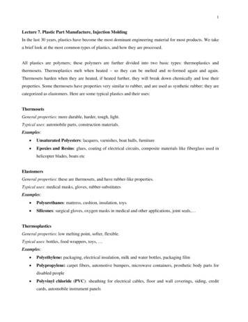
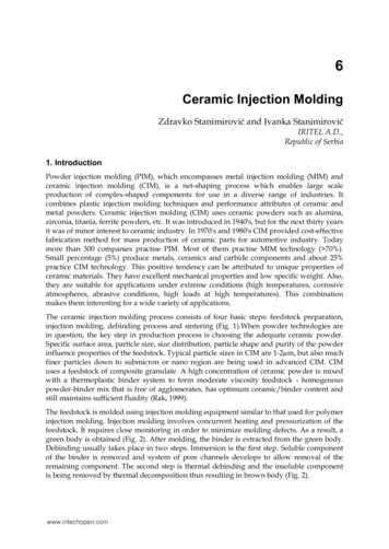
143Ceramic Injection MoldingFig. 13. CIM Al2O3 sample.5. Advanced CIM technologiesMass produced micro-parts are mainly being produced from ceramic materials which arereadily available in submicron sizes because fine ceramic powders are easier to handle incomparison with metallic materials which are often pyrophoric in submicron sizes and forthat reason difficult to handle. Micro-CIM, as an expanding technology for mass-productionof micro-parts, emerged as a combination of plastic micro-injection molding technology andceramic injection molding technology. It shares the same basic steps as the conventionalCIM-technology, but it also exhibits special characteristics due to micro-size of thecomponents (Liu et al., 2011; Piotter et al., 2003, 2010; Zauner, 2006). Micro-CIM parts can beformed using variety of ceramic materials such as ZrO2, Al2O3, Si3N4, AlN and PZT andtheir main application fields are microsystem technology, microfluidics, biosensors, MEMS,medical technology, etc. (Fig. sensorsMEMSMedicaltechnologyFig. 14. Micro-CIM applications.The increasing expansion of microsystem technology (MST) induced a great demand for theproduction of high-quality low-cost 3D micro-sized components such as micro-sensors,micro-reactors and micro-parts. The current microsystem production technologies (microcutting, laser ablation, LIGA, etc.) due to their high cost, low efficiency and limited materialsare being replaced by micro-CIM technology that, as a miniaturized variant of CIMtechnology, offers greater shape complexities, applicability to a wide range of materials andgood mechanical properties. Micromechanical components made by micro-CIM are used towww.intechopen.com
144Some Critical Issues for Injection Moldingreplace plastic parts and they especially benefit from ceramic material properties likecorrosion resistance and high-temperature performance. Microfluidics and microreactiontechnology, biomedical industry and other growing markets give excellent opportunities formicroparts. For some applications, such as reactions of highly corrosive media or hightemperature gas phase reactions, micro-CIM components are of greatest interest due to theirhardness and high chemical and thermal resistance. Also, there is a strong request forbiocompatible materials such as ceramics and reliable technologies to produce complexshaped medical components.The raw materials for micro-CIM technology are fine ceramic powders that allowproduction of micro-components with feature sizes down to 5μm. The powder has to behomogeneous and in order to obtain a fairly isotropic behavior the grain size of the sinteredpart should be at least one order of magnitude smaller than the minimum internaldimensions of the micro-part. From the aspect of surface quality, the best results can beachieved by using ceramic powders with mean particle diameter of 0.5μm or smaller. Theviscosity of the melt should be sufficiently low to fill even the smallest structural detailsdown to submicron range. For that reason, the molding tool should be heated near themelting point of the feedstock prior to injection into the tool. Because of the micro-partfragility highly precise tool movements are required. In order to control accelerationor slowing down of the injection molding process, ramps are being used. Micro injectionmolding machines use position regulated screws for that purpose. Also, micro componentsare considerably more difficult to handle from macroscopic components. They tend tostick to handling systems instead of dropping when electrostatic forces exceed gravitationforce.As an example of micro-CIM component, schematic presentation of zirconia (ZrO2) microgearwheel is shown in Fig. 15. It is a typical example of micro component for micromechanicalapplications. Micro gearwheels are demanding microstructures. Successful replication ofstructural details requires establishment of critical dimensions and determination of variousphysical properties such as densities, surface qualities, etc. However, geometry of the part isnot a key factor when performances of the component are in question. The key factor is thesurface quality of micro-CIM component. For production of ZrO2 micro gearwheels highquality mold inserts are required. Cavities have to be scaled up by the certain percentagebecause of the shrinkage and have to be micro milled employing smallest mill cutters.Minimum edge radius within the mold and cutting depth affect the tooth shape. Besidesrestrictions related to manufacturing adequate mold inserts for micro gearwheel realization,there are also restrictions of molding as well as restrictions of sintering. Beside typical limitsfor ejection molding (aspect ratio), there are limitations related to design of the gate system.Demolding is also a challenge because the ejector pins have to be arranged very accuratelydue to the lack of space. When sintering process is in question, the shrinking, temperatureand other process variables must be particularly taken into account. There are differenttemperatures in different places in the oven resulting in variable shrinking factors andtherefore different si
ceramic injection molding (CIM), is a net-shaping process which enables large scale production of complex-shaped components for use in a diverse range of industries. It combines plastic injection molding techniques and performance attributes of ceramic and metal powders. Ceramic injection mol