Transcription
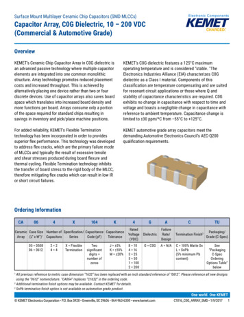
Surface Mount Multilayer Ceramic Chip Capacitors (SMD MLCCs)Capacitor Array, C0G Dielectric, 10 – 200 VDC(Commercial & Automotive Grade)OverviewKEMET’s Ceramic Chip Capacitor Array in C0G dielectric isan advanced passive technology where multiple capacitorelements are integrated into one common monolithicstructure. Array technology promotes reduced placementcosts and increased throughput. This is achieved byalternatively placing one device rather than two or fourdiscrete devices. Use of capacitor arrays also saves boardspace which translates into increased board density andmore functions per board. Arrays consume only a portionof the space required for standard chips resulting insavings in inventory and pick/place machine positions.KEMET’s C0G dielectric features a 125 C maximumoperating temperature and is considered “stable. "TheElectronics Industries Alliance (EIA) characterizes C0Gdielectric as a Class I material. Components of thisclassification are temperature compensating and are suitedfor resonant circuit applications or those where Q andstability of capacitance characteristics are required. C0Gexhibits no change in capacitance with respect to time andvoltage and boasts a negligible change in capacitance withreference to ambient temperature. Capacitance change islimited to 30 ppm/ºC from 55 C to 125 C.For added reliability, KEMET's Flexible Terminationtechnology has been incorporated in order to providessuperior flex performance. This technology was developedto address flex cracks, which are the primary failure modeof MLCCs and typically the result of excessive tensileand shear stresses produced during board flexure andthermal cycling. Flexible Termination technology inhibitsthe transfer of board stress to the rigid body of the MLCC,therefore mitigating flex cracks which can result in low IRor short circuit failures.KEMET automotive grade array capacitors meet thedemanding Automotive Electronics Council's AEC-Q200qualification requirements.Click image above for interactive 3D contentOrdering InformationCA064Open PDF in Adobe Reader for full functionalityX104KCeramic Case Size Number of Specification/ Capacitance CapacitanceSeriesCode (pF)ToleranceArray (L" x W")1 Capacitors05 050806 06122 24 4X FlexibleTerminationTwosignificantdigits number ofzerosJ 5%K 10%M signTermination Finish2Packaging/Grade (C-Spec)G C0GA N/A8 104 163 255 501 1002 200C 100% Matte SnL SnPb(5% minimum Pbcontent)See"PackagingC-SpecOrderingOptions Table"belowAll previous reference to metric case dimension "1632" has been replaced with an inch standard reference of "0612". Please reference all new designsusing the "0612" nomenclature. "CA064" replaces "C1632" in the ordering code.2Additional termination finish options may be available. Contact KEMET for details.2SnPb termination finish option is not available on automotive grade product.1One world. One KEMET KEMET Electronics Corporation P.O. Box 5928 Greenville, SC 29606 864-963-6300 www.kemet.comC1016 C0G ARRAY SMD 1/9/20171
Surface Mount Multilayer Ceramic Chip Capacitors (SMD MLCCs)Capacitor Array, C0G Dielectric, 10 – 200 VDC, (Commercial & Automotive Grade)Packaging C-Spec Ordering Options TablePackaging/GradeOrdering Code (C-Spec)Packaging TypeCommercial Grade1Bulk Bag7" Reel/Unmarked13" Reel (Embossed Plastic Tape)/UnmarkedNot Required (Blank)TU7210Automotive Grade27" Reel13" Reel/Embossed Plastic/UnmarkedAUTOAUTO7210Default packaging is "Bulk Bag". An ordering code C-Spec is not required for "Bulk Bag" packaging.The terms "Marked" and "Unmarked" pertain to laser marking option of capacitors. All packaging options labeled as "Unmarked" will containcapacitors that have not been laser marked. The option to laser mark is not available on these devices. For more information see "Capacitor Marking".2Reeling tape options (Paper or Plastic) are dependent on capacitor case size (L" x W") and thickness dimension. See "Chip Thickness/Tape & ReelPackaging Quantities" and "Tape & Reel Packaging Information".2For additional Information regarding "AUTO" C-Spec options, see "Automotive C-Spec Information".2All Automotive packaging C-Specs listed exclude the option to laser mark components. The option to laser mark is not available on these devices. Formore information see "Capacitor Marking".11Benefits 55 C to 125 C operating temperature rangeSuperior flex performance (up to 5 mm)Saves both circuit board and inventory spaceReduces placement costs and increases throughputLead (Pb)-free, RoHS and REACH compliantEIA 0508 (2-element) and 0612 (4-element) case sizesDC voltage ratings of 10 V, 16 V, 25 V, 50 V, 100 V,and 200 V Capacitance offerings ranging from 10 pF to 2,200 pFAvailable capacitance tolerances of 5%, 10%, and 20%Non-polar device, minimizing installation concerns100% pure matte tin-plated termination finish allowing forexcellent solderability SnPb termination finish option available upon request(5% Pb minimum) Commercial and Automotive (AEC–Q200) grades availableApplicationsTypical applications include those that can benefit from board area savings, cost savings and overall volumetric reductionsuch as telecommunications, computers, handheld devices and automotive. Flexible termination technology benefitsapplications subject to high levels of board flexure or temperature cycling. KEMET Electronics Corporation P.O. Box 5928 Greenville, SC 29606 864-963-6300 www.kemet.comC1016 C0G ARRAY SMD 1/9/20172
Surface Mount Multilayer Ceramic Chip Capacitors (SMD MLCCs)Capacitor Array, C0G Dielectric, 10 – 200 VDC, (Commercial & Automotive Grade)Automotive C-Spec InformationKEMET Automotive Grade products meet or exceed the requirements outlined by the Automotive Electronics Council.Details regarding test methods and conditions are referenced in document AEC–Q200, Stress Test Qualification for PassiveComponents. These products are supported by a Product Change Notification (PCN) and Production Part Approval Processwarrant (PPAP).Automotive products offered through our distribution channel have been assigned an inclusive ordering code C-Spec,“AUTO”. This C-Spec was developed in order to better serve small and medium sized companies that prefer an automotivegrade component without the requirement to submit a customer Source Controlled Drawing (SCD) or specification for reviewby a KEMET engineering specialist. This C-Spec is therefore not intended for use by KEMET’s OEM Automotive customersand are not granted the same “privileges” as other automotive C-Specs. Customer PCN approval and PPAP request levels arelimited (see details below).Product Change Notification (PCN)The KEMET Product Change Notification system is used to communicate primarily the following types of changes: Product/process changes that affect product form, fit, function, and/or reliability Changes in manufacturing site Product obsolescenceProcess/Product changeObsolescence*Days prior toimplementationKEMET assignedYes (with approval and sign off)Yes180 days MinimumAUTOYes (without approval)Yes90 days Minimum11Customer Notification due to:KEMET AutomotiveC-SpecKEMET assigned C-Specs require the submittal of a customer SCD or customer specification for review. For additional information contact KEMET.Production Part Approval Process (PPAP)The purpose of the Production Part Approval Process is: To ensure that supplier can meet the manufacturability and quality requirements for the purchased parts. To provide the evidence that all customer engineering design record and specification requirements are properlyunderstood andfulfilled by the manufacturing organization. To demonstrate that the established manufacturing process has the potential to produce the part12345KEMET assigned AUTO 11PPAP (Product Part Approval Process) LevelKEMET AutomotiveC-Spec KEMET assigned C-Specs require the submittal of a customer SCD or customer specification for review. For additional information contact KEMET. Part Number specific PPAP available Product family PPAP only KEMET Electronics Corporation P.O. Box 5928 Greenville, SC 29606 864-963-6300 www.kemet.comC1016 C0G ARRAY SMD 1/9/20173
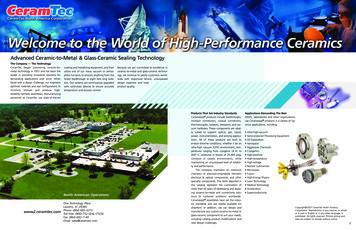
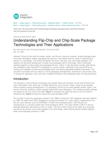
Surface Mount Multilayer Ceramic Chip Capacitors (SMD MLCCs)Capacitor Array, C0G Dielectric, 10 – 200 VDC, (Commercial & Automotive Grade)Dimensions – Millimeters (Inches)0508 (2-CAP)0612 (4-CAP)Top ViewTop ViewProfile ViewProfile ViewBWBWPLTP RefLCLWBLCLPRefTBLWPEIA SizeCodeMetric 201.30 (0.051) 0.15 (0.006)2.10 (0.083) 0.15 (0.006)0.53 (0.021) 0.08 (0.003)061216321.60 (0.063) 0.20 (0.008)3.20 (0.126) 0.20 (0.008)0.40 (0.016) 0.20 (0.008)0.30 (0.012) 0.20 (0.008) See Table 2 forThickness0.30 (0.012) 0.20 (0.008)TThicknessPPitchPReference1.00 (0.039) 0.10 (0.004)0.50 (0.020) 0.10 (0.004)0.80 (0.031) 0.10 (0.004)0.40 (0.016) 0.05 (0.002)Qualification/CertificationCommercial Grade products are subject to internal qualification. Details regarding test methods and conditions arereferenced in Table 4, Performance & Reliability.Automotive Grade products meet or exceed the requirements outlined by the Automotive Electronics Council. Detailsregarding test methods and conditions are referenced in document AEC–Q200, Stress Test Qualification for PassiveComponents. For additional information regarding the Automotive Electronics Council and AEC–Q200, please visit theirwebsite at www.aecouncil.com.Environmental ComplianceLead (Pb)-free, RoHS, and REACH compliant without exemptions (excluding SnPb termination finish option). KEMET Electronics Corporation P.O. Box 5928 Greenville, SC 29606 864-963-6300 www.kemet.comC1016 C0G ARRAY SMD 1/9/20174
Surface Mount Multilayer Ceramic Chip Capacitors (SMD MLCCs)Capacitor Array, C0G Dielectric, 10 – 200 VDC, (Commercial & Automotive Grade)Electrical isticsOperating Temperature RangeCapacitance Change with Reference to 25 C and 0 VDC Applied (TCC)Aging Rate (Maximum % Capacitance Loss/Decade Hour)Dielectric Withstanding Voltage (DWV)12Dissipation Factor (DF) Maximum Limit at 25ºC3Insulation Resistance (IR) Limit at 25 C 55 C to 125 C 30 ppm/ºC0%250% of rated voltage(5 1 seconds and charge/discharge not exceeding 50 mA)0.1%1,000 megohm microfarads or 100 GΩ(Rated voltage applied for 120 5 seconds at 25 C)DWV is the voltage a capacitor can withstand (survive) for a short period of time. It exceeds the nominal and continuous working voltage of thecapacitor.2Capacitance and dissipation factor (DF) measured under the following conditions:1 MHz 100 kHz and 1.0 Vrms 0.2 V if capacitance 1,000 pF1 kHz 50 Hz and 1.0 Vrms 0.2 V if capacitance 1,000 pF3To obtain IR limit, divide MΩ-µF value by the capacitance and compare to GΩ limit. Select the lower of the two limits.Capacitance and Dissipation Factor (DF) measured under the following conditions:Note: When measuring capacitance it is important to ensure the set voltage level is held constant. The HP4284 and Agilent E4980 have a feature knownas Automatic Level Control (ALC). The ALC feature should be switched to "ON."1Post Environmental LimitsHigh Temperature Life, Biased Humidity, Moisture ResistanceDielectricRated DCVoltageCapacitanceValueDissipation Factor(Maximum %)CapacitanceShiftC0GAllAll0.50.3% or 0.25 pFInsulationResistance10% of InitialLimit KEMET Electronics Corporation P.O. Box 5928 Greenville, SC 29606 864-963-6300 www.kemet.comC1016 C0G ARRAY SMD 1/9/20175
Surface Mount Multilayer Ceramic Chip Capacitors (SMD MLCCs)Capacitor Array, C0G Dielectric, 10 – 200 VDC, (Commercial & Automotive Grade)Table 1 – Capacitance Range/Selection Waterfall (0508 – 0612 Case Sizes)Case Size/SeriesCapacitanceCapacitance Voltage CodeCodeRated Voltage (VDC)10 pF12 pF15 pF18 pF22 pF27 pF33 pF39 pF47 pF56 pF68 pF82 pF100 pF120 pF150 pF180 pF220 pF270 pF330 pF390 pF470 pF560 pF680 pF820 pF1,000 pF1,100 pF1,200 pF1,300 pF1,500 pF1,600 pF1,800 pF2,000 pF2,200 JJJJJJJJJJC0508X (CA052X 2-Cap Case Size)C0612X (CA064X 4-Cap Case ceToleranceProduct Availability and Chip Thickness CodesSee Table 2 for Chip Thickness APAPAPAPAPAPAPAPAPAPAPAPAPARated Voltage (VDC)1016255010010Voltage Code843518Case Size/SeriesC0508X (CA052X 2-Cap Case Size)C0612X (CA064X 4-Cap Case Size)KEMET reserves the right to substitute product with an improved temperature characteristic, tighter capacitance tolerance and/or higher voltagecapability within the same form factor (configuration and dimensions).These products are protected under US Patents 7,172,985 and 7,670,981, other patents pending, and any foreign counterparts. KEMET Electronics Corporation P.O. Box 5928 Greenville, SC 29606 864-963-6300 www.kemet.comC1016 C0G ARRAY SMD 1/9/20176
Surface Mount Multilayer Ceramic Chip Capacitors (SMD MLCCs)Capacitor Array, C0G Dielectric, 10 – 200 VDC, (Commercial & Automotive Grade)Table 2A – Chip Thickness/Tape & Reel Packaging QuantitiesPaper QuantityPlastic QuantityThicknessCodeCaseSizeThickness Range (mm)7" Reel13" Reel7" Reel13" ReelPAMA050806120.80 0.100.80 0.1000004,0004,00010,00010,000Package quantity based on finished chip thickness specifications.Table 2B – Bulk Packaging QuantitiesLoose PackagingPackaging TypeBulk Bag (default)Packaging C-SpecN/A 2Case SizePackaging Quantities (pieces/unit packaging)1EIA (in)Metric ,000120,000The "Packaging C-Spec" is a 4 to 8 digit code which identifies the packaging type and/or product grade. When ordering, the proper code must beincluded in the 15th through 22nd character positions of the ordering code. See "Ordering Information" section of this document for further details.Commercial Grade product ordered without a packaging C-Spec will default to our standard "Bulk Bag" packaging. Contact KEMET if you require a bulkbag packaging option for Automotive Grade products.2A packaging C-Spec (see note 1 above) is not required for "Bulk Bag" packaging (excluding Anti-Static Bulk Bag and Automotive Grade products). The15th through 22nd character positions of the ordering code should be left blank. All product ordered without a packaging C-Spec will default to ourstandard "Bulk Bag" packaging.1 KEMET Electronics Corporation P.O. Box 5928 Greenville, SC 29606 864-963-6300 www.kemet.comC1016 C0G ARRAY SMD 1/9/20177
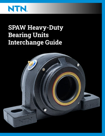
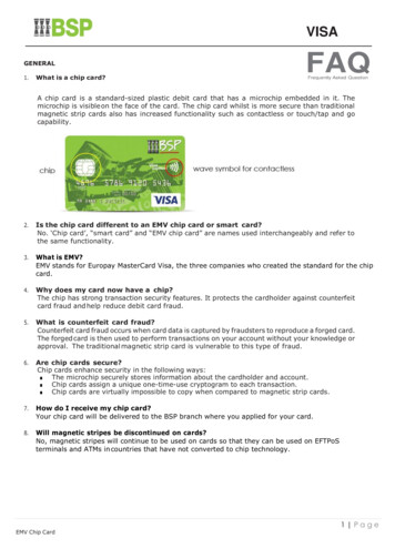
Surface Mount Multilayer Ceramic Chip Capacitors (SMD MLCCs)Capacitor Array, C0G Dielectric, 10 – 200 VDC, (Commercial & Automotive Grade)Table 3 – Chip Capacitor Array Land Pattern Design Recommendations per IPC-7351EIA SIZECODEMETRICSIZECODEDensity Level A:Maximum (Most) LandProtrusion (mm)CYXPV1Density Level B:Median (Nominal) LandProtrusion (mm)V2CYXPV1Density Level C:Minimum (Least) LandProtrusion (mm)V2CYXPV1V20508/CA05212201.601.00 0.55 1.00 3.50 3.30 1.500.90 0.50 1.00 2.90 2.80 1.400.75 0.45 1.00 2.40 2.500612/CA06416321.801.100.95 0.50 0.80 3.30 3.900.85 0.40 0.80 2.80 3.600.50 0.80 3.90 4.40 1.801.70Density Level A: For low-density product applications. Provides a wider process window for reflow solder processes.Density Level B: For products with a moderate level of component density. Provides a robust solder attachment condition for reflow solder processes.Density Level C: For high component density product applications. Before adapting the minimum land pattern variations the user should performqualification testing based on the conditions outlined in IPC Standard 7351 (IPC–7351).Image below based on Density Level B for an EIA 0612 case size.V2PXYV1CGrid Placement Courtyard KEMET Electronics Corporation P.O. Box 5928 Greenville, SC 29606 864-963-6300 www.kemet.comC1016 C0G ARRAY SMD 1/9/20178
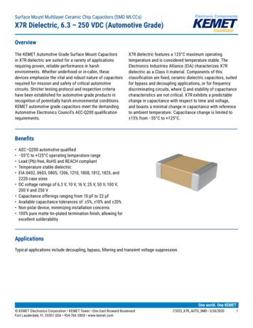
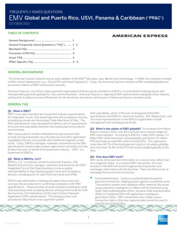
Surface Mount Multilayer Ceramic Chip Capacitors (SMD MLCCs)Capacitor Array, C0G Dielectric, 10 – 200 VDC, (Commercial & Automotive Grade)Soldering ProcessRecommended Soldering Technique: Solder reflow onlyRecommended Reflow Soldering Profile:KEMET’s families of surface mount multilayer ceramic capacitors (SMD MLCCs) are compatible with wave (single or dual),convection, IR or vapor phase reflow techniques. Preheating of these components is recommended to avoid extreme thermalstress. KEMET’s recommended profile conditions for convection and IR reflow reflect the profile conditions of the IPC/J-STD-020 standard for moisture sensitivity testing. These devices can safely withstand a maximum of three reflow passesat these conditions.Termination FinishSnPb100% Matte SnRamp-Up Rate (TL to TP)100 C150 C60 – 120 seconds3 C/secondmaximum150 C200 C60 – 120 seconds3 C/secondmaximumLiquidous Temperature (TL)183 C217 CTime Above Liquidous (tL)60 – 150 seconds60 – 150 secondsPeak Temperature (TP)235 C260 CPreheat/SoakTemperature Minimum (TSmin)Temperature Maximum (TSmax)Time (tS) from TSmin to TSmaxTPTLTemperatureProfile FeaturetPMaximum Ramp Up Rate 3ºC/secMaximum Ramp Down Rate 6ºC/sectLTsmaxTsmin25ts25ºC to PeakTimeTime Within 5 C of MaximumPeak Temperature (tP)20 seconds30 secondsmaximummaximum6 C/second6 C/secondRamp-Down Rate (TP to TL)maximummaximumTime 25 C to Peak6 minutes8 minutesTemperaturemaximummaximumNote 1: All temperatures refer to the center of the package, measured on thecapacitor body surface that is facing up during assembly reflow. KEMET Electronics Corporation P.O. Box 5928 Greenville, SC 29606 864-963-6300 www.kemet.comC1016 C0G ARRAY SMD 1/9/20179
Surface Mount Multilayer Ceramic Chip Capacitors (SMD MLCCs)Capacitor Array, C0G Dielectric, 10 – 200 VDC, (Commercial & Automotive Grade)Table 4 – Performance & Reliability: Test Methods and ConditionsStressReferenceTest or Inspection MethodTerminal StrengthJIS–C–6429Appendix 1, Note: Force of 1.8 kg for 60 seconds.Board FlexJIS–C–6429Appendix 2, Note: Standard termination system – 2.0 mm (minimum) for all except 3 mmfor C0G. Flexible termination system – 3.0 mm (minimum).Magnification 50 X. Conditions:SolderabilityJ–STD–002a) Method B, 4 hours at 155 C, dry heat at 235 Cb) Method B at 215 C category 3c) Method D, category 3 at 260 CTemperature CyclingJESD22 Method JA–104Biased HumidityMIL–STD–202 Method103Moisture ResistanceThermal ShockHigh Temperature LifeStorage LifeVibrationMechanical ShockResistance to SolventsMIL–STD–202 Method106MIL–STD–202 Method107MIL–STD–202 Method108/EIA–198MIL–STD–202 Method108MIL–STD–202 Method204MIL–STD–202 Method213MIL–STD–202 Method2151,000 Cycles ( 55 C to 125 C). Measurement at 24 hours / 4 hours after testconclusion.Load Humidity: 1,000 hours 85 C/85% RH and rated voltage. Add 100 K ohm resistor.Measurement at 24 hours / 4 hours after test conclusion.Low Volt Humidity: 1,000 hours 85 C/85% RH and 1.5 V. Add 100 K ohm resistor.Measurement at 24 hours / 4 hours after test conclusion.t 24 hours/cycle. Steps 7a and 7b not required.Measurement at 24 hours / 4 hours after test conclusion. 55 C/ 125 C. Note: Number of cycles required – 300, maximum transfer time – 20seconds, dwell time – 15 minutes. Air – Air.1,000 hours at 125 C (85 C for X5R, Z5U and Y5V) with 2 X rated voltage applied.150 C, 0 VDC for 1,000 hours.5 g's for 20 min., 12 cycles each of 3 orientations. Note: Use 8" X 5" PCB 0.031" thick 7secure points on one long side and 2 secure points at corners of opposite sides. Partsmounted within 2" from any secure point. Test from 10 – 2,000 HzFigure 1 of Method 213, Condition F.Add aqueous wash chemical, OKEM Clean or equivalent.Storage & HandlingCeramic chip capacitors should be stored in normal working environments. While the chips themselves are quite robust inother environments, solderability will be degraded by exposure to high temperatures, high humidity, corrosive atmospheres,and long term storage. In addition, packaging materials will be degraded by high temperature–reels may soften or warpand tape peel force may increase. KEMET recommends that maximum storage temperature not exceed 40ºC and maximumstorage humidity not exceed 70% relative humidity. Temperature fluctuations should be minimized to avoid condensation onthe parts and atmospheres should be free of chlorine and sulfur bearing compounds. For optimized solderability chip stockshould be used promptly, preferably within 1.5 years of receipt. KEMET Electronics Corporation P.O. Box 5928 Greenville, SC 29606 864-963-6300 www.kemet.comC1016 C0G ARRAY SMD 1/9/201710
Surface Mount Multilayer Ceramic Chip Capacitors (SMD MLCCs)Capacitor Array, C0G Dielectric, 10 – 200 VDC, (Commercial & Automotive Grade)ConstructionDetailed Cross SectionInnerElectrodes(Ni)Termination Finish(100% Matte Sn /SnPb - 5% Pb min)Barrier Layer(Ni)Epoxy Layer(Ag)End Termination/External Electrode(Cu)End Termination/DielectricMaterial (CaZrO3) External Electrode(Cu)Epoxy Layer(Ag)Barrier Layer(Ni)Termination Finish(100% Matte Sn /SnPb - 5% Pb min)InnerElectrodes(Ni)Capacitor Marking (Optional):Laser marking option is not available on: C0G, Ultra Stable X8R and Y5V dielectric devicesEIA 0402 case size devicesEIA 0603 case size devices with Flexible Termination option.KPS Commercial and Automotive grade stacked devices.These capacitors are supplied unmarked only. KEMET Electronics Corporation P.O. Box 5928 Greenville, SC 29606 864-963-6300 www.kemet.comC1016 C0G ARRAY SMD 1/9/201711
Surface Mount Multilayer Ceramic Chip Capacitors (SMD MLCCs)Capacitor Array, C0G Dielectric, 10 – 200 VDC, (Commercial & Automotive Grade)Tape & Reel Packaging InformationKEMET offers multilayer ceramic chip capacitors packaged in 8, 12 and 16 mm tape on 7" and 13" reels in accordance withEIA Standard 481. This packaging system is compatible with all tape-fed automatic pick and place systems. See Table 2 fordetails on reeling quantities for commercial chips.Bar Code LabelAnti-Static Reel Embossed Plastic* orPunched Paper Carrier.ETKEMChip and KPS Orientation in Pocket(except 1825 Commercial, and 1825 and 2225 Military)Sprocket HolesEmbossment or Punched Cavity8 mm, 12 mmor 16 mm Carrier Tape178 mm (7.00")or330 mm (13.00")Anti-Static Cover Tape(.10 mm (.004") Maximum Thickness)*EIA 01005, 0201, 0402 and 0603 case sizes available on punched paper carrier only.Table 5 – Carrier Tape Configuration, Embossed Plastic & Punched Paper (mm)EIA Case SizeTapeSize(W)*Embossed Plastic7" Reel13" ReelPitch (P1)*Punched Paper7" Reel13" ReelPitch (P1)*01005 – 0402822060382/42/40805844441206 – 1210844441805 – 18081244 18121288KPS 12101288KPS 1812 & 2220161212Array 0508 & 0612844*Refer to Figures 1 & 2 for W and P1 carrier tape reference locations.*Refer to Tables 6 & 7 for tolerance specifications.New 2 mm Pitch Reel Options*PackagingOrdering Code(C-Spec)Packaging Type/OptionsC-3190C-3191C-7081C-7082Automotive grade 7" reel unmarkedAutomotive grade 13" reel unmarkedCommercial grade 7" reel unmarkedCommercial grade 13" reel unmarked* 2 mm pitch reel only available for 0603 EIA case size.2 mm pitch reel for 0805 EIA case size under development.Benefits of Changing from 4 mm to 2 mm Pitching Spacing Lower placement costs Double the parts on each reel results in fewer reelchanges and increased efficiency Fewer reels result in lower packaging, shipping andstorage costs, reducing waste KEMET Electronics Corporation P.O. Box 5928 Greenville, SC 29606 864-963-6300 www.kemet.comC1016 C0G ARRAY SMD 1/9/201712
Surface Mount Multilayer Ceramic Chip Capacitors (SMD MLCCs)Capacitor Array, C0G Dielectric, 10 – 200 VDC, (Commercial & Automotive Grade)Figure 1 – Embossed (Plastic) Carrier Tape DimensionsP2TT2ØDo[10 pitches cumulativetolerance on tape 0.2 mm]PoE1AoFKoB1E2BoS1WP1T1Center Lines of CavityØDCover TapeB 1 is for tape feeder reference only,including draft concentric about Bo.1EmbossmentFor cavity size,see Note 1 Table 4User Direction of UnreelingTable 6 – Embossed (Plastic) Carrier Tape DimensionsMetric will governConstant Dimensions — Millimeters (Inches)Tape SizeD08 mm12 mm1.5 0.10/-0.0(0.059 0.004/0.0)16 mmD1 MinimumNote 11.0(0.039)1.5(0.059)R Reference S1 MinimumTNote 2Note 3Maximum25.0(0.984)1.75 0.104.0 0.102.0 0.050.6000.600(0.069 0.004) (0.157 0.004) (0.079 0.004)Variable Dimensions — Millimeters (Inches)Tape SizePitch8 mmSingle (4 mm)12 mmSingle (4 mm) &Double (8 mm)16 mmTriple (12 mm)B1 MaximumNote 46)10.25(0.404)14.25(0.561)FP13.5 0.054.0 0.10(0.138 0.002) (0.157 0.004)5.5 0.058.0 0.10(0.217 0.002) (0.315 0.004)7.5 0.0512.0 0.10(0.138 0.002) (0.157 mum8.3(0.327)12.3(0.484)16.3(0.642)A0,B0 & K0Note 51. The embossment hole location shall be measured from the sprocket hole controlling the location of the embossment. Dimensions of embossmentlocation and hole location shall be applied independent of each other.2. The tape with or without components shall pass around R without damage (see Figure 6).3. If S1 1.0 mm, there may not be enough area for cover tape to be properly applied (see EIA Standard 481 paragraph 4.3 section b).4. B1 dimension is a reference dimension for tape feeder clearance only.5. The cavity defined by A0, B0 and K0 shall surround the component with sufficient clearance that:(a) the component does not protrude above the top surface of the carrier tape.(b) the component can be removed from the cavity in a vertical direction without mechanical restriction, after the top cover tape has been removed.(c) rotation of the component is limited to 20 maximum for 8 and 12 mm tapes and 10 maximum for 16 mm tapes (see Figure 3).(d) lateral movement of the component is restricted to 0.5 mm maximum for 8 and 12 mm wide tape and to 1.0 mm maximum for 16 mm tape (seeFigure 4).(e) for KPS Series product, A0 and B0 are measured on a plane 0.3 mm above the bottom of the pocket.(f) see Addendum in EIA Standard 481 for standards relating to more precise taping requirements. KEMET Electronics Corporation P.O. Box 5928 Greenville, SC 29606 864-963-6300 www.kemet.comC1016 C0G ARRAY SMD 1/9/201713
Surface Mount Multilayer Ceramic Chip Capacitors (SMD MLCCs)Capacitor Array, C0G Dielectric, 10 – 200 VDC, (Commercial & Automotive Grade)Figure 2 – Punched (Paper) Carrier Tape DimensionsTPoØDo[10 pitches cumulativetolerance on tape 0.2 mm]A0FP1T1T1Top Cover TapeWE2B0Bottom Cover TapeE1GCavity Size,SeeNote 1, Table 7Center Lines of CavityBottom Cover TapeUser Direction of UnreelingTable 7 – Punched (Paper) Carrier Tape DimensionsMetric will governConstant Dimensions — Millimeters (Inches)Tape SizeD0E1P0P2T1 MaximumG Minimum8 mm1.5 0.10 -0.0(0.059 0.004 -0.0)1.75 0.10(0.069 0.004)4.0 0.10(0.157 0.004)2.0 0.05(0.079 0.002)0.10(0.004)MaximumR ReferenceNote 20.75(0.030)25(0.984)Variable Dimensions — Millimeters (Inches)Tape SizePitch8 mmHalf (2 mm)8 mmSingle (4 mm)E2 MinimumFP1T MaximumW MaximumA0 B 06.25(0.246)3.5 0.05(0.138 0.002)2.0 0.05(0.079 0.002)4.0 0.10(0.157 0.004)1.1(0.098)8.3(0.327)8.3(0.327)Note 11. The cavity defined by A0, B0 and T shall surround the component with sufficient clearance that:a) the component does not protrude beyond either surface of the carrier tape.b) the component can be removed from the cavity in a vertical direction without mechanical restriction, after the top cover tape has been removed.c) rotation of the component is limited to 20 maximum (see Figure 3).d) lateral movement of the component is restricted to 0.5 mm maximum (see Figure 4).e) see Addendum in EIA Standard 481 for standards relating to more precise taping requirements.2. The tape with or without components shall pass around R without damage (see Figure 6). KEMET Electronics Corporation P.O. Box 5928 Greenville, SC 29606 864-963-6300 www.kemet.comC1016 C0G ARRAY SMD 1/9/201714
Surface Mount Multilayer Ceramic Chip Capacitors (SMD MLCCs)Capacitor Array, C0G Dielectric, 10 – 200 VDC, (Commercial & Automotive Grade)Packaging Information Performance Notes1. Cover Tape Break Force: 1.0 Kg minimum.2. Cover Tape Peel Strength: The total peel strength of the cover tape from the carrier tape shall be:Tape WidthPeel Strength8 mm0.1 to 1.0 Newton (10 to 100 gf)12 and 16 mm0.1 to 1.3 Newton (10 to 130 gf)The direction of the pull shall be opposite the direction of the carrier tape travel. The pull angle of the carrier tape shall be165 to 180 from the plane of the carrier tape. During peeling, the carrier and/or cover tape shall be pulled at a velocity of300 10 mm/minute.3. Labeling: Bar code labeling (standard or custom) shall be on the side of the reel opposite the sprocket holes. Refer to EIAStandards 556 and 624.Figure 3 – Maximum Component Rotation TMaximum Component RotationTop ViewMaximum Component RotationSide ViewTypical Pocket CenterlineTapeMaximumWidth (mm) Rotation (8,122016 – 20010Bo T)Typical Component CenterlineAoFigure 4 – Maximum Lateral Movement8 mm & 12 mm Tape0.5 mm maximum0.5 mm maximum sTapeWidth (mm)8,1216 – 5672 – 200MaximumRotation (20105Figure 5 – Bending RadiusEmbossedCarrier16 mm Tape S)PunchedCarrier1.0 mm maximum1.0 mm maximumR KEMET Electronics Corporation P.O. Box 5928 Greenville, SC 2
KEMET's Ceramic Chip Capacitor Array in C0G dielectric is an advanced passive technology where multiple capacitor elements are integrated into one common monolithic structure. Array technology promotes reduced placement costs and increased throughput. This is achieved by alternatively placing one device rather than two or four discrete devices.