Transcription
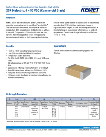
Surface Mount Multilayer Ceramic Chip Capacitors (SMD MLCCs)X7R Dielectric, 6.3 – 250 VDC (Automotive Grade)OverviewThe KEMET Automotive Grade Surface Mount Capacitorsin X7R dielectric are suited for a variety of applicationsrequiring proven, reliable performance in harshenvironments. Whether underhood or in-cabin, thesedevices emphasize the vital and robust nature of capacitorsrequired for mission and safety of critical automotivecircuits. Stricter testing protocol and inspection criteriahave been established for automotive grade products inrecognition of potentially harsh environmental conditions.KEMET automotive grade capacitors meet the demandingAutomotive Electronics Council's AEC-Q200 qualificationrequirements.X7R dielectric features a 125 C maximum operatingtemperature and is considered temperature stable. TheElectronics Industries Alliance (EIA) characterizes X7Rdielectric as a Class II material. Components of thisclassification are fixed, ceramic dielectric capacitors, suitedfor bypass and decoupling applications, or for frequencydiscriminating circuits, where Q and stability of capacitancecharacteristics are not critical. X7R exhibits a predictablechange in capacitance with respect to time and voltage,and boasts a minimal change in capacitance with referenceto ambient temperature. Capacitance change is limited to 15% from 55 C to 125 C.Benefits AEC–Q200 automotive qualified 55 C to 125 C operating temperature rangeLead (Pb)-free, RoHS and REACH compliantTemperature stable dielectricEIA 0402, 0603, 0805, 1206, 1210, 1808, 1812, 1825, and2220 case sizesDC voltage ratings of 6.3 V, 10 V, 16 V, 25 V, 50 V, 100 V,200 V and 250 VCapacitance offerings ranging from 10 pF to 22 μFAvailable capacitance tolerances of 5%, 10% and 20%Non-polar device, minimizing installation concerns100% pure matte tin-plated termination finish, allowing forexcellent solderabilityClick image above for interactive 3D contentOpen PDF in Adobe Reader for full functionalityApplicationsTypical applications include decoupling, bypass, filtering and transient voltage suppression.One world. One KEMET KEMET Electronics Corporation KEMET Tower One East Broward Boulevard Fort Lauderdale, FL 33301 USA 954-766-2800 www.kemet.comC1023 X7R AUTO SMD 3/24/20201
Surface Mount Multilayer Ceramic Chip Capacitors (SMD MLCCs)X7R Dielectric, 6.3 – 250 VDC (Automotive Grade)Ordering InformationCCeramic0805Case Size Specification/(L" x W")Series0402060308051206121018081812182522201CC Standard225CapacitanceCode (pF)Two significantdigits andnumber ofzeros.M4RACFailureCapacitance Rated VoltageDielectricTermination Finish1Tolerance(VDC)Rate/DesignJ 5%K 10%M 20%9 6.38 104 163 255 501 1002 200A 250R X7RA N/AC 100% matte SnAUTOPackaging/Grade(C-Spec)See "PackagingC-Spec OrderingOptions Table"Additional termination finish options may be available. Contact KEMET for details.Packaging C-Spec Ordering Options TablePackaging Type17" Reel13" Reel/Unmarked7" Reel/Unmarked/2 mm pitch213" Reel/Unmarked/2 mm pitch2Packaging/GradeOrdering Code (C-Spec)3AUTOAUTO7411 (EIA 0603 and smaller case sizes)AUTO7210 (EIA 0805 and larger case sizes)31903191Reeling tape options (paper or plastic) are dependent on capacitor case size (L" x W") and thickness dimension. See "Chip Thickness/Tape & ReelPackaging Quantities" and "Tape & Reel Packaging Information."2The 2 mm pitch option allows for double the packaging quantity of capacitors on a given reel size. This option is limited to EIA 0603 (1608 metric) casesize devices. For more information regarding 2 mm pitch option see "Tape & Reel Packaging Information."3All automotive packaging C-Specs listed exclude the option to laser mark components. Please contact KEMET if you require a laser marked option. Formore information see "Capacitor Marking."3For additional Information regarding "AUTO" C-Spec options, see "Automotive C-Spec e grade products meet or exceed the requirements outlined by the Automotive Electronics Council. Detailsregarding test methods and conditions are referenced in document AEC–Q200, Stress Test Qualification for PassiveComponents. For additional information regarding the Automotive Electronics Council and AEC–Q200, please visit theirwebsite at www.aecouncil.com.Environmental ComplianceLead (Pb)-free, RoHS, and REACH compliant without exemptions. KEMET Electronics Corporation KEMET Tower One East Broward Boulevard Fort Lauderdale, FL 33301 USA 954-766-2800 www.kemet.comC1023 X7R AUTO SMD 3/24/20202
Surface Mount Multilayer Ceramic Chip Capacitors (SMD MLCCs)X7R Dielectric, 6.3 – 250 VDC (Automotive Grade)Automotive C-Spec InformationKEMET automotive grade products meet or exceed the requirements outlined by the Automotive Electronics Council.Details regarding test methods and conditions are referenced in document AEC–Q200, Stress Test Qualification for PassiveComponents. These products are supported by a Product Change Notification (PCN) and Production Part Approval Processwarrant (PPAP).Automotive products offered through our distribution channel have been assigned an inclusive ordering code C-Spec, “AUTO.”This C-Spec was developed in order to better serve small and medium-sized companies that prefer an automotive gradecomponent without the requirement to submit a customer Source Controlled Drawing (SCD) or specification for review by aKEMET engineering specialist. This C-Spec is therefore not intended for use by KEMET OEM automotive customers and arenot granted the same “privileges” as other automotive C-Specs. Customer PCN approval and PPAP request levels are limited(see details below.)Product Change Notification (PCN)The KEMET product change notification system is used to communicate primarily the following types of changes: Product/process changes that affect product form, fit, function, and/or reliability Changes in manufacturing site Product obsolescenceProcess/Product changeObsolescence*Days Prior ToImplementationKEMET assignedYes (with approval and sign off)Yes180 days minimumAUTOYes (without approval)Yes90 days minimum11Customer Notification Due To:KEMET AutomotiveC-SpecKEMET assigned C-Specs require the submittal of a customer SCD or customer specification for review. For additional information contact KEMET.Production Part Approval Process (PPAP)The purpose of the Production Part Approval Process is: To ensure that supplier can meet the manufacturability and quality requirements for the purchased parts. To provide the evidence that all customer engineering design records and specification requirements are properlyunderstood and fulfilled by the manufacturing organization. To demonstrate that the established manufacturing process has the potential to produce the part.PPAP (Product Part Approval Process) LevelKEMET AutomotiveC-Spec12345KEMET assigned1 AUTO1 KEMET assigned C-Specs require the submittal of a customer SCD or customer specification for review. For additional information contact KEMET. Part number specific PPAP available Product family PPAP only KEMET Electronics Corporation KEMET Tower One East Broward Boulevard Fort Lauderdale, FL 33301 USA 954-766-2800 www.kemet.comC1023 X7R AUTO SMD 3/24/20203
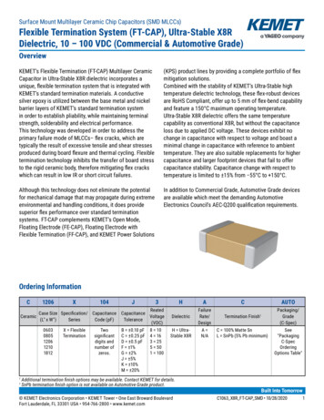
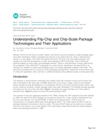
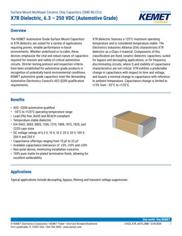
Surface Mount Multilayer Ceramic Chip Capacitors (SMD MLCCs)X7R Dielectric, 6.3 – 250 VDC (Automotive Grade)Dimensions – Millimeters (Inches)LWBTSEIA SizeCodeMetric SizeCode040210050603116080805220121206332161210 432251812453222205650LLengthWWidth1.00 (0.040) 0.05 (0.002)1.60 (0.063) 0.15 (0.006)2.00 (0.079) 0.20 (0.008)3.20 (0.126) 0.20 (0.008)3.20 (0.126) 0.20 (0.008)4.50 (0.177) 0.30 (0.012)5.70 (0.224) 0.40 (0.016)0.50 (0.020) 0.05 (0.002)0.80 (0.032) 0.15 (0.006)1.25 (0.049) 0.20 (0.008)1.60 (0.063) 0.20 (0.008)2.50 (0.098) 0.20 (0.008)3.20 (0.126) 0.30 (0.012)5.00 (0.197) 0.40 (0.016)TThicknessBBandwidthSee Table 2 forThickness0.30 (0.012) 0.10 (0.004)0.35 (0.014) 0.15 (0.006)0.50 (0.02) 0.25 (0.010)0.50 (0.02) 0.25 (0.010)0.50 (0.02) 0.25 (0.010)0.60 (0.024) 0.35 (0.014)0.60 (0.024) 0.35 (0.014)SSeparationMinimumMountingTechnique0.30 (0.012)Solder reflow only0.70 (0.028)0.75 (0.030)N/ASolder wave orSolder reflowSolder reflowonlyFor capacitance values 0.56 µF add 0.05 (0.002) to length tolerance dimension.For capacitance values 1.0 µF or 2.7 µF add 0.10 (0.004) to length tolerance dimension.3For capacitance value 1.0 µF all voltages and 10 µF with 25 V add 0.05 (0.002) to length tolerance dimension.4For capacitance values 4.7 µF add 0.02 (0.001) to the width tolerance dimension and 0.10 (0.004) to the length tolerance dimension.For capacitance value 22 µF, Length is [L] 3.30 (0.130) 0.40 (0.016) and Width [W] is 2.60 (0.102) 0.30 (0.012).12 KEMET Electronics Corporation KEMET Tower One East Broward Boulevard Fort Lauderdale, FL 33301 USA 954-766-2800 www.kemet.comC1023 X7R AUTO SMD 3/24/20204
Surface Mount Multilayer Ceramic Chip Capacitors (SMD MLCCs)X7R Dielectric, 6.3 – 250 VDC (Automotive Grade)Electrical isticsOperating Temperature Range 55 C to 125 CCapacitance Change with Reference to 25 C and 0 VDC Applied (TCC) 15%Aging Rate (Maximum % Capacitance Loss/Decade Hour)3.0%1234Dielectric Withstanding Voltage (DWV)Dissipation Factor (DF) Maximum Limit at 25 CInsulation Resistance (IR) Minimum Limit at 25 C250% of rated voltage(5 1 seconds and charge/discharge not exceeding 50 mA)See Dissipation Factor Limit TableSee Insulation Resistance Limit Table(Rated voltage applied for 120 5 seconds at 25 C)Regarding Aging Rate: Capacitance measurements (including tolerance) are indexed to a referee time of 1,000 hours.DWV is the voltage a capacitor can withstand (survive) for a short period of time. It exceeds the nominal and continuous working voltage of thecapacitor.3Capacitance and dissipation factor (DF) measured under the following conditions:1 kHz 50 Hz and 1.0 0.2 Vrms if capacitance 10 µF120 Hz 10 Hz and 0.5 0.1 Vrms if capacitance 10 µF4To obtain IR limit, divide MΩ-µF value by the capacitance and compare to GΩ limit. Select the lower of the two limits.Note: When measuring capacitance it is important to ensure the set voltage level is held constant. The HP4284 and Agilent E4980 have a feature knownas Automatic Level Control (ALC). The ALC feature should be switched to "ON."12Insulation Resistance Limit TableEIA Case SizeRated DC Voltage1,000 megohmmicrofarads or 100 GΩ500 megohmmicrofarads or 10 GΩ100 megohmmicrofarads or 10 GΩ0402ALL 200 V250 V 200 V250 V 200 V250 V 200 V250 VALLALLALLALLALL 0.012 µF 0.047 µFN/A 0.15 µF .027 µF 0.47 µF 0.12 µF 0.39 µF 0.27 µFALL 2.2 µFALL 10 µFALL 0.012 µF 0.047 µf 0.47 µfN/A 0.15 µF 2.2 µfN/A 0.47 µF 2.2 µfN/A 0.39 µF 10 µfN/AN/A 2.2 µFN/A 10 µFN/AN/A 0.47 µfALL 2.2 µf .027 µF 2.2 µf 0.12 µF 10 µf 0.27 2225 KEMET Electronics Corporation KEMET Tower One East Broward Boulevard Fort Lauderdale, FL 33301 USA 954-766-2800 www.kemet.comC1023 X7R AUTO SMD 3/24/20205
Surface Mount Multilayer Ceramic Chip Capacitors (SMD MLCCs)X7R Dielectric, 6.3 – 250 VDC (Automotive Grade)Dissipation Factor (DF) Limits TableEIA Case Size040206031Rated DCVoltage 1616/25 25 1616/25 25All 1608052161206325 25 1616/25 25 16161210 425 25Capacitance 1.0 µF 4.7 µF 4.7 µF 4.7 µF 4.7 0.03.510.03.52.55.03.52.55.03.5 10 µF3.5 10 µF10.0All2.5All 1.0 µF5.0 161808 - 222516/25 25DissipationFactor(Maximum %)All3.52.5For Capacitance values 0.22uF (16 and 25 Volts) DF is 5%.For Capacitance values 2.2µF (6.3, 10, and 16 Volts) and 4.7µF (25 Volts) DF is 10%.3For Capacitance values 4.7 and 10 µF (All Voltages) and 2.2uF (25 and 50 Volts) DF is 10%.4For Capacitance values 10 µF ( 16 Volts) DF is 10%.12 KEMET Electronics Corporation KEMET Tower One East Broward Boulevard Fort Lauderdale, FL 33301 USA 954-766-2800 www.kemet.comC1023 X7R AUTO SMD 3/24/20206
Surface Mount Multilayer Ceramic Chip Capacitors (SMD MLCCs)X7R Dielectric, 6.3 – 250 VDC (Automotive Grade)Post Environmental LimitsHigh Temperature Life, Biased Humidity, Moisture ResistanceEIA Case Size0402RatedDC VoltageCapacitanceDissipationFactor(Maximum %) 16All7.516/25All5.0 25All3.0 160603116/2508052120631210 41808 – 2225 1.0 µF 4.7 µF7.5 4.7 µF20.0 4.7 µF5.0 4.7 µF20.025All5.0 25All3.0 16All7.516/25All5.0 25All3.0 16All7.516All5.0 10 µF5.0 10 µF20.0 25All3.0 16All7.516/25All5.0 25All3.02510% of Initiallimit3.020.016 20%5.0 1.0 µF 16InsulationResistance7.5 25AllCapacitanceShiftFor Capacitance values 0.22uF (16 and 25 Volts) DF is 7.5%.For Capacitance values 2.2µF (6.3, 10, and 16 Volts) and 4.7µF (25 Volts) DF is 20%3For Capacitance values 4.7 and 10 µF (All Voltages) and 2.2uF (25 and 50 Volts) DF is 20%12 KEMET Electronics Corporation KEMET Tower One East Broward Boulevard Fort Lauderdale, FL 33301 USA 954-766-2800 www.kemet.comC1023 X7R AUTO SMD 3/24/20207
Surface Mount Multilayer Ceramic Chip Capacitors (SMD MLCCs)X7R Dielectric, 6.3 – 250 VDC (Automotive Grade)Table 1A – Capacitance Range/Selection Waterfall (0402 – 1206 Case Sizes)Case BBBBBBBBBBBBBB100Product Availability and Chip Thickness Codes – See Table 2 for Chip Thickness Dimensions12A9843512C0402C25350416810950CJ¹ CJ¹ CJ¹6.3Cap Code Voltage Code816Capacitance925Rated Voltage(VDC)C0805C10CapacitanceTolerance100 - 910* JKM101 - 151** JKM181 - 820** 75JKMKM335J395JKMC0603C6.3Voltage CodeRated Voltage(VDC)1010 - 91 pF*100 - 150 pF**180 - 820 pF**1,000 pF1,200 pF1,500 pF1,800 pF2,200 pF2,700 pF3,300 pF3,900 pF4,700 pF5,600 pF6,800 pF8,200 pF10,000 pF12,000 pF15,000 pF18,000 pF22,000 pF27,000 pF33,000 pF39,000 pF47,000 pF56,000 pF68,000 pF82,000 pF0.10 µF0.12 µF0.15 µF0.18 µF0.22 µF0.27 µF0.33 µF0.39 µF0.47 µF0.56 µF0.68 µF0.82 µF1.0 µF1.2 µF1.5 µF1.8 µF2.2 µF2.7 µF3.3 µF3.9 µFCapCode6.3CapacitanceC0402C6.3Case Size/Series598435C0603CC0805CC1206C*Capacitance range includes E24 decade values only (i.e., 10, 11, 12, 13, 15, 16, 18, 20, 22, 24, 27, 30, 33, 36, 39, 43, 47, 51, 56, 62, 68, 75, 82, and 91.)**Capacitance range includes E12 decade values only. (i.e., 10, 12, 15, 18, 22, 27, 33, 39, 47, 56, 68, and 82.)xx1 Available only in K and M tolerances. KEMET Electronics Corporation KEMET Tower One East Broward Boulevard Fort Lauderdale, FL 33301 USA 954-766-2800 www.kemet.comC1023 X7R AUTO SMD 3/24/20208
Surface Mount Multilayer Ceramic Chip Capacitors (SMD MLCCs)X7R Dielectric, 6.3 – 250 VDC (Automotive Grade)Table 1A – Capacitance Range/Selection Waterfall (0402 – 1206 Case Sizes) ceJKMJKMJKMJKMJKMProduct Availability and Chip Thickness Codes – See Table 2 for Chip Thickness DimensionsDG DG DG DHCase Size/SeriesC0402C35C0603C1641086.39EH EH EHEHEHEHEH 420081009255503164108509Cap Code Voltage Code6.3DH DH16Rated tage CodeRated Voltage(VDC)104.7 µF5.6 µF6.8 µF8.2 µF10 µFCapCode6.3CapacitanceC0402C50Case Size/Series12A984C0805CC1206C*Capacitance range Includes E24 decade values only. (i.e., 10, 11, 12, 13, 15, 16, 18, 20, 22, 24, 27, 30, 33, 36, 39, 43, 47, 51, 56, 62, 68, 75, 82 and 91)**Capacitance range Includes E12 decade values only. (i.e., 10, 12, 15, 18, 22, 27, 33, 39, 47, 56, 68 and 82)xx¹ Available only in K andM tolerance.Table 1B – Capacitance Range/Selection Waterfall (1210 – 2220 Case Sizes)Case 00200250Product Availability and Chip Thickness Codes – See Table 2 for Chip Thickness Dimensions250Cap Code Voltage CodeA200Capacitance2100Rated MC1825C525Rated Voltage(VDC)C1812C316416810910100 - 910*101 - 271**331391471 - Voltage Code6.310 - 91 pF*100 - 270 pF**330 pF390 pF470 - 820 pF**1,000 pF1,200 pF1,500 pF1,800 pF2,200 pF2,700 pF3,300 pF3,900 pF4,700 pF5,600 pF6,800 pF8,200 pF10,000 pF12,000 pF15,000 pFCapCodeC1808C6.3CapacitanceC1210C25Case Size/Series2A5123512A512AC1808CGB GB GB GBGB GB GB GBGB GB GB GBGB GB GB GBGB GB GB GBGB GB GB GBGB GB GB GBGB GB GB GBGB GB GB GBGB GB GB GDGB GB GB GHGB GB GB GB GBGB GB GB GB GBGB GB GB GB GBGB GB GB GB GBGB GB GB GB GBC1812CC1825CC2220C*Capacitance range Includes E24 decade values only. (i.e., 10, 11, 12, 13, 15, 16, 18, 20, 22, 24, 27, 30, 33, 36, 39, 43, 47, 51, 56, 62, 68, 75, 82 and 91)**Capacitance range Includes E12 decade values only. (i.e., 10, 12, 15, 18, 22, 27, 33, 39, 47, 56, 68 and 82) KEMET Electronics Corporation KEMET Tower One East Broward Boulevard Fort Lauderdale, FL 33301 USA 954-766-2800 www.kemet.comC1023 X7R AUTO SMD 3/24/20209
Surface Mount Multilayer Ceramic Chip Capacitors (SMD MLCCs)X7R Dielectric, 6.3 – 250 VDC (Automotive Grade)Table 1B – Capacitance Range/Selection Waterfall (1210 – 2220 Case Sizes) cont.Case DFDFDFDFFFHFHFHFHFJFEFFFGFCFFFGFHFSFSFB FB FB FB FB FBFB FB FB FB FB FBFB FB FB FB FB FBFB FB FB FB FB FBFB FB FB FB FB FBFB FB FB FB FB FBFB FB FB FB FC FCFB FB FB FB FC FCFB FB FB FC FF FFFB FB FB FD FG FGFB FB FB FD FH FHFC FC FC FD FM FMFC FC FC FD FK FKFC FC FC FD FK FKFC FC FC FD FP FPFD FD FD FD FM FMFD FD FD FD FK FKFD FD FD FD FS FSFD FD FD FFFD FD FD FGFF FF FF FLFH FH FH FMFH FH FG FHFH FH FG FMFH FH FG FJFJ FJ FG FKFE FG FHFF FM FMFG FG FKFC FG FSFF FHFG FMFH FKFS roduct Availability and Chip Thickness Codes – See Table 2 for Chip Thickness Dimensions509843512A51235C1210CLDLDLDLDLDLDLDGB GB GBGB GB GBGB GB GBGB GB GBGB GB GBGB GB GBGB GB GBGB GB GBGB GB GBGB GB GBGB GB GBGB GB GBGB GB GBGB GB GBGB GB GGGB GB GGGB GB GGGB GB GGGC GC GGGC GC GGGE GE GGGE GE GGGB GB GBGC GC GCGE GE GEGO GO GGGJ GJ GJGL GL GLGK GKGK HFJFC1808C250501002002502550JO100GK200Cap Code Voltage Code225Capacitance125010Rated tage CodeRated Voltage(VDC)C1812C1018,000 pF22,000 pF27,000 pF33,000 pF39,000 pF47,000 pF56,000 pF68,000 pF82,000 pF0.10 µF0.12 µF0.15 µF0.18 µF0.22 µF0.27 µF0.33 µF0.39 µF0.47 µF0.56 µF0.68 µF0.82 µF1.0 µF1.2 µF1.5 µF1.8 µF2.2 µF2.7 µF3.3 µF3.9 µF4.7 µF5.6 µF6.8 µF8.2 µF10 µF22 µFCapCodeC1808C6.3CapacitanceC1210C200Case Size/Series12A512A35C1812CC1825CC2220C*Capacitance range Includes E24 decade values only. (i.e., 10, 11, 12, 13, 15, 16, 18, 20, 22, 24, 27, 30, 33, 36, 39, 43, 47, 51, 56, 62, 68, 75, 82 and 91)**Capacitance range Includes E12 decade values only. (i.e., 10, 12, 15, 18, 22, 27, 33, 39, 47, 56, 68 and 82) KEMET Electronics Corporation KEMET Tower One East Broward Boulevard Fort Lauderdale, FL 33301 USA 954-766-2800 www.kemet.comC1023 X7R AUTO SMD 3/24/202010
Surface Mount Multilayer Ceramic Chip Capacitors (SMD MLCCs)X7R Dielectric, 6.3 – 250 VDC (Automotive Grade)Table 2 – Chip Thickness/Tape & Reel Packaging QuantitiesPaper Quantity1Plastic QuantityThicknessCodeCaseSize1Thickness Range (mm)7" Reel13" Reel7" Reel13" 10121012101210121012101210121012100.50 0.050.80 0.07*0.80 0.15*0.78 0.10*0.90 0.10*1.00 0.101.25 0.151.25 0.200.78 0.100.90 0.100.95 0.101.00 0.101.10 0.101.20 0.151.25 0.151.60 0.151.60 0.200.78 0.100.90 0.100.95 0.101.00 0.101.10 0.101.25 0.151.40 0.151.55 0.151.60 0.201.70 0.201.85 0.202.10 0.202.50 nessCodeCaseSize1Thickness Range (mm)7" Reel13" Reel7" Reel13" ReelPaper Quantity1Plastic QuantityPackage quantity based on finished chip thickness specifications.1If ordering using the 2 mm Tape & Reel pitch option, the packaging quantity outlined in the table above will be doubled. This option is limited to EIA 0603(1608 metric) case size devices. For more information regarding 2 mm pitch option see "Tape & Reel Packaging Information." KEMET Electronics Corporation KEMET Tower One East Broward Boulevard Fort Lauderdale, FL 33301 USA 954-766-2800 www.kemet.comC1023 X7R AUTO SMD 3/24/202011
Surface Mount Multilayer Ceramic Chip Capacitors (SMD MLCCs)X7R Dielectric, 6.3 – 250 VDC (Automotive Grade)Table 2 – Chip Thickness/Tape & Reel Packaging Quantities cont.Paper Quantity1Plastic QuantityThicknessCodeCaseSize1Thickness Range (mm)7" Reel13" Reel7" Reel13" 1218121825182518252220222022202220222022200.90 0.101.00 0.150.90 0.101.00 0.151.00 0.101.10 0.101.25 0.151.30 0.101.40 0.151.55 0.101.60 0.201.70 0.151.90 0.202.50 0.201.10 0.151.30 0.151.50 0.151.00 0.151.10 0.151.30 0.151.40 0.151.50 0.152.40 Thickness Range (mm)7" Reel13" Reel7" Reel13" ReelPaper Quantity1Plastic QuantityPackage quantity based on finished chip thickness specifications.1If ordering using the 2 mm Tape & Reel pitch option, the packaging quantity outlined in the table above will be doubled. This option is limited to EIA 0603(1608 metric) case size devices. For more information regarding 2 mm pitch option see "Tape & Reel Packaging Information." KEMET Electronics Corporation KEMET Tower One East Broward Boulevard Fort Lauderdale, FL 33301 USA 954-766-2800 www.kemet.comC1023 X7R AUTO SMD 3/24/202012
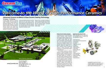
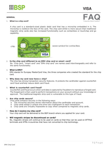
Surface Mount Multilayer Ceramic Chip Capacitors (SMD MLCCs)X7R Dielectric, 6.3 – 250 VDC (Automotive Grade)Table 3 – Chip Capacitor Land Pattern Design Recommendations per IPC–7351EIASizeCodeMetricSizeCode0402Density Level A:Maximum (Most)Land Protrusion (mm)Density Level B:Median (Nominal)Land Protrusion (mm)Density Level C:Minimum (Least)Land Protrusion 1.305.306.605.60Only for capacitance values 22 µFDensity Level A: For low-density product applications. Recommended for wave solder applications and provides a wider process window for reflowsolder processes. KEMET only recommends wave soldering of EIA 0603, 0805, and 1206 case sizes.Density Level B: For products with a moderate level of component density. Provides a robust solder attachment condition for reflow solder processes.Density Level C: For high component density product applications. Before adapting the minimum land pattern variations the user should performqualification testing based on the conditions outlined in IPC Standard 7351 (IPC–7351).1Image below based on Density Level B for an EIA 1210 case size.V1YYXXCCV2Grid Placement Courtyard KEMET Electronics Corporation KEMET Tower One East Broward Boulevard Fort Lauderdale, FL 33301 USA 954-766-2800 www.kemet.comC1023 X7R AUTO SMD 3/24/202013
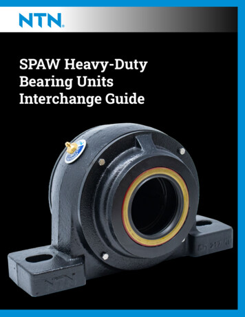
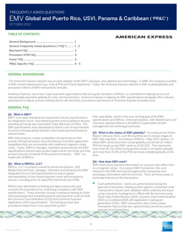
Surface Mount Multilayer Ceramic Chip Capacitors (SMD MLCCs)X7R Dielectric, 6.3 – 250 VDC (Automotive Grade)Soldering ProcessRecommended Soldering Technique: Solder wave or solder reflow for EIA case sizes 0603, 0805 and 1206 All other EIA case sizes are limited to solder reflow onlyRecommended Reflow Soldering Profile:The KEMET families of surface mount multilayer ceramic capacitors (SMD MLCCs) are compatible with wave (single or dual),convection, IR or vapor phase reflow techniques. Preheating of these components is recommended to avoid extreme thermalstress. The KEMET recommended profile conditions for convection and IR reflow reflect the profile conditions of the IPC/J-STD-020 standard for moisture sensitivity testing. These devices can safely withstand a maximum of three reflow passesat these conditions.Preheat/SoakTemperature Minimum (TSmin)Temperature Maximum (TSmax)Time (tS) from TSmin to TSmaxTermination FinishSnPbTP100% Matte SnRamp-Up Rate (TL to TP)100 C150 C60 – 120 seconds3 C/secondmaximum150 C200 C60 – 120 seconds3 C/secondmaximumLiquidous Temperature (TL)183 C217 CTime Above Liquidous (tL)60 – 150 seconds60 – 150 secondsPeak Temperature (TP)235 C260 CTLTemperatureProfile FeaturetPMaximum Ramp-up Rate 3 C/secondMaximum Ramp-down Rate 6 C/secondtLTsmaxTsmin25ts25 C to PeakTimeTime Within 5 C of MaximumPeak Temperature (tP)20 seconds30 secondsmaximummaximum6 C/second6 C/secondRamp-Down Rate (TP to TL)maximummaximumTime 25 C to Peak6 minutes8 minutesTemperaturemaximummaximumNote: All temperatures refer to the center of the package, measured on thecapacitor body surface that is facing up during assembly reflow.Storage & HandlingCeramic chip capacitors should be stored in normal working environments. While the chips themselves are quite robust inother environments, solderability will be degraded by exposure to high temperatures, high humidity, corrosive atmospheres,and long term storage. In addition, packaging materials will be degraded by high temperature – reels may soften or warpand tape peel force may increase. KEMET recommends that maximum
For capacitance values 1.0 µF or 2.7 µF add 0.10 (0.004) to length tolerance dimension. 3. For capacitance value 1.0 µF all voltages and 10 µF with 25 V add 0.05 (0.002) to length tolerance dimension. 4. For capacitance values 4.7 µF add 0.02 (0.001) to the width tolerance dimension and 0.10 (0.004) to the length tolerance dimension.