Transcription
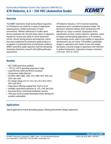
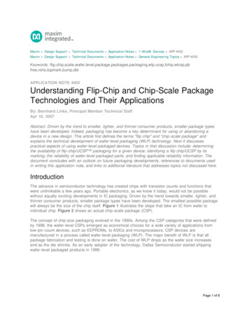
Surface Mount Multilayer Ceramic Chip Capacitors (SMD MLCCs)X5R Dielectric, 4 – 50 VDC (Commercial Grade)OverviewKEMET’s X5R dielectric features an 85 C maximumoperating temperature and is considered “semi-stable.”The Electronics Components, Assemblies & MaterialsAssociation (EIA) characterizes X5R dielectric as a ClassII material. Components of this classification are fixed,ceramic dielectric capacitors suited for bypass anddecoupling applications or for frequency discriminatingcircuits where Q and stability of capacitance characteristicsare not critical. X5R exhibits a predictable change incapacitance with respect to time and voltage and boasts aminimal change in capacitance with reference to ambienttemperature. Capacitance change is limited to 15% from 55 C to 85 C.BenefitsApplications Typical applications include decoupling, bypass, andfiltering. 55 C to 85 C operating temperature rangeLead (Pb)-free, RoHS and REACH compliantTemperature stable dielectricEIA 0201, 0402, 0603, 0805, 1206, 1210, and 1812 casesizesDC voltage ratings of 4 V, 6.3 V, 10 V, 16 V, 25 V, 35 V, and50 VCapacitance offerings ranging from 0.01 μF to 100 μFAvailable capacitance tolerances of 10% and 20%Non-polar device, minimizing installation concerns100% pure matte tin-plated termination finish allowing forexcellent solderabilityClick image above for interactive 3D contentOpen PDF in Adobe Reader for full functionalityOrdering InformationCCeramic1206107Case Size Specification/ Capacitance(L" x W")SeriesCode (pF)0201040206030805120612101CC StandardTwosignificantdigits number ofzeros.M9PACTUFailure Rate/Capacitance Rated VoltagePackaging/GradeTermination Finish1DielectricDesignTolerance(VDC)(C–Spec)K 10%M 20%7 49 6.38 104 163 256 355 50P X5RA N/AC 100% Matte SnSee"PackagingC-SpecOrderingOptions Table"belowAdditional termination finish options may be available. Contact KEMET for details.One world. One KEMET KEMET Electronics Corporation P.O. Box 5928 Greenville, SC 29606 864-963-6300 www.kemet.comC1006 X5R SMD 11/15/20161
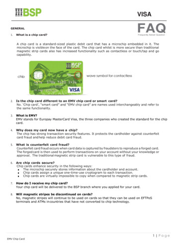
Surface Mount Multilayer Ceramic Chip Capacitors (SMD MLCCs)X5R Dielectric, 4 – 50 VDC (Commercial Grade)Packaging C-Spec Ordering Options TablePackaging/GradeOrdering Code (C-Spec)Packaging Type1Bulk Bag/Unmarked7" Reel/Unmarked13" Reel/Unmarked7" Reel/Marked13" Reel/Marked7" Reel/Unmarked/2mm pitch213" Reel/Unmarked/2mm pitch2Not required (Blank)TU7411 (EIA 0603 and smaller case sizes)7210 (EIA 0805 and larger case sizes)TM7040 (EIA 0603 and smaller case sizes)7215 (EIA 0805 and larger case sizes)70817082Default packaging is "Bulk Bag". An ordering code C-Spec is not required for "Bulk Bag" packaging.The terms "Marked" and "Unmarked" pertain to laser marking option of capacitors. All packaging options labeled as "Unmarked" will contain capacitorsthat have not been laser marked. Please contact KEMET if you require a laser marked option. For more information see "Capacitor Marking".2The 2 mm pitch option allows for double the packaging quantity of capacitors on a given reel size. This option is limited to EIA 0603 (1608 metric) casesize devices. For more information regarding 2 mm pitch option see "Tape & Reel Packaging Information".11Dimensions – Millimeters (Inches)LWBTSEIA SizeCodeMetric 121033225LLengthWWidth0.60 (0.024) 0.03 (0.001)1.00 (0.040) 0.05 (0.002)1.60 (0.063) 0.15 (0.006)2.00 (0.079) 0.20 (0.008)3.20 (0.126) 0.20 (0.008)3.20 (0.126) 0.20 (0.008)0.30 (0.012) 0.03 (0.001)0.50 (0.020) 0.05 (0.002)0.80 (0.032) 0.15 (0.006)1.25 (0.049) 0.20 (0.008)1.60 (0.063) 0.20 (0.008)2.50 (0.098) 0.20 (0.008)TThicknessBBandwidthSee Table 2 forThickness0.15 (0.006) 0.05 (0.002)0.30 (0.012) 0.10 (0.004)0.35 (0.014) 0.15 (0.006)0.50 (0.02) 0.25 (0.010)0.50 (0.02) 0.25 (0.010)0.50 (0.02) 0.25 (0.010)SSeparationMinimumN/A0.30 (0.012)MountingTechniqueSolder ReflowOnly0.70 (0.028)0.75 (0.030)N/ASolder Wave orSolder ReflowSolder ReflowOnlyFor capacitance values 4.7 µF add 0.15 (0.006) to the width and length tolerance dimensions.For capacitance values 22 µF add 0.10 (0.004) to the positive bandwidth tolerance dimension.3For capacitance values 22 µF add 0.10 (0.004) to the length and width tolerance dimension and add 0.15 (0.006) to the positive bandwidth tolerancedimension.12 KEMET Electronics Corporation P.O. Box 5928 Greenville, SC 29606 864-963-6300 www.kemet.comC1006 X5R SMD 11/15/20162
Surface Mount Multilayer Ceramic Chip Capacitors (SMD MLCCs)X5R Dielectric, 4 – 50 VDC (Commercial Grade)Qualification/CertificationCommercial Grade products are subject to internal qualification. Details regarding test methods and conditions arereferenced in Table 4, Performance & Reliability.Environmental ComplianceLead (Pb)-free, RoHS, and REACH compliant without exemptions.Electrical isticsOperating Temperature Range 55 C to 85 CCapacitance Change with Reference to 25 C and 0 Vdc Applied (TCC) 15%Aging Rate (Maximum % Capacitance Loss/Decade Hour)5.0%1234Dielectric Withstanding Voltage (DWV)Dissipation Factor (DF) Maximum Limit at 25 CInsulation Resistance (IR) Minimum Limit at 25 C250% of rated voltage(5 1 seconds and charge/discharge not exceeding 50mA)See Dissipation Factor Limit TableSee Insulation Resistance Limit Table(Rated voltage applied for 120 5 seconds at 25 C)Regarding Aging Rate: Capacitance measurements (including tolerance) are indexed to a referee time of 48 or 1,000 hours. Please refer to a partnumber specific datasheet for referee time details.2DWV is the voltage a capacitor can withstand (survive) for a short period of time. It exceeds the nominal and continuous working voltage of thecapacitor.3Capacitance and dissipation factor (DF) measured under the following conditions:1 kHz 50 Hz and 1.0 0.2 Vrms if capacitance 10 µF120 Hz 10 Hz and 0.5 0.1 Vrms if capacitance 10 µF4To obtain IR limit, divide MΩ-µF value by the capacitance and compare to GΩ limit. Select the lower of the two limits.Note: When measuring capacitance it is important to ensure the set voltage level is held constant. The HP4284 and Agilent E4980 have a feature knownas Automatic Level Control (ALC). The ALC feature should be switched to "ON."1 KEMET Electronics Corporation P.O. Box 5928 Greenville, SC 29606 864-963-6300 www.kemet.comC1006 X5R SMD 11/15/20163
Surface Mount Multilayer Ceramic Chip Capacitors (SMD MLCCs)X5R Dielectric, 4 – 50 VDC (Commercial Grade)Post Environmental LimitsHigh Temperature Life, Biased Humidity, Moisture ResistanceDielectricX5RRated DCVoltageCapacitanceValueDissipation Factor(Maximum %) 25All3.0 2.2 µF7.5 2.2 µF20.0 25 0.56 µF7.5 25 0.56 µF20.025CapacitanceShiftInsulationResistance 20%10% of InitialLimitDissipation Factor Limit TableRatedDC VoltageCapacitanceDissipation Factor(Maximum %) 25All2.5 2.2 µF5.0 2.2 µF10.0 0.56 µF5.0 0.56 µF10.025 25Insulation Resistance Limit TableEIA Case Size1,000 MegohmMicrofarads or 100 GΩ500 MegohmMicrofarads or 10 GΩ100 MegohmMicrofarads0201N/AALLN/A0402 .012 µF .012 µF 1.0 µF 1.0 µF0603 .047 µF .047 µf 1.0 µF 1.0 µF0805 0.15 µF 0.15 µF 1.0 µF 1.0 µF1206 0.47 µF 0.47 µF 1.0 µF 1.0 µF1210 0.39 µF 0.39 µF 1.0 µF 1.0 µF1812 2.2 µF 2.2 µFN/A KEMET Electronics Corporation P.O. Box 5928 Greenville, SC 29606 864-963-6300 www.kemet.comC1006 X5R SMD 11/15/20164
Surface Mount Multilayer Ceramic Chip Capacitors (SMD MLCCs)X5R Dielectric, 4 – 50 VDC (Commercial Grade)Table 1 – Capacitance Range/Selection Waterfall (0201 – 0805 Case Sizes)984798435798435798435Rated Voltage (VDC)101646.31016255046.31016255046.310162550Case Size/SeriesABABProduct Availability and Chip Thickness Codes – See Table 2 for Chip Thickness CGCGCGCGBBBBBBBBBBBB BB¹CGCGCGCGBB¹CGCGBE¹ BE¹CGCGBF¹ BF¹CG¹ CG¹ DG1016255046.31016255046.310162550DG DG DH¹DH¹ DH¹6.3Voltage CodeAB4Rated Voltage 5685825106126156186226476C0603CVoltage Code6.310,000 pF12,000 pF15,000 pF18,000 pF22,000 pF27,000 pF33,000 pF39,000 pF47,000 pF56,000 pF68,000 pF82,000 pF0.10 µF0.12 µF0.15 µF0.18 µF0.22 µF0.27 µF0.33 µF0.39 µF0.47 µF0.56 µF0.68 µF0.82 µF1.0 µF1.2 µF1.5 µF1.8 µF2.2 µF2.7 µF3.3 µF3.9 µF4.7 µF5.6 µF6.8 µF8.2 µF10 µF12 µF15 µF18 µF22 µF47 µFC0402C4CapacitanceCodeC0201C6.3CapacitanceCase CC0805Cxx¹ Available only in M tolerance. KEMET Electronics Corporation P.O. Box 5928 Greenville, SC 29606 864-963-6300 www.kemet.comC1006 X5R SMD 11/15/20165
Surface Mount Multilayer Ceramic Chip Capacitors (SMD MLCCs)X5R Dielectric, 4 – 50 VDC (Commercial Grade)Table 1 – Capacitance Range/Selection Waterfall (1206 – 1812 Case FHFJFTFEFJFGFT5984C1206C508GK359FS25Voltage CodeFT50Rated Voltage ECEFEHEDEHEKEKEDEHCase 4755656858251061261561862264761073Product Availability and Chip Thickness Codes – See Table 2 for Chip Thickness DimensionsCap Tolerance0.27 µF0.33 µF0.39 µF0.47 µF0.56 µF0.68 µF0.82 µF1.0 µF1.2 µF1.5 µF1.8 µF2.2 µF2.7 µF3.3 µF3.9 µF4.7 µF5.6 µF6.8 µF8.2 µF10 µF12 µF15 µF18 µF22 µF47 µF100 µF450Rated Voltage (VDC)8259C1812C16Voltage e Size/Series365365FSC1210CC1812Cxx¹ Available only in M tolerance. KEMET Electronics Corporation P.O. Box 5928 Greenville, SC 29606 864-963-6300 www.kemet.comC1006 X5R SMD 11/15/20166
Surface Mount Multilayer Ceramic Chip Capacitors (SMD MLCCs)X5R Dielectric, 4 – 50 VDC (Commercial Grade)Table 2A – Chip Thickness/Tape & Reel Packaging QuantitiesPaper Quantity1Plastic QuantityThicknessCodeCaseSize1Thickness Range (mm)7" Reel13" Reel7" Reel13" 06120612101210121012101210121012101210121018120.30 0.030.50 0.050.50 0.150.50 0.200.80 0.10*0.80 0.15*0.80 0.200.78 0.10*0.90 0.10*0.95 0.101.00 0.101.10 0.101.25 0.151.25 0.200.78 0.100.80 0.100.90 0.101.00 0.101.10 0.101.20 0.151.20 0.201.60 0.200.95 0.101.00 0.101.10 0.101.25 0.151.55 0.151.85 0.201.90 0.202.10 0.202.50 0.301.60 s Range (mm)7" Reel13" Reel7" Reel13" ReelPaper Quantity1Plastic QuantityPackage quantity based on finished chip thickness specifications.1If ordering using the 2 mm Tape and Reel pitch option, the packaging quantity outlined in the table above will be doubled. This option is limited to EIA0603 (1608 metric) case size devices. For more information regarding 2 mm pitch option see “Tape & Reel Packaging Information”. KEMET Electronics Corporation P.O. Box 5928 Greenville, SC 29606 864-963-6300 www.kemet.comC1006 X5R SMD 11/15/20167
Surface Mount Multilayer Ceramic Chip Capacitors (SMD MLCCs)X5R Dielectric, 4 – 50 VDC (Commercial Grade)Table 2B – Bulk Packaging QuantitiesLoose PackagingPackaging TypeBulk Bag (default)Packaging C-Spec1N/A 2Case SizePackaging Quantities (pieces/unit packaging)EIA (in)Metric ,000120,000The "Packaging C-Spec" is a 4 to 8 digit code which identifies the packaging type and/or product grade. When ordering, the proper code must beincluded in the 15th through 22nd character positions of the ordering code. See "Ordering Information" section of this document for further details.Commercial Grade product ordered without a packaging C-Spec will default to our standard "Bulk Bag" packaging. Contact KEMET if you require a bulkbag packaging option for Automotive Grade products.2A packaging C-Spec (see note 1 above) is not required for "Bulk Bag" packaging (excluding Anti-Static Bulk Bag and Automotive Grade products). The15th through 22nd character positions of the ordering code should be left blank. All product ordered without a packaging C-Spec will default to ourstandard "Bulk Bag" packaging.1 KEMET Electronics Corporation P.O. Box 5928 Greenville, SC 29606 864-963-6300 www.kemet.comC1006 X5R SMD 11/15/20168
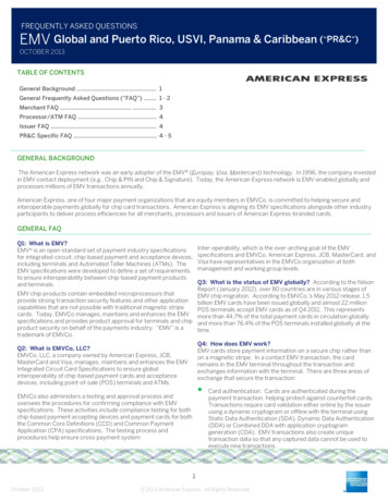
Surface Mount Multilayer Ceramic Chip Capacitors (SMD MLCCs)X5R Dielectric, 4 – 50 VDC (Commercial Grade)Table 3 – Chip Capacitor Land Pattern Design Recommendations per IPC–7351EIASizeCodeMetricSizeCode0201Density Level A:Maximum (Most)Land Protrusion (mm)Density Level B:Median (Nominal)Land Protrusion (mm)Density Level C:Minimum (Least)Land Protrusion ly for capacitance values 22 µFDensity Level A: For low-density product applications. Recommended for wave solder applications and provides a wider process window for reflowsolder processes. KEMET only recommends wave soldering of EIA 0603, 0805 and 1206 case sizes.Density Level B: For products with a moderate level of component density. Provides a robust solder attachment condition for reflow solder processes.Density Level C: For high component density product applications. Before adapting the minimum land pattern variations the user should performqualification testing based on the conditions outlined in IPC Standard 7351 (IPC–7351).1Image below based on Density Level B for an EIA 1210 case size.V1YYXXCCV2Grid Placement Courtyard KEMET Electronics Corporation P.O. Box 5928 Greenville, SC 29606 864-963-6300 www.kemet.comC1006 X5R SMD 11/15/20169
Surface Mount Multilayer Ceramic Chip Capacitors (SMD MLCCs)X5R Dielectric, 4 – 50 VDC (Commercial Grade)Soldering ProcessRecommended Soldering Technique: Solder wave or solder reflow for EIA case sizes 0603, 0805 and 1206 All other EIA case sizes are limited to solder reflow onlyRecommended Reflow Soldering Profile:KEMET’s families of surface mount multilayer ceramic capacitors (SMD MLCCs) are compatible with wave (single or dual),convection, IR or vapor phase reflow techniques. Preheating of these components is recommended to avoid extreme thermalstress. KEMET’s recommended profile conditions for convection and IR reflow reflect the profile conditions of the IPC/J-STD-020 standard for moisture sensitivity testing. These devices can safely withstand a maximum of three reflow passesat these conditions.Termination FinishSnPbTP100% Matte SnPreheat/SoakTemperature Minimum (TSmin)Temperature Maximum (TSmax)Time (tS) from TSmin to TSmax100 C150 C60 – 120 seconds150 C200 C60 – 120 secondsRamp-Up Rate (TL to TP)3 C/secondmaximum3 C/secondmaximumLiquidous Temperature (TL)183 C217 CTime Above Liquidous (tL)60 – 150 seconds60 – 150 secondsPeak Temperature (TP)235 C260 CTime Within 5 C of MaximumPeak Temperature (tP)20 secondsmaximum30 secondsmaximumRamp-Down Rate (TP to TL)6 C/secondmaximum6 C/secondmaximumTLTemperatureProfile FeaturetPMaximum Ramp Up Rate 3ºC/secMaximum Ramp Down Rate 6ºC/sectLTsmaxTsmin25ts25ºC to PeakTimeTime 25 C to Peak6 minutes8 minutesTemperaturemaximummaximumNote 1: All temperatures refer to the center of the package, measured on thecapacitor body surface that is facing up during assembly reflow. KEMET Electronics Corporation P.O. Box 5928 Greenville, SC 29606 864-963-6300 www.kemet.comC1006 X5R SMD 11/15/201610
Surface Mount Multilayer Ceramic Chip Capacitors (SMD MLCCs)X5R Dielectric, 4 – 50 VDC (Commercial Grade)Table 4 – Performance & Reliability: Test Methods and ConditionsStressReferenceTest or Inspection MethodTerminal StrengthJIS–C–6429Appendix 1, Note: Force of 1.8 kg for 60 seconds.Board FlexJIS–C–6429Appendix 2, Note: Standard termination system – 2.0 mm (minimum) for all except 3 mm forC0G. Flexible termination system – 3.0 mm (minimum).Magnification 50 X. Conditions:SolderabilityJ–STD–002a) Method B, 4 hours at 155 C, dry heat at 235 Cb) Method B at 215 C category 3c) Method D, category 3 at 260 CTemperature CyclingBiased HumidityMoisture ResistanceThermal ShockHigh Temperature LifeJESD22 Method JA–104MIL–STD–202 Method103MIL–STD–202 Method106MIL–STD–202 Method107MIL–STD–202 Method108/EIA–198Storage LifeMIL–STD–202 Method108VibrationMIL–STD–202 Method204Mechanical ShockResistance to SolventsMIL–STD–202 Method213MIL–STD–202 Method2151,000 Cycles ( 55 C to 125 C). Measurement at 24 hours / 4 hours after test conclusion.Load Humidity: 1,000 hours 85 C/85% RH and rated voltage. Add 100 K ohm resistor.Measurement at 24 hours / 4 hours after test conclusion.Low Volt Humidity: 1,000 hours 85 C/85% RH and 1.5 V. Add 100 K ohm resistor.Measurement at 24 hours / 4 hours after test conclusion.t 24 hours/cycle. Steps 7a and 7b not required.Measurement at 24 hours / 4 hours after test conclusion. 55 C/ 125 C. Note: Number of cycles required – 300. Maximum transfer time – 20seconds. Dwell time – 15 minutes. Air – Air.1,000 hours at 85 C with 2 X rated voltage applied excluding the following:Case SizeCapacitance0402 0.22 µF0603 1.0 µF0805 4.7 µF1206 2.2 µF1210 10 µFApplied Voltage1.5 X150 C, 0 VDC for 1,000 hours.5 g's for 20 minutes, 12 cycles each of 3 orientations. Note: Use 8" X 5" PCB 0.031" thick7 secure points on one long side and 2 secure points at corners of opposite sides. Partsmounted within 2" from any secure point. Test from 10 – 2,000 HzFigure 1 of Method 213, Condition F.Add aqueous wash chemical, OKEM Clean or equivalent.Storage and HandlingCeramic chip capacitors should be stored in normal working environments. While the chips themselves are quite robust inother environments, solderability will be degraded by exposure to high temperatures, high humidity, corrosive atmospheres,and long term storage. In addition, packaging materials will be degraded by high temperature–reels may soften or warpand tape peel force may increase. KEMET recommends that maximum storage temperature not exceed 40ºC and maximumstorage humidity not exceed 70% relative humidity. Temperature fluctuations should be minimized to avoid condensation onthe parts and atmospheres should be free of chlorine and sulfur bearing compounds. For optimized solderability chip stockshould be used promptly, preferably within 1.5 years of receipt. KEMET Electronics Corporation P.O. Box 5928 Greenville, SC 29606 864-963-6300 www.kemet.comC1006 X5R SMD 11/15/201611
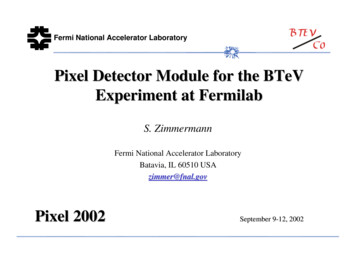
Surface Mount Multilayer Ceramic Chip Capacitors (SMD MLCCs)X5R Dielectric, 4 – 50 VDC (Commercial Grade)Construction (Typical)Detailed Cross SectionDielectric Material(BaTiO3)Barrier Layer(Ni)TerminationFinish(100% Matte Sn)DielectricMaterial (BaTiO3)End Termination/External Electrode(Cu)Inner Electrodes(Ni)End Termination/External Electrode(Cu)Barrier Layer(Ni)TerminationFinish(100% Matte Sn)Inner Electrodes(Ni) KEMET Electronics Corporation P.O. Box 5928 Greenville, SC 29606 864-963-6300 www.kemet.comC1006 X5R SMD 11/15/201612
Surface Mount Multilayer Ceramic Chip Capacitors (SMD MLCCs)X5R Dielectric, 4 – 50 VDC (Commercial Grade)Capacitor Marking (Optional):These surface mount multilayer ceramic capacitors arenormally supplied unmarked. If required, they can bemarked as an extra cost option. Marking is availableon most KEMET devices but must be requested usingthe correct ordering code identifier(s). If this option isrequested, two sides of the ceramic body will be lasermarked with a “K” to identify KEMET, followed by twocharacters (per EIA–198 - see table below) to identify thecapacitance value. EIA 0603 case size devices are limitedto the “K” character only. X7R dielectric products in capacitance values outlinedbelowMarking appears in legible contrast. Illustrated below is anexample of an MLCC with laser marking of “KA8”, whichdesignates a KEMET device with rated capacitance of 100 µF.Orientation of marking is vendor optional.KEMETIDLaser marking option is not available on: C0G, Ultra Stable X8R and Y5V dielectric devices EIA 0402 case size devices EIA 0603 case size devices with Flexible Terminationoption. KPS Commercial and Automotive Grade stacked devices.EIA Case SizeMetric Size 5160820123216322545204532456456505664 170 pF 150 pF 910 pF 2,000 pF 3,900 pF 6,700 pF 0.018 µF 0.027 µF 0.033 µF KEMET Electronics Corporation P.O. Box 5928 Greenville, SC 29606 864-963-6300 www.kemet.com2-DigitCapacitanceCodeC1006 X5R SMD 11/15/201613
Surface Mount Multilayer Ceramic Chip Capacitors (SMD MLCCs)X5R Dielectric, 4 – 50 VDC (Commercial Grade)Capacitor Marking (Optional) cont’dAlphaCharacterCapacitance (pF) For Various Alpha/Numeral IdentifiersNumeral9012345678100,000,000Capacitance 0,000,000900,000,000 KEMET Electronics Corporation P.O. Box 5928 Greenville, SC 29606 864-963-6300 www.kemet.comC1006 X5R SMD 11/15/201614
Surface Mount Multilayer Ceramic Chip Capacitors (SMD MLCCs)X5R Dielectric, 4 – 50 VDC (Commercial Grade)Tape & Reel Packaging InformationKEMET offers multilayer ceramic chip capacitors packaged in 8, 12 and 16 mm tape on 7" and 13" reels in accordance withEIA Standard 481. This packaging system is compatible with all tape-fed automatic pick and place systems. See Table 2 fordetails on reeling quantities for commercial chips.Bar Code LabelAnti-Static Reel Embossed Plastic* orPunched Paper Carrier.ETKEMChip and KPS Orientation in Pocket(except 1825 Commercial, and 1825 and 2225 Military)Sprocket HolesEmbossment or Punched Cavity8 mm, 12 mmor 16 mm Carrier Tape178 mm (7.00")or330 mm (13.00")Anti-Static Cover Tape(.10 mm (.004") Maximum Thickness)*EIA 01005, 0201, 0402 and 0603 case sizes available on punched paper carrier only.Table 5 – Carrier Tape Configuration, Embossed Plastic & Punched Paper (mm)EIA Case SizeTapeSize(W)*Embossed Plastic7" Reel13" ReelPitch (P1)*Punched Paper7" Reel13" ReelPitch (P1)*01005 – 0402822060382/42/40805844441206 – 1210844441805 – 18081244 18121288KPS 12101288KPS 1812 & 2220161212Array 0508 & 0612844*Refer to Figures 1 & 2 for W and P1 carrier tape reference locations.*Refer to Tables 6 & 7 for tolerance specifications.New 2 mm Pitch Reel Options*PackagingOrdering Code(C-Spec)Packaging Type/OptionsC-3190C-3191C-7081C-7082Automotive grade 7" reel unmarkedAutomotive grade 13" reel unmarkedCommercial grade 7" reel unmarkedCommercial grade 13" reel unmarked* 2 mm pitch reel only available for 0603 EIA case size.2 mm pitch reel for 0805 EIA case size under development.Benefits of Changing from 4 mm to 2 mm Pitching Spacing Lower placement costs Double the parts on each reel results in fewer reelchanges and increased efficiency Fewer reels result in lower packaging, shipping andstorage costs, reducing waste KEMET Electronics Corporation P.O. Box 5928 Greenville, SC 29606 864-963-6300 www.kemet.comC1006 X5R SMD 11/15/201615
Surface Mount Multilayer Ceramic Chip Capacitors (SMD MLCCs)X5R Dielectric, 4 – 50 VDC (Commercial Grade)Figure 1 – Embossed (Plastic) Carrier Tape DimensionsP2TT2ØDo[10 pitches cumulativetolerance on tape 0.2 mm]PoE1AoFKoB1E2BoS1WP1T1Center Lines of CavityØDCover TapeB 1 is for tape feeder reference only,including draft concentric about Bo.1EmbossmentFor cavity size,see Note 1 Table 4User Direction of UnreelingTable 6 – Embossed (Plastic) Carrier Tape DimensionsMetric will governConstant Dimensions — Millimeters (Inches)Tape SizeD08 mm12 mm1.5 0.10/-0.0(0.059 0.004/0.0)16 mmD1 MinimumNote 11.0(0.039)1.5(0.059)R Reference S1 MinimumTNote 2Note 3Maximum25.0(0.984)1.75 0.104.0 0.102.0 0.050.6000.600(0.069 0.004) (0.157 0.004) (0.079 0.004)Variable Dimensions — Millimeters (Inches)Tape SizePitch8 mmSingle (4 mm)12 mmSingle (4 mm) &Double (8 mm)16 mmTriple (12 mm)B1 MaximumNote 46)10.25(0.404)14.25(0.561)FP13.5 0.054.0 0.10(0.138 0.002) (0.157 0.004)5.5 0.058.0 0.10(0.217 0.002) (0.315 0.004)7.5 0.0512.0 0.10(0.138 0.002) (0.157 mum8.3(0.327)12.3(0.484)16.3(0.642)A0,B0 & K0Note 51. The embossment hole location shall be measured from the sprocket hole controlling the location of the embossment. Dimensions of embossmentlocation and hole location shall be applied independent of each other.2. The tape with or without components shall pass around R without damage (see Figure 6).3. If S1 1.0 mm, there may not be enough area for cover tape to be properly applied (see EIA Standard 481 paragraph 4.3 section b).4. B1 dimension is a reference dimension for tape feeder clearance only.5. The cavity defined by A0, B0 and K0 shall surround the component with sufficient clearance that:(a) the component does not protrude above the top surface of the carrier tape.(b) the component can be removed from the cavity in a vertical direction without mechanical restriction, after the top cover tape has been removed.(c) rotation of the component is limited to 20 maximum for 8 and 12 mm tapes and 10 maximum for 16 mm tapes (see Figure 3).(d) lateral movement of the component is restricted to 0.5 mm maximum for 8 and 12 mm wide tape and to 1.0 mm maximum for 16 mm tape (seeFigure 4).(e) for KPS Series product, A0 and B0 are measured on a plane 0.3 mm above the bottom of the pocket.(f) see Addendum in EIA Standard 481 for standards relating to more precise taping requirements. KEMET Electronics Corporation P.O. Box 5928 Greenville, SC 29606 864-963-6300 www.kemet.comC1006 X5R SMD 11/15/201616
Surface Mount Multilayer Ceramic Chip Capacitors (SMD MLCCs)X5R Dielectric, 4 – 50 VDC (Commercial Grade)Figure 2 – Punched (Paper) Carrier Tape DimensionsTPoØDo[10 pitches cumulativetolerance on tape 0.2 mm]A0FP1T1T1Top Cover TapeWE2B0Bottom Cover TapeE1GCavity Size,SeeNote 1, Table 7Center Lines of CavityBottom Cover TapeUser Direction of UnreelingTable 7 – Punched (Paper) Carrier Tape DimensionsMetric will governConstant Dimensions — Millimeters (Inches)Tape SizeD0E1P0P2T1 MaximumG Minimum8 mm1.5 0.10 -0.0(0.059 0.004 -0.0)1.75 0.10(0.069 0.004)4.0 0.10(0.157 0.004)2.0 0.05(0.079 0.002)0.10(0.004)MaximumR ReferenceNote 20.75(0.03
DWV is the voltage a capacitor can withstand (survive) for a short period of time. It exceeds the nominal and continuous working voltage of the capacitor. 3 . Capacitance and dissipation factor (DF) measured under the following conditions: 1 kHz 50 Hz and 1.0 0.2 Vrms if capacitance 10 µF