Transcription
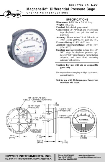
Measurements with CapacitanceGage for Sub-Nanometer ThermalExpansion CharacterizationMTI Instruments contracted an independent Metrology expert to test and verify theperformance of a new high resolution capacitance gauge. The Accumeasure HD haspassed in house testing where its performance was tested against a commercial laserinterferometer (See Application Note). Optical Metrology Solutions was chosen basedon their extensive experience and proximity to MTI’s manufacturing plant.Optical Metrology Solutions(OMS) Task:OMS was tasked with designing a challengingexperiment to verify the accuracy and resolutionof the MTI Accumeasure HD capacitance system that could also be encountered in a typicalcustomer application. The experimental setupand results are as follows:Measurements with CapacitanceGage for Sub-Nanometer ThermalExpansion CharacterizationKevin HardingOptical Metrology SolutionsEXPERIMENTAL ABSTRACTThe ability to measure small thermal expansionsof precision components can be critical to theperformance of precision instruments such asoptical telescopes. This white paper exploresthe ability of MTI’s HD capacitance gage tomeasure expansion of optical elements in thesub-nanometer range.The image on the left demonstrates what can happen toastronomical images without temperature compensationDISCUSSIONSetupTo explore the ability to measure very smallthermal expansions of a ceramic material, weused a 6-millimeter thick, optical mirror with anunprotected gold coating. Many low expansionmaterials, such as Zerodur, are well characterizedmaterials used for critical optical mirrorapplications because of their low coefficientof thermal expansion of 0.1 x 10 -6. With a 6mmthick mirror, a change of 0.1 degrees C wouldcreate a change in mirror thickness of only 60pico-meters. For a glass mirror the expansion isonly about 6 to 10 nanometers for 0.1 degree Cchange. Stability at these levels is very difficultto achieve, but in some critical applications, suchchanges may cause an optical system to blur orMTI Instruments Inc. 1-800-342-2203 sales@mtiinstruments.com1
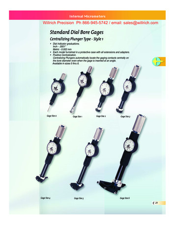
Measurements with Capacitance Gage for Sub-NanometerThermal Expansion Characterizationlose resolution. Capacitance probes have thepotential to measure such low changes over asmall measurement range. In order to explorethe ability to measure such a small change, wedeveloped a test fixture using a low expansionceramic material to hold the mirror and probewithin less than 50 microns of each other so asto be in range of the capacitance probe. The MTIcapacitance probe chosen was an ASP-50M-CTAwhich has a 50 um measuring range. The matingcapacitance amplifier is the MTI Accumeasure HDwhich is designed to have very high resolution.The probe and amplifier were linearized on an airbearing stage using a glass encoder scale with100nm accuracy.The setup is shown in FIGURE 1: The fixturestand consisted of a holder for the mirror whichsupported the mirror from the bottom leavingthe mirror free to expand upward. A similarholder supported the probe from the bottom,removing any expansion of the probe case fromthe measurement. The two support plates whereconnected with three rods made of the samevery low expansion ceramic material. The mirrorwas instrumented with three thermocouplesaround the exposed side of the mirror using heatconducting adhesive, as well as one thermistorused for feedback to a thermal electric deviceattached to the back of the mirror for heating.A ground wire needed for the operation ofthe capacitance probe was attached to thegold surface of the mirror using an electricalconducting adhesive.By providing local heating to the back of themirror and keeping the system isolated from room“breezes”, the mirror should slowly expand withlittle expansion of the ceramic support structure,permitting measurement of the mirror growthduring heating by the capacitance probe. Onlythe amount of the support structure betweenthe mirror back and the base of the probe wouldcontribute to any changes from the ceramicsupport. The thermal couple sensors monitorthe heat distribution in the mirror to verify thatuneven tilt does not occur, and also as an input tocalculating the theoretical expansion of the mirrorto compare against the reading from the probe.The system was checked in stages to verifyoperation of the various sensors. First just smallheating was applied to verify the mirror appearedto heat uniformly and that all thermocoupleswere operating consistently. The thermal coupleswere read using an Omega HH520, four channelhandheld data logger thermometer (the 4thchannel being used to monitor the air environmentsurrounding the structure). A box of 2-inch thickStyrofoam was used to isolate the whole test unitfrom room thermal variations. The heating wasdone using an Omega TE-8-0.45-1.3 thermalelectric module and TC-720 controller. An OmegaMP-3189 Thermistor was attached to the 4th or12 O’clock position (with the thermo couples at3, 6, and 9 o’clock positions) on the side of themirror for feedback to the thermo-electric controlunit. The whole system was placed on a vibrationisolated optics table using passively air isolation.ResultsAs a first simple test, the temperature of the mirrorwas raised about 1.5 degrees C then allowed to fallFIGURE 1.Mockup of the standto hold the probe andmirror (left and center)then instrumentedwith thermal couplesand thermal electricsystem (right).MTI Instruments Inc. 1-800-342-2203 sales@mtiinstruments.com2
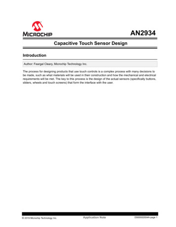
Measurements with Capacitance Gage for Sub-NanometerThermal Expansion CharacterizationFIGURE 2. Mirror Expansion vs TimeFIGURE 3. The change of the mirror thickness closelyfollows the temperature change.naturally. The heating controller uses pulse widthmodulation for regulating the heating which wasfound to introduce some noise into the stability ofthe temperature ramp. By turning off the heating,the thermal noise was minimized. A graph of themirror expansion versus time is shown in FIGURE2 and expansion versus temperature in FIGURE 3.Note: The capacitance sensor is measuring thegap from the probe to the mirror so as the mirrorcontracts with the temperature drop, the gapincreases proportionally and the gap is what isplotted here. The measured change of the mirrorsurface contains whatever the expansion factoris from the mounting structure, as well as anyexpansion of the probe tip which is very close tothe mirror surface.closely followed the temperature change in anearly linear fashion. The total displacement wasabout 90 nanometers for 1 degree C change.The effective change was about 8.9 nanometersper 0.1 degree C change. The total time of thechange was about 3 minutes. For the 6-millimeterthick mirror, this represented an effective thermalcoefficient of about 15 x 10 -6 /C, which is closeto the typical number for glass.As expected, the measured effective mirrorexpansion (contraction for temperature decrease)We attempted to make small temperature stepchanges using a dwell at each level of about15 minutes. Even at this level, the temperaturecontroller tended to oscillate (PWM modulation)in order to produce the desired temperatureintroducing noise. FIGURE 4 shows the typicaltemperature fluctuation for steps of 0.1 C.FIGURE 4.The thermal noiseis pronouncedeven with 0.1C stepchanges.MTI Instruments Inc. 1-800-342-2203 sales@mtiinstruments.com3
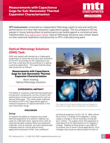
Measurements with Capacitance Gage for Sub-NanometerThermal Expansion CharacterizationFIGURE 5.Analysis of rangechanges fortemperature goingdown at 0.05 degreeC step changes.FIGURE 6. Temperaturefluctuations for controllerin oscillation.The graph and analysis of each level for a 0.05C change is shown in FIGURE 5. The standarddeviation average was around 0.16 nanometerswith a variance in the step size of 1.36 nanometers.It proved difficult to obtain steady temperaturechanges over an extended length of time. To tryto get around this limitation, the controller wasset to make a small oscillation in temperaturewhich resulted in the least thermal variationnoise. The temperature profile is shown in FIGURE6 and the resulting displacement and analysis inFIGURE 7. A least noisedata set from setting thetemperature controllerinto oscillation showconsistent steps andnoise levels on averagearound 60 picometers,representing the noiselevel of the sensor.MTI Instruments Inc. 1-800-342-2203 sales@mtiinstruments.com4
Measurements with Capacitance Gage for Sub-NanometerThermal Expansion CharacterizationFIGURE 8.Temperature Oscillations 0ver0.04 degree C simulatinginstrument stability test.Step Oscillations over 0.04CFIGURE 9.Effective Optical elementthickness variations due totemperature changes with anaverage 1 sigma value of 66picometers. The thicknesschange is clearly measurable.FIGURE 7. This minimum temperature controllernoise situation suggests a noise floor for the sensorof around 60 picometers with step sizes under ananometer clearly measurable with good signal tonoise ratio.A second set of oscillations over 0.04 degreesare shown in FIGURE 8 AND 9. This level ofsensitivity would be typical of what might beneeded to characterize optical elements for aprecision instrument such as might be used inaerospace applications.The average standard deviation of about 69picometers is consistent with previous runs. Thisnumber represents the lower limit on what rangechanges could be detected by the sensor, withclearly resolvable changes available in the 300picometer range.ConclusionsThese results conclusively demonstrate thecapability of the MTI capacitance HD amplifier, anda 50um range probe to measure the very smallMTI Instruments Inc. 1-800-342-2203 sales@mtiinstruments.com5
Measurements with Capacitance Gage for Sub-NanometerThermal Expansion Characterizationdistance changes (pico- meters) encountered in apractical application where thickness changes arecaused by thermal variation of precision opticalelements. The ability to measure such changes atthis pico-meter level is difficult to realize with mostother metrology tools except at high expensesuch as a laser interferometer. Additionally,the capacitive measurements correlated to theexpected mirror changes as computed from thenormal thermal coefficients of expansions ofthe test materials used in this experiment furtherverifying the results.Some of Optical Metrology Solutionsqualifications:Kevin Harding: PresidentAbout Kevin Harding: 39 years of experiencein optics, vision, metrology; editor and primaryauthor of the CRC Handbook of OpticalDimensional Metrology; member of the Societyof Photo-Optical Instrumentation Engineers(SPIE) for 30 years (fellow, instructor, and pastpresident), recipient of the President’s Award fromSPIE; SME Young Engineer & Eli Whitney Award;Sr. Member, MVA Chair, AIA Leadership Award,Engineering Society of Detroit Leadership Authorwith more than 150 papers, 5 book chapters,and over 80 patents in optics/metrology; morethan 80 Tutorials taught, Optics and Lighting forMachine Vision, Metrology, Optics for Non-OpticsPeople; 3D Optical Metrology Expertise; QualitySystems, six sigma methods, Optical SystemDesign, Machine Vision System Development,Analysis Optical Metrology ApplicationEngineering/ Technology/Market Evaluations;Deep technical knowledge commercial (and non)optical gages (1- 2-3D) Extensive Governmentand Industry proposal and contract experience.Work Experience Includes: University of DaytonResearch Institute, Industrial Technology Institute(Director: Cost, Quality, Productivity), GE GlobalResearch (Principal Engineer).Robert Tait: PartnerAbout Robert Tait: Over 37 years of experience inVision, Automation; Frequent Speaker; Instructor:Vision Show, Automate, NI Week Workedwith several company startups (electronicsinspection) Expertise: Machine Vision System/Automation Integration, Lab View Programming,Automation Control Lighting/Imaging/controlsintegration/Shop hardening, CollaborativeRobots. Work Experience includes: University ofDayton Research Institute (at WPAFB), IndustrialTechnology Institute, Intelligent ReasoningSystems Inc, Dimension Data, GE Global Research.AfterwordMTI would like to thank Optical MetrologySolutions for their hard work in creating andcarrying out this experiment. It was gratifying tosee OMS reached a similar conclusion from MTI’sexperimental verification when testing piezostage displacements down to pico-meter levels.(Reference: MTI’s Accumeasure HD Amplifier vs.SmarAct’s PicoScale Interferometer)About the MTI InstrumentsAccumeasure D200HDThe MTI Instruments Accumeasure D200HD isa two-channel, picometer scale, capacitancebased, displacement measurement instrumentfor conductive targets. The D200HD achievesvery high resolution with the aid of externalpreamplifiers that are located close to the probesthat eliminate parasitic capacitance effectswhich cause noise. Digital communication isprovided via Ethernet or USB. The bandwidthand range extension of the probes are digitallyprogrammable. Resolutions as low as 20pm maybe achieved with a 10um range probe. Visitour site to see more details on the AccumeasureD200HD.MTI Instruments Inc. 1-800-342-2203 sales@mtiinstruments.com6
developed a test fixture using a low expansion ceramic material to hold the mirror and probe within less than 50 microns of each other so as to be in range of the capacitance probe. The MTI capacitance probe chosen was an ASP-50M-CTA which has a 50 um measuring range. The mating capacitance amplifier is the MTI Accumeasure HD