Transcription
PROGRAMMING WORKBOOKHAAS AUTOMATION, INC.2800 Sturgis Rd.Oxnard, CA 93030JUNE 1, 2000
JUNE 2000PROGRAMMINGCONTENTSINTRODUCTION . 1THE COORDINATE SYSTEM . 2MACHINE HOME . 5ABSOLUTE AND INCREMENTAL POSITIONING . 5POSITIONING EXERCISE . 7PROGRAMMING WITH CODES . 8PROGRAM STRUCTURE . 9PROGRAM FORMAT . 13MISCELLANEOUS FUNCTIONS (M CODES) . 16PREPARATORY FUNCTIONS (G CODES) . 18MACHINE DEFAULTS . 22LIST OF CANNED CYCLES . 23ALPHABETICAL ADDRESS CODES . 24RAPID POSITION COMMANDS (G00). 28INTERPOLATION COMMANDS (G01). 29CIRCULAR INTERPOLATION COMMANDS (G02,G03) . 30INTERPOLATION EXERCISE. 39PROGRAM START-UP LINES . 40PROGRAM ENDING LINES . 41DWELL (G04) . 42CIRCULAR POCKET MILLING (G12, G13) . 43CIRCULAR POCKET MILLING EXERCISE . 46CIRCULAR PLANE SELECTION (G17, G18, G19) . 47INCH / METRIC SELECTION (G20, G21) . 51REFERENCE POINT DEFINITION AND RETURN (G28) . 52CUTTER COMPENSATION (G40, G41, G42) . 53CUTTER COMPENSATION EXERCISE #1 . 59CUTTER COMPENSATION EXERCISE #2 . 62HELICAL MOTION . 64TOOL LENGTH COMPENSATION (G43) . 66WORK COORDINATE SELECTION (G54-59, G110-129, G52, G53, G92). 67NON-MODAL COORDINATE SELECTION (G53) . 67ANOTHER WAY TO SEND MACHINE HOME USING G53 SELECTION . 68CANNED CYCLES DESCRIPTION . 69CANCEL - CANNED CYCLE (G80) . 70DRILL - CANNED CYCLE (G81) . 71SPOT DRILL - CANNED CYCLE (G82) . 72
JUNE 2000PROGRAMMINGCONTENTSDEEP HOLE PECK DRILLING CANNED CYCLE (G83) . 73CANNED CYCLE EXERCISE #1 . 76TAPPING - CANNED CYCLE (G84) . 78BORE IN - BORE OUT - CANNED CYCLE (G85) . 79BORE IN - STOP - RAPID OUT - CANNED CYCLE (G86) . 80BORE IN - MANUAL RETRACT - CANNED CYCLE (G87) . 81BORE IN - DWELL - MANUAL RETRACT - CANNED CYCLE (G88) . 82BORE IN - DWELL - BORE OUT - CANNED CYCLE (G89) . 83CANNED CYCLE EXERCISE #2 . 84HIGH SPEED PECK DRILL - CANNED CYCLE (G73) . 86REVERSE TAPPING - CANNED CYCLE (G74) . 90FINE BORING - CANNED CYCLE (G76) . 91BACK BORE - CANNED CANNED CYCLE (G77) . 92CANNED CYCLE RETURN PLANES (G98, G99) . 93CANNED CYCLES BOLT HOLE PATTERNS (G70, G71, G72) . 94CANNED CYCLES BOLT HOLE PATTERN (G70) . 95CANNED CYCLES BOLT HOLE PATTERN (G71) . 96CANNED CYCLES BOLT HOLE PATTERN (G72) . 97CANNED CYCLE EXERCISE #3 . 98SUBROUTINES (M97, M98, M99) . 100GENERAL PURPOSE POCKET MILLING (G150) . 103FINAL EXERCISE . 108
JUNE 2000PROGRAMMINGINTRODUCTIONThis manual provides basic programming principles necessary to begin programming the HAAS C.N.C. Milling Machine.In a CNC (Computerized Numerical Control) machine, the tool is controlled by acomputer and is programmed with a machine code system that enables it to beoperated with minimal supervision and with a great deal of repeatability.The same principles used in operating a manual machine are used in programminga CNC machine. The main difference is that instead of cranking handles to positiona slide to a certain point, the dimension is stored in the memory of the machinecontrol once. The control will then move the machine to these positions each timethe program is run.In order to operate and program a CNC controlled machine, a basic understandingof machining practices and a working knowledge of math is necessary. It is alsoimportant to become familiar with the control console and the placement of the keys,switches, displays, etc., that are pertinent to the operation of the machine.This workbook can be used for both operator s and programmer s. It is intended togive a basic understanding of CNC programming and it s applications. It is notintended as an in-depth study of all ranges of machine use, but as an overview ofcommon and potential situations facing CNC programmers. Much more trainingand information is necessary before attempting to program on the machine.This programming manual is meant as a supplementary teaching aid to users of theHAAS Mill. The information in this workbook may apply in whole or in part to theoperation of other CNC machines. Its use is intended only as an aid in the operationof the HAAS Milling Machine. For a complete explanation and an in-depth description, refer to the Programming and Operation Manual that is supplied with yourHAAS Lathe.1
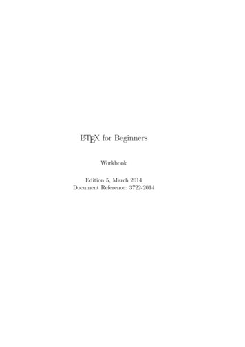
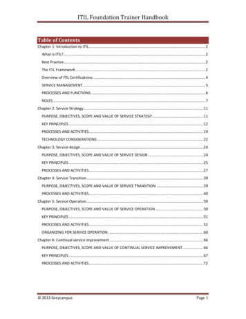
PROGRAMMINGJUNE 2000THE COORDINATE SYSTEMThe first diagram we are concerned with is called a NUMBER LINE. This numberline has a zero reference point that is calledan ABSOLUTE ZERO and may be placed atany point along the number line.Horizontal number lineThe number line also has numbered increments on either side of absolutezero. Moving away from zero to the right are positive increments. Movingaway from zero to the left are negative increments. The , or positiveincrements, are understood, therefore no sign is needed. We use positiveand negative signs along with increment value's to indicate its relationshipto zero on the line. If we choose to move to the third increment on the minus(-) side of zero, we would call for -3. If we choose the second increment inthe plus range, we would call for 2. Our concern is the distance and thedirection from zero.Remember that zero may be placed at any point along the line, and thatonce placed, one side of zero has negative increments and the other sidehas positive increments.Vertical number lineThe machine illustration shows threedirections of travel available on a vertical machine center. To carry the number line idea a little further, imaginesuch a line placed along each axis ofthe machine. It shows the three directions to position the coordinatesaround a part origin, which is wherethese number lines intersect on a vertical machining center with the X, Y,and Z axis lines.The first number line is easy to conceive as belonging to the left-to-right,or X , axis of the machine. If weplace a similar number line along thefront-to-back, or Y axis, the increments (not the table) toward the operator, from Y zero, are the negativeincrements. The increments on theother side of zero away from the operator are positive increments.2
JUNE 2000PROGRAMMINGThe third axis of travel on our machine is the up-and-down, or Z axis. When weplace a number line on the Z travel, the positive increments are up above zero, andthe negative values are down below zero. The increments of each number line onHAAS machining centers equals .0001 inches. Also, while a line theoreticallytravels infinitely in either direction once established, the three lines placed alongthe X, Y, and Z axes of the machine do not have unlimited accessibility. That is tosay, we are limited by the range of travel on the model of machining center.MACHINEX-axis travelY-axis travelZ-axis travelVF-E / VF-0 / VF120"16"20"VF-EXT / 0"HS-1/1R/1RP24"20"22"HS-2RP38"35"30"Remember, when we are moving the machine, we are concerned with positioningthe center of the spindle in relation to X,Y and Z zero. Although the machine tableis the moving part, we have to keep in mind our coordinates are based off ourtheoretical spindle movement.Keep in mind that the part zero position may be defined at any point along each ofthe three axes, and will usually be different for each setup of the machine.It is noteworthy to mention here that the Z-axis is set with the machine zero positionin the upward position, or the tool change position. This will place most all Z movesin a negative range of travel.3v
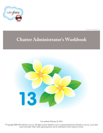
PROGRAMMINGJUNE 2000Fig. 1-4 view shows the X,Y work zero grid from above. The work part zero for theZ-axis is usually set at the top of the part surface, and this will be entered in the toollength offset as a negative value for each tool. The range of Z-axis travel on theHAAS VF-1, for example, is 20 inches total; four of these inches are above toolchange position and is listed as a positive tool length offset, and 16 inches arebelow tool change position and listed as a negative. The diagram shows a top viewof the grid as it would appear on the machine tool. This view shows the X and Y axesas the operator faces a vertical machine table. Note that at the intersection of thetwo lines, a common zero point is established. Thefour areas on each side and above and below thelines are called QUADRANTS and make up thebasis for what is known as rectangular RANT1 IS ON THE TOP RIGHT X Y 2 IS ON THE TOP LEFT X- Y 3 IS ON THE BOTTOM LEFT X- Y4 IS ON THE BOTTOM RIGHT X Y-Whenever we set a zero point somewhere on the Xaxis and, a zero point somewhere on the Y-axis, wehave automatically set a work zero point and anintersection of the two number lines. This intersection where the two zeros come together will automatically have the four quadrants to its sides, above,and below it. How much of a quadrant we will beable to access is determined by where we place the zero point within the travel ofthe machine axes. For example, for a VF-1, if we set zero exactly in the middle ofthe travel of X and Y (table center), we have created four quadrants that are 10inches by 8 inches in size.4
JUNE 2000PROGRAMMINGMACHINE HOMEWhen a zero return (ZERO RET) is performed at machine start up, all three axes aremoved to extreme positive locations until limit switches are reached. When thiscondition is satisfied, the only way to move any of the three axes is in the negativedirection (except for a positive four inches in Z-axis). Thisis because this position is defined as your MACHINEHOME for each of the three axes automatically when themachine was sent home with the POWER-UP/RESTARTkey. In effect, now the positive quadrants cannot be reachedfrom machine home position in X and Y axes, and all themoves will be found to be in the X-, Y- quadrant. It is onlyby setting a new part zero somewhere within the travel ofeach axes that other quadrants are able to be reached.Sometimes it is useful in the machining of a part to utilizemore than one of these X,Y quadrants. An example of thisAll four quadrants will haveis a round part that has it s datum lines running through theto be accessed to positionaround this part XY zero point.center. The setup of such a part may need machining to beperformed in all four quadrants of a part. This is why youwould want to make use of all four quadrants of the X and Y axes on a millingmachine. As you gain more experience in machine tool programming and of setuptechniques, you'll have a better understanding of how to position your machine tooland how to define a part zero origin and how to position a tool around that origin .ABSOLUTE AND INCREMENTAL POSITIONINGUp to this point, we have dealt with a system of positioning the tool that is known asabsolute programming. In absolute, all coordinate positions are given with regardto their relationship to a fix
This programming manual is meant as a supplementary teaching aid to users of the HAAS Mill. The information in this workbook may apply in whole or in part to the operation of other CNC machines. Its use is intended only as an aid in the operation of the HAAS Milling Machine. For a complete explanation and an in-depth descrip-