Transcription
UDS2100Device Server User GuidePart Number 900-448Revision J February 2020
Intellectual Property 2020 Lantronix. All rights reserved. No part of the contents of this book may betransmitted or reproduced in any form or by any means without the written permission ofLantronix.Lantronix is a registered trademark and DeviceInstaller is a trademark of Lantronix, Inc.in the United States and other countries.Patented: http://patents.lantronix.com; additional patents pending.Windows and Internet Explorer are registered trademarks of Microsoft Corporation.Mozilla and Firefox are registered trademarks of the Mozilla Foundation. Chrome is atrademark of Google. Opera is a trademark of Opera Software ASA. All othertrademarks and trade names are the property of their respective holders.WarrantyFor details on the Lantronix warranty policy, please go to our Web site onix7535 Irvine Center DriveSuite 100Irvine, CA 92618, USAToll Free: nical SupportOnline: www.lantronix.com/supportSales OfficesFor a current list of our domestic and international sales offices, go to the Lantronix website at www.lantronix.com/about/contact.DisclaimerAll information contained herein is provided “AS IS.” Lantronix undertakes no obligationto update the information in this publication. Lantronix does not make, and specificallydisclaims, all warranties of any kind (express, implied or otherwise) regarding title, noninfringement, fitness, quality, accuracy, completeness, usefulness, suitability orperformance of the information provided herein. Lantronix shall have no liabilitywhatsoever to any user for any damages, losses and causes of action (whether incontract or in tort or otherwise) in connection with the user’s access or usage of any ofthe information or content contained herein. The information and specificationscontained in this document are subject to change without notice.UDS2100 Device Server User Guide2
Operation of this equipment in a residential area is likely to cause interference, in whichcase the user, at his or her own expense, will be required to take whatever measuresmay be required to correct the interference.See the compliance section of this document for more information on conformance tointernational standards.Revision HistoryDateSeptember 2006Rev. CommentsAInitial documentMay 2007BUpdated to reflect firmware version 6.5.0.0, including UDP Broadcast; added twomore Monitor Mode commands and diagrams of mounting brackets.August 2008CUpdated for firmware version 6.6.0.0.January 2009DReference to documentation on Lantronix website; minor correctionsOctober 2012EUpdated for firmware version 6.8.0.0.June 2015FUpdated for firmware version 6.11.0.0.December 2017GUpdated enhanced password information.October 2018HUpdated disclaimer, product label description, technical specifications, andcompliance section.February 2020JUpdated for firmware version 7.0.0.1. Updated with new default password andsecurity information.UDS2100 Device Server User Guide3
Table of ContentsIntellectual Property 2Warranty 2Contacts 2Disclaimer 2Revision History 3List of Figures 8List of Tables 81: Using This Guide9Purpose and Audience 9Chapter Summary 9Additional Documentation 102: Introduction11Applications 11Application Examples 11Protocol Support 13Additional Features 13Configuration Methods 13Product Information Label 143: Installation of UDS210015Package Contents 15Installing the UDS 15Required Information 16Hardware Address 16IP Address 164: Using DeviceInstaller18Installing DeviceInstaller 18Assigning an IP Address 18Adding the Unit to the Manage List 19Accessing the UDS2100 Using DeviceInstaller 19Viewing the Current Configuration 20Next Step 22Assigning the IP Address: Serial Port Login 225: Configuration Using Web Manager23Accessing UDS2100 Using DeviceInstaller 23Network Configuration 25Network Mode 25Automatic IP Address Configuration 25Static IP Address Configuration 26Ethernet Configuration 27Server Configuration 27UDS2100 Device Server User Guide4
Table of ContentsHost List Configuration 29Channel 1 and Channel 2 Configuration 30Serial Settings 30Connection Settings - TCP 33Connection Settings - UDP 36Apply Settings 37Apply Defaults 376: Configuration via Telnet or Serial Port (Setup Mode)38Accessing Setup Mode 38Telnet Connection 38Serial Port Connection 39Exiting Setup Mode 407: Setup Mode: Server Configuration41Server Configuration (Option 0) 41IP Address 41Set Gateway IP Address 41Netmask: Number of Bits for Host Part 42Set DNS Server IP Address 42Change Telnet/Web Configuration Password 42DHCP Name 43Enable DHCP FQDN Option 438: Setup Mode: Channel Configuration44Channel 1 (Option 1) 44Baudrate 44I/F (Interface) Mode 45Flow 45Port Number 46Connect Mode 46Send the Escape Sequence ( ) in Modem Mode 54Show IP addr after 'RING' 54Auto Increment Source Port 54Remote IP Address 54Remote Port 54DisConnMode 54Flush Mode (Buffer Flushing) 55Pack Control 56Packing Interval 57Trailing Characters 57Send Characters 57DisConnTime (Inactivity Timeout) 57Send Characters 57UDS2100 Device Server User Guide5
Table of ContentsTelnet Terminal Type 58Channel (Port) Password 589: Setup Mode: Advanced Settings59Expert Settings (Option 5) 59TCP Keepalive Time In Seconds 59ARP Cache Timeout In Seconds 59CPU Performance 59Disable Monitor Mode at Bootup 60HTTP Port Number 60MTU Size 60TCP Re-Transmission Timeout 60Enable Alternate MAC 60Ethernet Connection Type 60Security Settings (Option 6) 61Disable SNMP 61SNMP Community Name 61Disable Telnet Setup 61Disable TFTP Firmware Update 62Disable Port 77FE (Hex) 6277FEh Access Mode 62Disable Web Server 62Disable Web Setup 63Disable ECHO Ports 63Enable Enhanced Password 63Default Settings (Option 7) 63Channel 1 & 2 Configuration Defaults 63Expert Settings Defaults 64Security Settings Defaults 6410: Firmware Upgrades65Obtaining Firmware 65Reloading Firmware 65Using TFTP: Graphical User Interface 65Using TFTP: Command Line Interface 66Recovering the Firmware Using the Serial Port and DeviceInstaller 6611: Monitor Mode68Entering Monitor Mode Using the Serial Port 68Entering Monitor Mode Using the Network Port 68Monitor Mode Commands 68A: Troubleshooting and Contact Information71LEDs 71Problems and Error Messages 73UDS2100 Device Server User Guide6
Table of ContentsLantronix Technical Support 75B: Connections and Pinouts76Serial Port 76Serial Connector Pinouts 76Modem Cable 77Network Port 77Reset Button 77Ethernet Connector Pinouts 78Power Plug 78C: Technical Specifications79D: Mounting Brackets81E: Alternative Ways to Assign an IP Address82DHCP 82AutoIP 82BOOTP 83ARP and Telnet 83F: Binary to Hexadecimal Conversions84Converting Binary to Hexadecimal 84Conversion Table 84Scientific Calculator 85G: Compliance86RoHS, REACH and WEEE Compliance Statement 90IndexUDS2100 Device Server User Guide917
List of FiguresFigure 2-1. Serial Tunneling ExampleFigure 2-2. Direct TCP/IP or Redirector ConfigurationFigure 2-3. Product Label with QR CodeFigure 2-4. Product LabelFigure 3-1. UDS2100 Connected to Serial Device and NetworkFigure 5-1. Web Manager Login WindowFigure 5-2. Lantronix Web ManagerFigure 5-3. Network SettingsFigure 5-4. Server SettingsFigure 5-5. Hostlist SettingsFigure 5-6. Channel Serial SettingsFigure 5-7. TCP Connection SettingsFigure 5-8. UDP Connection SettingsFigure 5-9. Apply Settings and Apply DefaultsFigure 6-1. MAC AddressFigure 6-2. Setup Menu OptionsFigure 7-1. Network SettingsFigure 8-1. Serial Port SettingsFigure 8-2. Interface ModeFigure 8-3. Hostlist OptionFigure 9-1. Expert SettingsFigure 9-2. Security SettingsFigure 10-1. TFTP WindowFigure A-11-1. Diagnostic, Power, and Serial Port LEDsFigure B-11-2. Serial InterfaceFigure B-11-3. DB9 Male RS232 Serial DTE 96166727676List of TablesTable 7-1. BootP/DHCP/AutoIP optionsTable 7-2. Standard IP Network NetmasksTable 8-1. Interface Mode OptionsTable 8-2. Common Interface Mode SettingsTable 8-3. Flow Control OptionsTable 8-4. Reserved Port NumbersTable 8-5. Connect Mode OptionsTable 8-6. Manual Connection Address ExampleTable 8-7. Modem Mode MessagesTable 8-8. Modem Mode CommandsTable 8-9. Disconnect Mode OptionsTable 8-10. Flush Mode OptionsTable 8-11. Pack Control OptionsTable 10-1. Firmware FilesTable 11-1. Monitor Mode CommandsTable 11-2. Command Response CodesTable A-1. UDS2100 LEDsTable A-2. Problems and Error MessagesTable C-1. UDS2100 Technical SpecificationsTable G-1: Europe – EU Declaration of ConformityUDS2100 Device Server User Guide41424545464647495253555656656970727379898
1: Using This GuidePurpose and AudienceThis guide provides the information needed to configure, use, and update theUDS2100 device server. It is for system administrators and those responsible forinstalling and maintaining the UDS.Chapter SummaryThe remaining chapters in this guide include:ChapterDescription2: IntroductionDescribes the main features of the UDS and the protocols itsupports.3: Installation of UDS2100Provides information for installing your unit and getting it up andrunning using DeviceInstaller or a serial port connection.4: Using DeviceInstallerInstructions for viewing the current configuration usingDeviceInstaller.5: Configuration Using WebManagerDetails using the Web Manager to set parameters such as portand server properties.6: Configuration via Telnet orSerial Port (Setup ModeProvides instructions for accessing Setup Mode (command lineinterface) using a Telnet connection through the network or aterminal or terminal emulation program through the serial port.7: Setup Mode: ServerConfigurationDetails the network (server) settings8: Setup Mode: ChannelConfigurationDetails the serial port settings.9: Setup Mode: AdvancedSettingsDetails expert and security settings and explains how to reset theunit to factory default values.10: Firmware UpgradesProvides instructions for obtaining the latest firmware and updatingthe UDS.11: Monitor ModeProvides instructions for accessing and using the command lineinterface to monitor the network and diagnose problems.A: Troubleshooting andContact InformationDescribes common problems and error messages and how tocontact Lantronix Technical Support.B: Connections and PinoutsProvides descriptions and illustrations of connection hardware.C:Technical SpecificationsLists technical specifications for the UDS.D: Mounting BracketsProvides drawings and dimensions of the unit's mounting brackets.UDS2100 Device Server User Guide9
1: Using This GuideChapterDescriptionE: Alternative Ways to Assign Provides detailed information about using DHCP, AutoIP, BOOTPan IP AddressARP, and Telnet to assign an IP address.F: Binary to HexadecimalConversionsProvides instructions for converting binary values to hexadecimals.G: ComplianceProvides Lantronix compliance information.Additional DocumentationVisit the Lantronix Web site at www.lantronix.com/support/documentation for thelatest documentation and the following additional documentation.DocumentDescriptionUDS2100 Quick StartProvides the steps for getting the UDS2100 up and running.DeviceInstaller OnlineHelpProvides instructions for using the Windows-based utility toconfigure the UDS2100 and other Lantronix device servers.“Live” Tutorials on theLantronix Web Site(English)Explain and demonstrate assigning an IP address to the UDS andsetting up the UDS and Com Port Redirector. Seehttp://ltxfaq.custhelp.com/app/answers/detail/a id/1119.Com Port RedirectorUser GuideProvides information on using the Windows-based utility to createa virtual com port.UDS2100 Device Server User Guide10
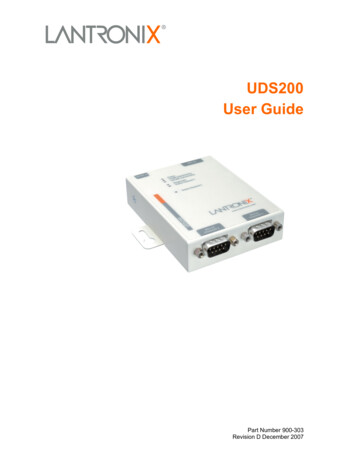
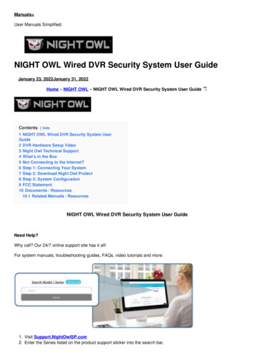
2: IntroductionThe UDS2100 is a 2-port device server that provides a quick, simple, and costeffective way to bring the advantages of data accessibility and remotemanagement to devices not currently connected to a network.ApplicationsThe UDS family of Device Servers allows serial devices, such as those listedbelow, to connect and communicate over Ethernet networks using the IP protocolfamily (TCP for connection-oriented stream applications and UDP for datagramapplications). Security alarms Access control devices Fire control panels Time/attendance clocks and terminals ATM machines Data collection devices RFID readers Universal Power Supply (UPS) management units Telecommunications equipment Data display devices Virtually any asynchronous RS-232, RS422, or RS485 deviceApplication ExamplesUsing a method called serial tunneling, the UDS encapsulates serial data intopackets and transports them over Ethernet. Using two UDS units, connected by anetwork, virtual serial connections can extend across a facility or around theworld.UDS2100 Device Server User Guide11
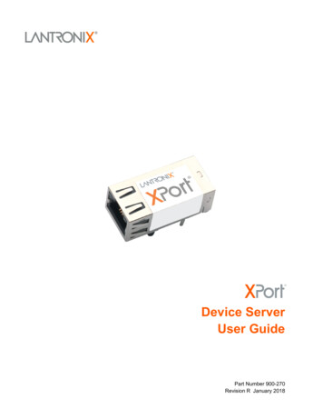
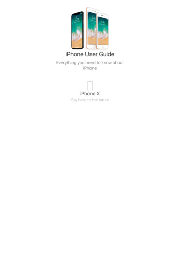
2: IntroductionFigure 2-1. Serial Tunneling ExampleThe Com Port Redirector software available for download atwww.lantronix.com/support/downloads simplifies the integration process byextending the functionality of COM-port-based Windows applications. VirtualCOM ports, mapped to remote device servers on the network, can replace directserial connections.Figure 2-2. Direct TCP/IP or Redirector ConfigurationNote: For step-by-step instructions on configuring the UDS for serial tunneling or for usewith the Com Port Redirector, see UDS Configuration Tutorials on the Lantronix web site:www.lantronix.com/support.UDS2100 Device Server User Guide12
2: IntroductionProtocol SupportThe UDS uses the Internet Protocol (IP) for network communications and theTransmission Control Protocol (TCP) to assure that no data is lost or duplicatedand that everything sent to the connection arrives correctly at the target.Supported protocols include: ARP, UDP, TCP/, BOOTP, ICMP, Telnet, TFTP, AutoIP, DHCP, HTTP, andSNMP for network communications. TCP, UDP, and Telnet for connections to the serial port. TFTP for firmware updates. IP for addressing, routing, and data block handling over the network. User Datagram Protocol (UDP) for typical datagram applications in whichdevices interact with other devices without a point-to-point connection.Additional FeaturesModem Emulation: In modem emulation mode, the UDS can replace dial-upmodems. The unit accepts modem AT commands on the serial port and thenestablishes a network connection to the end device. This arrangement leveragesnetwork connections and bandwidth to eliminate dedicated modems and phonelines.Built-in Web Server: The UDS includes a built-in web server for configuring theunit and displaying operating and troubleshooting information on the attachedlinks to online support.Configuration MethodsAfter installation, the UDS requires configuration. For the unit to operate correctlyon a network, it must have a unique IP address on the network. There are threebasic methods for logging into the UDS and assigning IP addresses and otherconfigurable settings:DeviceInstaller: Configure the IP address and other network settings on theUDS using a Graphical User Interface (GUI) on a PC attached to a network.(See 4: Using DeviceInstaller.)Web Manager: Through a web browser, configure the UDS settings using theLantronix Web Manager. (See 5: Configuration Using Web Manager.)Serial and Telnet Ports: Use Setup Mode, a command line interface. There aretwo approaches to accessing Setup Mode: making a Telnet connection to thenetwork port (9999) or connecting a terminal (or a PC running a terminalemulation program) to the unit’s serial port. See 6: Configuration via Telnet orSerial Port (Setup Mode).UDS2100 Device Server User Guide13
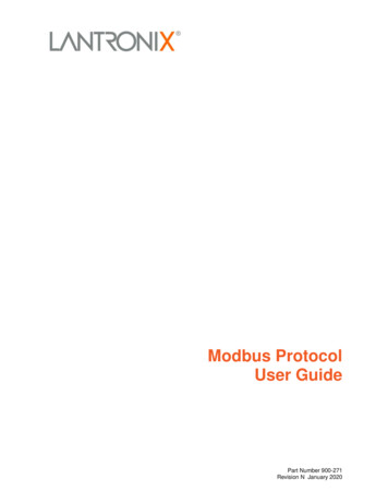
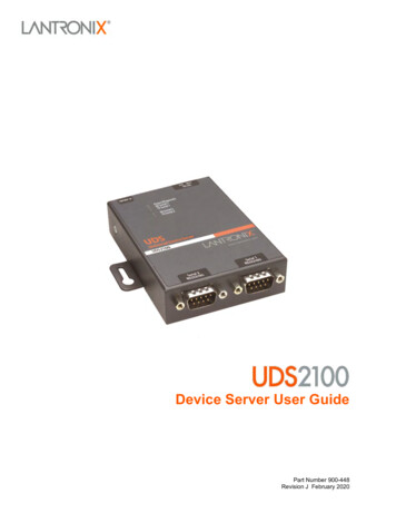
2: IntroductionProduct Information LabelThe product information label on the underside of the unit contains the followinginformation about your specific unit: QR code or bar code Part number Revision Country of manufacture Manufacturing date code Serial number (also the hardware address or MAC address) Device IDFigure 2-3. Product Label with QR CodePart NumberRevisionCountry ofManufactureManufacturingDate CodeSerial NumberDevice IDQR CodeFigure 2-4. Product Label with Bar CodeBar CodePart NumberSerial NumberUDS2100 Device Server User GuideManufacturingDate CodeRevision14
3: Installation of UDS2100This chapter describes how to install your UDS2100 and get it up and running inthe shortest possible time.Package ContentsVerify and inspect the contents of the UDS2100 package using the following list.If any item is missing or damaged, contact your place of purchase immediately. UDS2100 DB9F-to-DB9F Null Modem Cable (P/N 500-164-R) Power Supply Quick Start GuideInstalling the UDSFigure 3-1. UDS2100 Connected to Serial Device and NetworkTo install the unit:UDS2100 Device Server User Guide15
3: Installation of UDS2100To install the unit, complete the following steps in order. Refer to the numbers inthe previous figure.1. Connect a serial device to your unit. See 2: Introduction for more informationabout what kinds of device attachments the unit supports.2. Connect an Ethernet cable to the 10/100 port.3. Supply power to your unit using the power supply that was included in thepackaging.Note: The required input voltage is 9-30 VDC (center ) (1.8W maximumpower).4. Supply power to the serial device.Note: If you encounter a problem, please see A: Troubleshooting andContact Information.Required InformationBefore configuring the UDS, have the following information available:Hardware AddressTake note of the unit’s hardware address (also known as the Ethernet or MACaddress). It is on the product label (see Product Information Label).Hardware Address: 00 – 20 - 4a - - -OrHardware Address: 00 - 80 - A3 - - -Note: Make note of the MAC address. It is needed to locate the UDS2100module using DeviceInstaller.IP AddressThe UDS must have a unique IP address on your network. This addressreferences the specific unit. By default, the unit is DHCP-enabled andautomatically assigned an IP address on DHCP-enabled networks. If you areassigning a static IP address, the systems administrator generally provides the IPaddress, subnet mask, and gateway.Note: The factory default IP address is 0.0.0.0 to enable DHCP, BOOTP,and AutoIP. When the units boots, it sends a DHCP broadcast to try andget an IP address. If it receives no reply from a DHCP server, the UDStries BOOTP. If the UDS does not receive a response from BOOTP, itreverts to an AutoIP address.UDS2100 Device Server User Guide16
3: Installation of UDS2100IP Address:- - -Subnet Mask: - - -Gateway:- - -You have several options for assigning an IP address and related networksettings to your unit. This chapter provides information about using theDeviceInstaller (graphical user interface) and serial port login (command lineinterface) methods.Note: For information about other methods of assigning the IP address,such as DHCP, AutoIP, ARP, and Telnet, see E: Alternative Ways toAssign an IP Address.UDS2100 Device Server User Guide17
4: Using DeviceInstallerThis chapter covers the steps for getting the UDS2100 device server online andfor viewing its current configuration.Note: DeviceInstaller is a free utility program provided by Lantronix thatdiscovers, configures, upgrades, and manages Lantronix Device Servers.It can be downloaded from the Lantronix website atwww.lantronix.com/support/downloads.For instructions on using DeviceInstaller to configure the IP address andrelated settings or for more advanced features, see the DeviceInstallerOnline Help.By default, the username is left blank and the password is the last 8characters of the Device ID (for devices manufactured after January 1,2020) or is left blank (for all older devices).Installing DeviceInstallerTo install DeviceInstaller:1. Download the latest version of DeviceInstaller fromhttp://www.lantronix.com/support/downloads.2. Run the executable to start the installation process.3. Respond to the installation wizard prompts. (If prompted to select aninstallation type, select Typical).Assigning an IP AddressThe unit’s IP address must be configured before it can work correctly on anetwork. The unit’s IP address is normally set to 0.0.0.0 at the factory. Thehardware address is on the product label. The unit is DHCP enabled as thedefault.To assign an IP address manually:1. Click Start Programs Lantronix DeviceInstaller 4.4 DeviceInstaller. If your PC has more than one network adapter, a messagedisplays. Select an adapter and click OK.Note: If the unit already has an IP address (e.g., DHCP has assignedan IP address), click the Search iconand select the unit from thelist of Lantronix device servers on the local network.UDS2100 Device Server User Guide18
4: Using DeviceInstaller2. Click Tools Enter Global Credentials. Select Prompt with a dialog boxto login and click OK.3. Note the IP address. You can put the IP address in the address bar of abrowser to access Web Manager and proceed to assign an IP address in thenetwork settings. See Network Configuration for more information.Alternatively, continue with these steps.4. Click the Assign IP icon.5. If prompted, enter the hardware address (on the product label) and clickNext.6. Select Assign a specific IP address and click Next.7. Enter the IP address. The Subnet mask displays automatically based on theIP address; if desired, you may change it. On a local network, you can leavethe Default gateway blank (all zeros). Click Next.8. Click the Assign button and wait several seconds until a confirmationmessage displays. Click Finish.9. Select the device from the main window list and select Ping from the Toolsmenu. The Ping Device dialog box shows the IP address of the selected unit.10. From the Tools menu, click the Ping button. The results display in the Statuswindow. Click the Clear Status button to clear the window so you can pingthe device again.Note: If you do not receive “Reply” messages, make sure the unit isattached to the network properly and the IP address assigned is validfor the particular network segment you are working with. If you are notsure, check with your systems administrator.11. Click the Close button to close the dialog box and return to the main window.Adding the Unit to the Manage ListNow add the unit to the list of similar Lantronix devices on the network so youcan manage and configure it. To perform this step, click the Search icon.DeviceInstaller locates the unit and adds it to the list. Now you can manage(configure) the unit so it works with the serial device on the network.Accessing the UDS2100 Using DeviceInstaller1. Click Start Programs Lantronix DeviceInstaller DeviceInstaller.2. Click the UDS folder. The list of available Lantronix UDS2100 devicesdisplays.UDS2100 Device Server User Guide19
4: Using DeviceInstaller3. Expand the list of UDS2100s by clicking the symbol next to the UDS2100icon. Select the UDS2100 unit by clicking on its IP address to view itsconfiguration.Viewing the Current ConfigurationDeviceInstaller provides a view of the unit's configuration.To view the unit's current settings:1. Follow the instructions above to locate the UDS2100.2. In the right pane, click the Device Details tab. The current UDS2100configuration displays:NameConfigurable field. A name that identifies the UDS2100. Doubleclick the field, type in the value, and press Enter to complete. Thisname is not visible on other PCs or laptops using DeviceInstaller.DHCP Device NameNon-configurable field. Displays the name associated withUDS2100’s current IP address, if the IP address was obtaineddynamically.To change the DHCP device name, see Configuration Using WebManager or Configuration via Telnet or Serial Port (Setup Mode).GroupConfigurable field. A group name to categorize the UDS2100.Double-click the field, type in the value, and press Enter tocomplete. This group name is not visible on other PCs or laptopsusing DeviceInstaller.CommentsConfigurable field. Information about the UDS2100. Double-clickthe field, type in the value, and press Enter to complete. Thisdescription or comment is not visible on other PCs or laptops usingDeviceInstaller.Device FamilyNon-configurable field. Displays the UDS2100’s device family asUDS.TypeNon-configurable field. Displays the device type as UDS2100.IDNon-configurable field. Displays the UDS2100’s ID embeddedwithin the box.Hardware AddressNon-configurable field. Displays the UDS2100’s hardware (orMAC) address.Firmware VersionNon-configurable field. Displays the firmware currently installed onthe UDS2100.Extended FirmwareVersionNon-configurable field. Displays the full version nomenclature ofthe firmware.Online StatusNon-configurable field. Displays the UDS2100’s status as online,offline, unreachable (the UDS2100 is on a different subnet), orbusy (the UDS2100 is currently performing a task).IP AddressNon-configurable field. Displays the UDS2100’s current IPaddress. To change the IP address, see Assigning an IP Address.UDS2100 Device Server User Guide20
4: Using
and server properties. 6: Configuration via Telnet or Serial Port (Setup Mode Provides instructions for accessing Setup Mode (command line interface) using a Telnet connection through the network or a terminal or terminal emulation program through the serial port. 7: Setup Mode: Server Configuration Details the network (server) settings