Transcription
Modbus ProtocolUser GuidePart Number 900-271Revision N January 2020
Intellectual Property 2020 Lantronix, Inc. All rights reserved. No part of the contents of this publication may betransmitted or reproduced in any form or by any means without the written permission ofLantronix.Lantronix, WiBox, XPort, and WiPort are registered trademarks of Lantronix, Inc. XPress, xPico,and xDirect are trademarks of Lantronix, Inc.Patented: patents.lantronix.com; additional patents pending.Wi-Fi is a registered trademark of the Wi-Fi Alliance Corporation. All other trademarks and tradenames are the property of their respective holders.ContactsLantronix, Inc.7535 Irvine Center DriveSuite 100Irvine, CA 92618, USAToll Free: nical Support Online: www.lantronix.com/supportSales OfficesFor a current list of our domestic and international sales offices, go to the Lantronix web site atwww.lantronix.com/about/contactDisclaimerAll information contained herein is provided “AS IS.” Lantronix undertakes no obligation toupdate the information in this publication. Lantronix does not make, and specifically disclaims,all warranties of any kind (express, implied or otherwise) regarding title, non-infringement, fitness,quality, accuracy, completeness, usefulness, suitability or performance of the informationprovided herein. Lantronix shall have no liability whatsoever to any user for any damages, lossesand causes of action (whether in contract or in tort or otherwise) in connection with the user’saccess or usage of any of the information or content contained herein. The information andspecifications contained in this document are subject to change without notice.Modbus Protocol User Guide2
Table of ContentsRevision HistoryDateRev. CommentsJune 2001September 2002August 2004July 2005September 2005April 2012April 2013June 2013February 2016April 2016November 2016December 2017January 2020BCDEFGHIJKLMNModbus Protocol User GuidePreliminary Release 6/01Reformat. Added notes, PN.Reformat. Added two advanced settings.Added content for WiPort and WiBox.Added content for XPort.Updated network protocol and platform information.Added content for xDirect and xPico. Updated security settings available on IAP.Added content for Micro125.Minor corrections, address / contact updatesAdded content for the XPress DR .Added information for xPico 110 module.Updated enhanced password information.Updated to include new default password.3
Table of ContentsIntellectual Property 2Contacts 2Disclaimer 2Revision History 3Figures 5Tables 51: Introduction62: Modbus7Extended Modbus System Example 73: Configuring Modbus9Network Protocols 9Packing Algorithm 9IP Address 9Configuration Methods 9IAP Device Server IP Addresses 10Using the Setup Mode Screen 10Basic Commands (D/S/Q) 11Network/IP Settings 12Serial and Mode Settings 12Modem Control Settings 13Advanced Modbus Protocol Settings 14Unit ID to IP Address Lookup Table 16Security Settings 18Default Security Settings 194: Monitor Mode and Firmware Upgrade205: WiPort and WiBox Implementation216: XPort Implementation247: xPico Implementation258: Micro125 Implementation27Modbus Protocol User Guide4
Table of Contents9: Factory Defaults with Reset Pin/Default Pin28xPico & xPico 110 Factory Defaults 28xDirect Factory Defaults 28Micro125 Factory Defaults 28A: Troubleshooting29How fast can I poll? 29I cannot get a slave response 30Only Slave ID #1 can be polled 31Every 2nd poll seems to fail 31B: Lantronix Technical Support34FiguresFigure 2-1. Extended Modbus System Example 7Figure 3-1. Setup (Configuration) Mode Screen 11Figure 3-2. Unit ID to IP Address Lookup Table 16Figure 3-3. Unit ID to Address Lookup Table Example 17TablesTable 3-1. Default Security Settings 19Table 10-1. Baud Rate 29Modbus Protocol User Guide5
1:IntroductionThis protocol manual is for use with Lantronix industrial automation protocol (IAP) deviceservers, such as the Lantronix XPress DR, XPress DR , UDS1100-IAP, and xDirect -IAPdevice servers. In addition to our IAP device servers, the Modbus protocol is supported onvarious embedded products including versions of the XPort , xPico IAP, xPico 110 (Modbus),WiPort, and Micro/Micro125 device servers. The default protocol in new IAP device servers is thestandard tunneling protocol, a serial protocol used to connect thousands of intelligent devices tothe Ethernet. The user guide for your IAP device server provides detailed information for installingand operating the IAP device server using standard tunnel protocol. Changing that protocol toone of the industrial protocols changes the configuration menus and dialogs.This user guide provides Modbus protocol-specific information for the embedded and externalproducts listed above.Modbus Protocol User Guide6
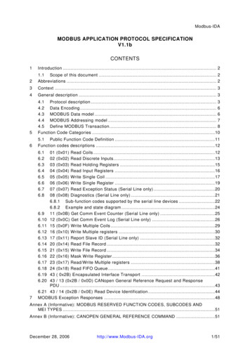
2:ModbusWhen it comes to planning data communication for open, multi-vendor industrial control systems,Modbus is the first choice of end users and integrators alike. The Modbus/RTU protocol defineshow a “master” device polls one or more “slave” devices to read and write data in real time bymeans of RS232, RS422, or RS485 serial data communication. Although not the most powerfulprotocol available, its rare simplicity allows not only rapid implementation but also enoughflexibility to apply in virtually all industrial situations. Modbus/TCP, an extension of Modbus/RTU,defines how Modbus/RTU and Modbus/ASCII messages are encoded within and transported overTCP/IP-based networks. Modbus/TCP is just as simple to implement and flexible to apply as theoriginal Modbus/RTU. You can find the specification for both online at www.telemecanique.com.The IAP device server allows users to integrate new and existing Modbus/RTU andModbus/ASCII serial devices with newer TCP/IP network-based devices. The next chapterdescribes a system that integrates four Modbus/RTU devices with four Modbus/TCP devices.Extended Modbus System ExampleFigure 2-1. Extended Modbus System ExampleFigure 2-1. Extended Modbus System Example shows four specific styles of Modbus operations.Modbus/RTU devices are traditionally split into two groups. (CoBox Modbus refers to an IAPdevice server.)Modbus slave devices generally are the workhorse devices. They perform their tasks 24 hours aday, 365 days a year, for example, tasks such as flow metering, temperature control, batchloading, or even running entire automated assembly lines. The slave devices are not called“slaves” because they work all the time; they are called slaves because as far as the datacommunications is concerned, they function as passive servers. Modbus slave devices passivelysit and wait for a remote Modbus master device to ask them to report existing data values (Read)or accept new data values (Write).Modbus master devices generally are higher-level computers, devices in which data andsoftware are very important. The most common examples of Modbus master devices are the“Human-Machine-Interface” (HMI) computers, which allow human operators to monitor, adjust,and maintain the operations of the field devices. Modbus master devices are clients that activelyModbus Protocol User Guide7
2: Modbusgo out and “read” from and/or “write” to remote Modbus slave devices to monitor or adjust slavebehavior.Modbus/TCP Master Talking to Modbus/TCP SlaveDevices A, B, E, and F are all new Modbus/TCP devices, which are improved over Modbus/RTU(see more about Modbus/RTU limitations below). All four devices can function concurrently asboth Modbus master and Modbus slave. Both computers A and B can treat controller E as aslave, polling data in real-time. Yet controller E can also act as a master and poll data fromcontroller F, which can in turn also act as a master to write alarm data directly up to computers Aand B to alert the operators to the alarm condition. Traditional Modbus/RTU requires slavedevices even with life threatening alarm conditions to sit patiently and wait for a remote master topoll the specific data that caused the alarm condition.It is revolutionary for such a simple and flexible protocol as Modbus to offer such functionality.Therefore, Modbus/TCP offers exciting new design options for industrial users, which theLantronix IAP device servers extend to traditional Modbus/RTU serial devices.Modbus/TCP Master Talking to Modbus/RTU Serial SlaveDevices D, G, and H are traditional Modbus/RTU slave devices. Device D uses a point-to-pointelectrical interface like RS232. This allows only a single Modbus/RTU master to talk to device D.However, the IAP device server makes device D appear on the Modbus/TCP network as a fullModbus/TCP slave device. All Modbus/TCP enabled devices, A, B, E, and F, can actively shareaccess to slave device D. A limitation in traditional Modbus/RTU implementation expects devicesto be dedicated as either master or slave devices, so device D can only act as a Modbus slave.Devices G and H are different from device D. They share a single RS485 “multi-drop” line thatstrictly limits them to act as slaves to a single Modbus/RTU master. However, a little of the newModbus/TCP and IAP device server magic still applies all Modbus/TCP enabled devices A, B,E, and F can actively share access to both slave devices G and H. IAP device server managesand coordinates the shared access. In fact, the IAP device server allows up to eight concurrentModbus masters to share access to the slaves.Modbus/RTU Serial Master Talking to Modbus/TCP SlaveDevice C is a traditional Modbus/RTU master device. Yet the IAP device server makes device Cappear to the TCP/IP network as a Modbus/TCP master plus all of the Modbus/TCP slaves onthe TCP/IP network (A, B, D, E, F, G, and H) appear as traditional Modbus/RTU slave devices.The only limitation is the traditional Modbus/RTU assumption that device C is dedicated as amaster only. Therefore Modbus/TCP master devices A, B, E, and F cannot treat device C as aModbus/TCP slave.Modbus/RTU Serial Master Talking to Modbus/RTU Serial SlaveFinally, master device C can poll traditional Modbus/RTU slave devices D, G, and H as if theywere directly multi-dropped on an attached RS485 line. The IAP device server transparentlybridges traditional Modbus/RTU devices across any TCP/IP network. This means users can startimplementing for Modbus/TCP long before all of their required products exist with Modbus/TCPand network interfaces.Modbus Protocol User Guide8
3:Configuring ModbusNetwork ProtocolsThe IAP device server uses TCP/IP protocols for network communication. The supportedstandards are ARP, UDP, TCP, ICMP, Telnet, TFTP, DHCP, and SNMP. For transparentconnections, TCP/IP (binary stream) or Telnet protocols are used. Firmware upgrades can bemade with the TFTP protocol.The IP protocol defines addressing, routing, and data block handling over the network. The TCP(transmission control protocol) assures that no data is lost or duplicated, and that everything sentinto the connection on one side arrives at the target exactly as it was sent.For typical datagram applications in which devices interact with others without maintaining apoint-to-point connection, UDP datagram is used.Packing AlgorithmTraditional Modbus/RTU requires a “character timeout” to signal the end of a Modbus/RTUpacket. This stretches out the overall response cycle. Fortunately, the IAP device server uses anintelligent length-predictive algorithm to detect the end of standard Modbus messages. Thisallows better performance and the IAP device server falls back to using a user definable“character time-out” to manage non-standard or user-defined Modbus functions.IP AddressEvery device connected to the TCP/IP network including the IAP device server must have aunique IP address. When multiple Modbus devices share a single IP, then Modbus/TCP includesan additional address called the Unit ID. See the product user guide for your specific IAP deviceserver for a complete description of IP Addressing.When the IAP device server is receiving Modbus/TCP messages from remote masters, the UnitID is converted to use in the Modbus/RTU message as the slave address.When the IAP device server is receiving Modbus/RTU messages from local serial masters, auser-defined lookup table is used to match the 8-bit Modbus slave address to a remote IPaddress. The Modbus slave address received is used as the Unit ID.Configuration MethodsThe IAP device server can be configured using remote or local methods. Either use an ASCIIterminal or a terminal emulation program to locally access the serial port or use a Telnetconnection to port 9999 to configure the unit over the network. See the product user guide foryour IAP device server.The IAP device server configuration is stored in nonvolatile memory and is retained withoutpower. The configuration can be changed any time. The IAP device server performs a reset afterthe configuration has been changed and stored.Modbus Protocol User Guide9
3: Configuring ModbusIAP Device Server IP AddressesThe IAP device server is shipped with a default IP address of 0.0.0.0, which automaticallyenables DHCP within the IAP device server.With a DHCP-enabled IAP device server, if there is a DHCP server to respond to IAP deviceserver’s request when it is booting up, the IAP device server will then get an IP address, agateway address, and a subnet mask from the DHCP server. These addresses will not be shownin the IAP device server’s Setup (configuration) screens (you will still see 0.0.0.0); however if youenter the Monitor Mode and from 0 prompt, type NC (upper case), the IP configuration of theIAP device server will display. . See 4: for more information.Using the Setup Mode Screen1. From the Lantronix DeviceInstaller configuration utility, click the Telnetbutton toopen a Telnet connection to the IAP device server. The IAP device server’s Ethernethardware address (or HW MAC) displays.2. By default for most devices, the password is the last 8 characters of the Device ID (fordevices manufactured after January 1, 2020) or is left blank (for all older devices). Please seeyour device user guide for more information.3. Within 5 seconds, press Enter to display the Setup (configuration) Mode screen. Here youcan change the parameters that define how the IAP device server does its job.Note: When you set up a new unit, and especially if you just reflashed the unit with anew firmware type, we recommend that you reset all of the parameters to the factorydefaults.4. To reset the parameters to the factory defaults, type D on the command line and press Enter.The default parameters display.5. Select an option on the menu (1-7) by typing the number of the option.6. To enter a value for a parameter, type the value and press Enter, or to confirm a defaultvalue, press Enter.7. Review your entries.8. You have the following options:To save the configuration and exit, type S on the command line and press Enter. This saves theparameters to EEPROM.Caution: DO NOT POWER CYCLE the unit too fast after doing this. Allow the unit toreboot naturally one time first.To quit without saving, type Q on the command line and press Enter. The unit reboots.To restore the default values, type D on the command line and press Enter.Modbus Protocol User Guide10
3: Configuring ModbusFigure 3-1. Setup (Configuration) Mode ScreenBasic Commands (D/S/Q)Figure 3-1. Setup (Configuration) Mode Screen shows the main IAP device server configurationmenu. The IAP device server offers three basic options.Default Settings (D)Entering D resets all parameters to the factory default as shown above. Only the IP address doesnot change. Although not required, selecting this option immediately after reloading the firmwareand saving it ensures that the unit resets.Save (S)Entering S saves the currently displayed parameter settings into non-volatile memory and exitsconfiguration mode. This option triggers a reset.Quit Without Saving (Q)Entering Q cancels any parameter changes you have made and exits configuration mode. Thisoption triggers a reset.Modbus Protocol User Guide11
3: Configuring ModbusNetwork/IP SettingsSelect 1 to configure the device server’s network parameters.The following values can be set or changed. To understand and select the appropriate values,consult one of the many TCP/IP books available today and your network administrator.IP AddressThe IP address must be set to a unique value on your network. If you are not familiar with IPaddressing on your network, please consult your network administrator. Please refer to the IAPuser guide for your device server for more details about IP addresses.If the IAP device server is set to an address already in use, it displays an error code with theLEDs and will not operate properly. If you plan to use DHCP, set the IP to 0.0.0.0 to activateDHCP.Set Gateway IP Address (Y/N)Most users could select N for this case. You only need to choose Y if the IAP device server mustcommunicate to remote TCP/IP networks through a router or gateway. If you select Y, you mustalso enter the IP address of the default gateway within your local network.Set Netmask (N for default)Most users could select N, which causes the IAP device server to automatically use the standardnetmask appropriate for the IP address entered. Users who want a non-standard netmask needto enter the new subnet mask in the traditional form, for example, 255.255.248.000.Telnet Configuration PasswordPlease protect your device from unauthorized access and follow the instructions below:Always select Y to enable Telnet/Web Manager passwordEnable the enhanced password setting and create a strong 16-character password. For details,see Security Settings on page 18.Note: We do not recommend that you only use the 4-character basic password as it doesnot offer sufficient security. Using no password is very dangerous.Serial and Mode SettingsSelect 2 to change the basic serial parameters. The following values can be set or changed.Attached Device (1 Slave, 2 Master)As mentioned in the introduction, Modbus/RTU devices are defined as either slave or masterdevices. Type 1 if the attached device is a slave (such as controller or PLC) or 2 if the attacheddevice is a master (such as a computer running graphical human-machine-interface (HMI)software).Modbus Protocol User Guide12
3: Configuring ModbusSerial Protocol (1 Modbus/RTU, 2 Modbus/ASCII)Serial Modbus comes in two forms. Modbus/RTU uses 8-bit data bytes to send binaryinformation. However, some devices cannot handle 8-bit data bytes, so Modbus/ASCII is used.Modbus/ASCII is a slower protocol, where each 8-bit data byte is converted to 2 ASCIIcharacters. Since the IAP device server converts both to and from Modbus/TCP fully, you can mixany combination of RTU and ASCII devices on a Modbus/TCP network. So a Modbus/RTUmaster attached to one IAP device server can remotely access a Modbus/ASCII slave attached toanother IAP device server.Interface Type (1 RS232 2 RS422/RS485 4-wire 3 RS485 2-wire)This allows the IAP device server to deal with the software-related details of using RS232,RS422, and RS485.With the XPress DR-IAP, you still must set the external red RS232/RS485 switch appropriately.With the UDS-10-IAP or CoBox-FL-IAP, you must still select the correct pins for RS232 or theshared RS422/485 pins.Enter Serial Parameters (B,D,P,S)Enter the baud rate (300/ 600/ 1200/ 2400/ 4800/ 9600/ 19,200/ 38,400/ 57,600/ or 115,200),data bits (7/8), parity (N/O/E), and stop bits (1/2) in the classic “DOS Mode Command” style.Examples are 9600, 8, E, 1 or 1200, 7, O, 2. These settings must match the settings on theattached Modbus device.The UDS-10-IAP supports only 1 stop bit. If you try to set an unsupported combination of settings,a warning displays.Note: Regardless of these settings, IAP device server configuration is always done onCH1 with RS232 and a setting of 9600,8,N, 1.Modem Control SettingsWhen using RS232, the IAP device server has a number of user-definable “Modem Control”parameters to manage RTS/CTS handshaking for half-duplex radio modems.RTS/CTS Mode (1 Fixed 2 Variable)Answer 1 and the IAP device server output is fixed to high. Answer 2 to enable modemhandshaking. The RTS/CTS output is active when the device server is transmitting on the serialport. This setting is very different from the hardware or RTS/CTS flow-control used with printers.This mode cannot work with a direct RS232 cable, as each end only asserts its RTS controlsignal to power up intermediate transmitters.The XPress DR-IAP has a DTE-style RS232 port, so RTS is an output and CTS is an input. TheUDS-10-IAP and CoBox-FL-IAP have a DCE-style RS232 port, so RTS is an input and CTS is anoutput.Delay after Output of RTS (0-1275 ms, 5ms increments)Only asked if RTS/CTS mode is variable. After the IAP device server asserts the RTS/CTSsignal, it delays from 0 to 1275 ms before continuing. Normally this is set to 0. Only set a valuehere if your device, modem, or cable is non-standard.Modbus Protocol User Guide13
3: Configuring ModbusWait for CTS to Go Active (N/Y)Only asked if RTS/CTS mode is variable. Answering N causes the IAP device server to ignore theRTS/CTS response from the modem. Answering Y causes the IAP device server to wait for theRTS/CTS response from the modem. Do not answer Y unless you know that the cable is wiredproperly to support this signal.Delay after CTS Going Active (0-1275 msec, 5 msec increments)Only asked if RTS/CTS mode is variable and set to wait for CTS to go active. After the IAP deviceserver sees the modem assert an RTS/CTS response input, it delays from 0 to 1275 milliseconds(msec) before transmitting. If the IAP device server waits without seeing a valid response fromthe modem, it will return the Modbus exception response 0x0B (hex) to the Modbus/TCPrequesting master.Delay Dropping RTS after Transmitting (0-1275 msec, 5 msec increments)Only asked if RTS/CTS mode is variable. After the IAP device server completes transmission, itdelays from 0 to 1275 msec before dropping the RTS/CTS output.Advanced Modbus Protocol SettingsChanging these parameters takes a bit of thought and planning.Slave Address (0 for auto, or 1 255 fixed otherwise)Modbus/TCP includes a Unit ID field, which is used to address multiple Modbus slaves at a singleIP address. Unfortunately, some first generation software drivers assumed a single slave at eachIP and always set the Unit ID field to 0. This causes the IAP device server problems because itrequires the Unit ID for the Modbus/RTU “Slave Address.” To support these older applications,the IAP device server allows you to force a fixed address for Modbus/RTU and Modbus/ASCII,but note that this restricts you to a single serial slave device per IAP device server.Setting this value to 0 causes the IAP device server to use the Modbus/TCP Unit ID as received.Setting it to any other address causes the IAP device server to always use the set value as afixed address.Allow Modbus Broadcasts (1 Yes 2 No)This relates to the previous issue. The default is 2/No, in which case the IAP device serveralways assumes a Modbus/TCP “Unit ID” of 0 really means Modbus slave address 1. AnsweringNo here is like setting a fixed address of 1 (parameter above), except the fixed address is onlyused if the Modbus/TCP “Unit ID” is 0.Note: In the current software version for IAP device server, a true Modbus broadcast isonly supported when a serial slave device is attached. A Modbus broadcast from a serialmaster device is discarded regardless of this parameter setting.Use MB/TCP 0x0B/0x0A Exception Responses (1 No 2 Yes)Traditional serial Modbus uses silence to signal some errors. While this works well with directserial lines, it causes serious problems on a TCP/IP wide-area-network where delays are not sopredictable. . See 4: for more information.Modbus Protocol User Guide14
3: Configuring ModbusSetting this parameter to 1/No causes the IAP device server to behave like a traditional Modbusserial slave – it answers timeouts, unconfigured slave addresses, and CRC errors with silence.Setting this to 2/Yes causes the IAP device server to return 1 of 2 new exception codes defined inModbus/TCP.Consider exception hex 0A (PATH UNAVAILABLE) a “hard” error where a retry is not likely tosucceed. It is returned:If slave-attached – currently never. However, future firmware may allow the user to define therange of valid slave addresses.If master-attached – if a Modbus request has a slave address that is not configured in the Unit IDto IP mapping table.If master-attached – if the TCP socket failed to open. This is really a soft-hard error, as thereason the TCP socket failed to open may be transient or a hard configuration error.Consider exception hex 0B (TARGET DEVICE FAILED TO RESPOND) a “soft” error where aretry may succeed. It is returned:If slave-attached – if the slave didn’t answer or the answer contained a CRC errorIf master-attached – if a TCP socket is open, but no response was received in the definedmessage timeout.If master-attached – if a TCP socket is open, but the remote Modbus/TCP slave/server returnedexception 0x0B.Disable Modbus/TCP pipeline (1 No 2 Yes)While the Modbus/TCP standard specification requires Modbus/TCP masters/clients to only issueone poll at a time, the full-duplex flow-controlled nature of TCP/IP allows them to issue more thanone at a time, and the TCP socket will buffer them. The IAP device server will fetch them one at atime and answer each in turn. See 4: for more information.Setting this to 1/No causes the IAP device server to allow this queuing or pipeline behavior. Thisis the safest default setting – only change this to disable if you are having problems.Setting this to 2/Yes causes the IAP device server to always fetch the newest request from theTCP buffer – all older requests are discarded. This allows a Modbus/TCP master/client to retryold requests without risking building up a stale queue of waiting requests.Character Timeout (10-7050 msec)This sets the timeout between characters received. Official Modbus/RTU defines a 3.5 charactertime-out, but complex devices have various interrupts that can cause 5 to 10 character “pauses”during transmission. A safe value for general use with Modbus is 50 msec.Note: Setting this value lower than 50 msec will not improve performance and may evenmake performance worse. The IAP device server uses an intelligent length-predictingalgorithm to detect end-of-message in Modbus/RTU. This “character timeout” is onlyused with user-defined or non-standard Modbus functions.Message Timeout (200-65000 msec)This sets the timeout for a response from a connected slave both serially and by TCP/IP.Modbus Protocol User Guide15
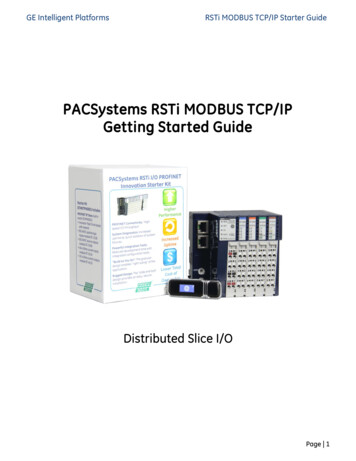
3: Configuring ModbusSerial TX delay after RX (0-1275 msec) (0)This feature inserts a delay between the Modbus/TCP master requests. The first request is sentout of the serial port of the IAP device server to the Modbus slave. When the slave’s responseenters the serial port of the IAP device server, it triggers this timer. After the specified delay isreached, the next master request is allowed to pass through the serial port of the IAP deviceserver, and the timer is reset. This feature is particularly useful when using RS485 2-wired serialprotocol. The delay gives ample time for the RS485 slave devices to turn their transmitters off andtheir receivers back on.Swap 4x/0x to get 3x//x (1y)This setting allows the MBF to convert “input” resistor data to “holding” resistor data. It alsoconverts coil and contact data. This feature is useful for Modicon I/O scanners.Unit ID to IP Address Lookup TableFigure 3-2. Unit ID to IP Address Lookup TableSince serial Modbus uses 8-bit slave addresses and a TCP/IP network requires 32-bit IPaddresses, the IAP device server uses this table to map an 8-bit address into an IP/Unit IDcombination. The 8-bit address is used to select the desired IP and as the Unit ID sent. The tableholds 8 entries, and any Modbus slave address not found in the table returns an exceptionresponse to the master (if enabled).The example below is of adding an entry. Select 5 to edit/view settings.Modbus Protocol User Guide16
3: Configuring ModbusFigure 3-3. Unit ID to Address Lookup Table ExampleClose Idle TCP sockets after (1-60 sec, 0 leav
IP Address Every device connected to the TCP/IP network including the IAP device server must have a unique IP address. When multiple Modbus devices share a single IP, then Modbus/TCP