Transcription
UDS200User GuidePart Number 900-303Revision D December 2007
Copyright & Trademark 2004, 2007 Lantronix. All rights reserved. No part of the contents of this book maybe transmitted or reproduced in any form or by any means without the writtenpermission of Lantronix. Printed in the United States of America.Ethernet is a trademark of XEROX Corporation. UNIX is a registered trademark ofThe Open Group. Windows 95, Windows 98, Windows 2000, and Windows NT aretrademarks of Microsoft Corp. Netscape is a trademark of Netscape CommunicationsCorporation.ContactsLantronix Corporate Headquarters15353 Barranca ParkwayIrvine, CA 92618, USAPhone: 949-453-3990Fax:949-453-3995Technical Supporthttp://www.lantronix.com/supportSales OfficesFor a current list of our domestic and international sales offices, go to the Lantronixweb site at www.lantronix.com/about/contact.Disclaimer & RevisionsOperation of this equipment in a residential area is likely to cause interference, inwhich case the user, at his or her own expense, will be required to take whatevermeasures may be required to correct the interference.Note: This product has been designed to comply with the limits for a Class Adigital device pursuant to Part 15 of FCC Rules. These limits are designed toprovide reasonable protection against such interference when operating in acommercial environment. This equipment generates, uses, and can radiateradio frequency energy, and if not installed and used in accordance with thisguide, may cause harmful interference to radio communications.Changes or modifications to this device not explicitly approved by Lantronix will voidthe user's authority to operate this device.The information in this guide may change without notice. The manufacturer assumesno responsibility for any errors that may appear in this guide.Date Rev. Comments4/03A Initial Document6/04B Reorganized, added application examples10/04C Updated12/07D Corrected warranty page and technical support information2
ContentsFigures6Tables61: Using This Guide7Purpose and Audience 7Chapter Summary 7Additional Documentation 82: Introduction9Applications 9Application Examples 9Protocol Support 10Additional Features 11Configuration Methods 11Product Information Label 113: Getting Started12Installing the UDS200 12Required Information 13Hardware Address 13IP Address 13Assigning the IP Address and Related Network Settings 14DeviceInstaller 14Serial Port Login 154: Configuring the UDS Using Web Manager16Accessing Web Manager 16Configuring the UDS 185: Configuring the UDS Using Telnet or the Serial Port20Using a Telnet Connection 20Using the Serial Port 22Server Configuration (Network Configuration) 22IP Address 22Set Gateway IP Address 23Netmask 23Change Telnet configuration password 233
DHCP Naming 23Channel 1 Configuration (Serial Port Settings) 24Baudrate 24I/F (Interface) Mode 24Flow 25Port Number 25Connect Mode 26Manual Connection 27Remote IP Address 30Remote Port 30Disconnect Mode 31Flush Mode 31Pack Control 32Disconnect Time (Inactivity Timeout) 33Send Characters 33Telnet Terminal Type 33Channel (Port) Password 33Expert Settings 33TCP Keepalive time in s 34ARP Cache timeout in s 34Security Settings 34Disable SNMP 34SNMP Community Name 34Disable Telnet Setup 35Disable TFTP Firmware Upgrade 35Disable Port 77FE (Hex) 35Disable Web Setup 35Disable ECHO Ports 35Enable Enhanced Password 35Factory Default Settings 36Channel 1 and Channel 2 Configuration Defaults 36Expert Settings Defaults 36Security Settings Defaults 36Exiting Configuration Mode 366: Updating Firmware37Obtaining Firmware 37Reloading Firmware 37Using DeviceInstaller 37Using TFTP 384
Using Another Unit 39Using the Serial Port 397: Using Monitor Mode41Entering Monitor Mode Using the Serial Port 41Entering Monitor Mode Using the Network 41Using Monitor Mode Commands 428: Troubleshooting and Technical Support43LEDs 43Problems and Error Messages 44Technical Support 479: Technical Specifications4910: Connections and Pinouts50UDS200 Serial Ports 50Serial Connector Pinouts 50Network Port 51Ethernet Connector Pinouts 51Null-Modem Cable 51A: Alternative Ways to Assign an IP Address53DHCP 53AutoIP 53BOOTP 54ARP and Telnet 54B: Binary to Hexadecimal Conversions55Converting Binary to Hexadecimal 55Conversion Table 55Scientific Calculator 56Connect Mode Options 57Disconnect Mode Options 60Flush Mode (Buffer Flushing) Options 62Interface Mode Options 67Pack Control Options 67Declaration of Conformity69Warranty70Index715
FiguresFigure 2-1. Application Examples . 10Figure 2-2. Sample Hardware Address. 11Figure 3-1. UDS200 Connected to Serial Device and Network . 12Figure 4-1. Web Browser Login . 16Figure 4-2. UDS Configuration Guidelines Page . 17Figure 4-3. Lantronix Web Manager . 18Figure 4-4. Server Properties Configuration on the Web Browser . 19Figure 5-1. Network Login Using Telnet . 20Figure 5-2. Setup Mode Window . 21Figure 5-3. Network Configuration . 22Figure 5-4. Server Configuration Option . 24Figure 5-5. Channel 1 Configuration. 24Figure 5-6. Hostlist Option . 28Figure 5-7. Expert Settings Options. 33Figure 5-8. Security Settings. 34Figure 6-1. TFTP Dialog Box . 38Figure 6-2. Sending Firmware to another Unit. 39Figure 6-3. Firmware Upgrade Screen Display. 39Figure 7-1. Entering Monitor Mode Using the Network. 41Figure 10-1. Serial Interface. 50Figure 10-2. DB9 Male RS232 Serial DTE Connector. 50Figure 10-3. Network Interface . 51Figure 10-4. RJ45 Ethernet Connector . 51Figure 10-5. Null-Modem Cable (Lantronix Part No. 500-164) . 52TablesTable 5-1. Netmask ExamplesTable 5-2. Interface Mode OptionsTable 5-3. Common Interface Mode SettingsTable 5-4. Flow Control OptionsTable 5-5. Connect Mode OptionsTable 5-6. Manual Connection Address ExampleTable 5-7. Modem Mode CommandsTable 5-8. Disconnect Mode OptionsTable 5-9. Flush Mode OptionsTable 5-10. Pack Control OptionsTable 7-1. Monitor Mode CommandsTable 7-2. Command Response CodesTable 8-1. UDS200 LEDsTable 8-2. Problems and Error Messages23252525262730313132424244446
1: Using This GuidePurpose and AudienceThis guide provides the information needed to configure, use, and update theUDS200 device server. It is for system administrators and those responsible forinstalling and maintaining the UDS200.Chapter SummaryThe remaining chapters in this guide include:2: IntroductionDescribes the main features of the UDS200 and theprotocols it supports.3: Getting StartedProvides information for installing your unit and getting it upand running.4: Configuring the UDSUsing Web ManagerProvides instructions for accessing Web Manager and usingit to configure settings for the UDS.5: Configuring the UDSUsing Telnet or the SerialPortProvides instructions for accessing Setup Mode (commandline interface) using a Telnet connection through thenetwork or a terminal or terminal emulation program throughthe serial port. Details the settings that you must configure.6: Updating FirmwareProvides instructions for obtaining the latest firmware andupdating the UDS200.7: Using Monitor ModeProvides instructions for accessing and using the commandline interface to monitor the network and diagnoseproblems.8: Troubleshooting andTechnical SupportDescribes common problems and error messages and howto contact Lantronix Technical Support.9: Technical SpecificationsLists technical specifications for the UDS200.10: Connections and Pinouts Provides descriptions and illustrations of connectionhardware.A: Alternative Ways toAssign an IP AddressProvides detailed information about using DHCP, AutoIP,BOOTP ARP, and Telnet to assign an IP address.B: Binary to HexadecimalProvides instructions on converting binary values tohexadecimals and tables listing all configuration options inhexadecimal notation.7
UDS200 User GuideUsing This GuideAdditional DocumentationThe following guide is available on the product CD or the Lantronix Web site:www.lantronix.com.DeviceInstaller UserGuideProvides instructions for using the Windows-based utility toconfigure the UDS and other Lantronix device servers. (CD andweb site)8
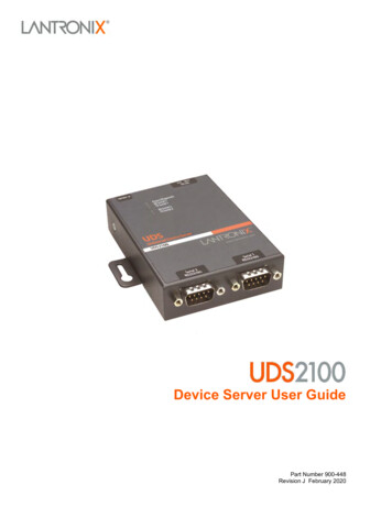
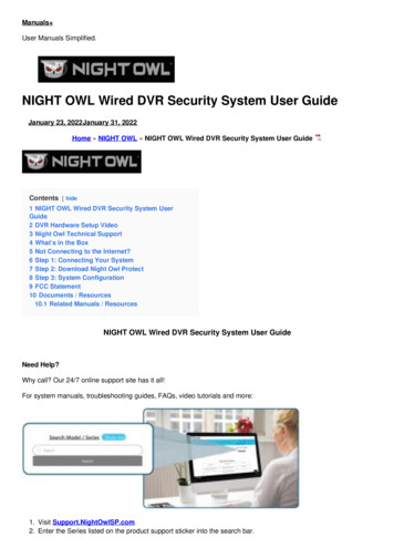
2: IntroductionApplicationsThe UDS family of Device Servers allows serial devices, such as those listed below,to connect and communicate over Ethernet networks using the IP protocol family(TCP for connection-oriented stream applications and UDP for datagramapplications). Security alarms Access control devices Fire control panels Time/attendance clocks and terminals ATM machines Data collection devices RFID readers Universal Power Supply (UPS) management units Telecommunications equipment Data display devices Virtually any asynchronous RS-232, RS422, or RS485 device.Application ExamplesUsing a method called serial tunneling, the UDS200 encapsulates serial data intopackets and transports them over Ethernet. Using two UDS200 units, connected by anetwork, virtual serial connections can extend across a facility or around the world.The Com Port Redirector software included on the product CD simplifies theintegration process by extending the functionality of COM-port-based Windows applications. Virtual COM ports, mapped to remote device servers on the network,can replace direct serial connections.9
IntroductionUDS200 User GuideFigure 2-1. Application ExamplesNote: For step-by-step instructions on configuring the UDS for serialtunneling or for use with the Com Port Redirector, access the UDSConfiguration Tutorials using Web Manager. (See Accessing Web Manager.)Protocol SupportThe UDS200 uses the Internet Protocol (IP) for network communications and theTransmission Control Protocol (TCP) to assure that no data is lost or duplicated, andeverything sent to the connection arrives correctly at the target.Other protocols supported are: ARP, UDP, TCP, ICMP, Telnet, TFTP, AutoIP, DHCP, HTTP, and SNMP fornetwork communications. TCP, UDP, and Telnet for connections to the serial port. TFTP for firmware updates. IP for addressing, routing, and data-block handling over the network. User Datagram Protocol (UDP) for typical datagram applications in whichdevices interact with other devices without maintaining a point-to-pointconnection.10
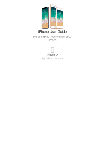
IntroductionUDS200 User GuideAdditional FeaturesModem Emulation: In modem emulation mode, the UDS200 can replace dial-upmodems. The unit accepts modem AT commands on the serial port, and thenestablishes a network connection to the end device, leveraging network connectionsand bandwidth to eliminate dedicated modems and phone lines.Built-in Web Server: The UDS200 includes a built-in web server for configuring theunit and displaying operating and troubleshooting information on the attached links toonline support.Configuration MethodsAfter installation, the UDS200 requires configuration. For the unit to operate correctlyon a network, it must have a unique IP address on the network. There are three basicmethods for logging into the UDS200 and assigning IP addresses and otherconfigurable settings:DeviceInstaller: Configure the IP address and other network settings on theUDS200 using a Graphical User Interface (GUI) on a PC attached to a network. SeeDeviceInstaller on page 14.)Web Manager: Through a web interface, configure the UDS200 settings using theLantronix Web Manager. (See 4: Configuring the UDS Using Web Manager.)Serial and Telnet Ports: There are two approaches to accessing Setup Mode:making a Telnet connection to the network port (9999) or connecting a terminal (or aPC running a terminal emulation program) to the unit’s serial port. (See 5:Configuring the UDS Using Telnet or the Serial Port.)Product Information LabelThe product information label on the underside of the unit contains the followinginformation about your specific unit: Bar code Serial number Product ID (name) Product description Hardware address (also referred to as Ethernet or MAC address)The first three bytes of the hardware address are fixed and read 00-20-4A, identifyingthe unit as a Lantronix product. The fourth, fifth, and sixth bytes are unique numbersassigned to each unit.Figure 2-2. Sample Hardware Address00-20-4A-14-01-18 or 00:20:4A:14:01:1811
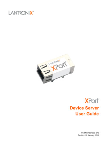
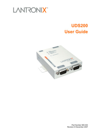
3: Getting StartedThis chapter describes how to get your UDS up and running in the shortest possibletime.Installing the UDS200The following diagram shows a properly installed unit:Figure 3-1. UDS200 Connected to Serial Device and NetworkTo install the unit, complete the following steps in order. Refer to the numbers in theprevious figure.1. Connect a serial device to your unit. See 10: Connections and Pinouts for moreinformation about what kinds of device attachments the unit supports.2. Connect an Ethernet cable to the 10/100 port.3. Supply power to your unit using the power supply that was included in thepackaging.Note: The required input voltage is 9-30 VDC or 9-24 VAC(2W maximum).4. Supply power to the serial device.Note: If you encounter a problem, please see LEDs on page 43 fordiagnostic information.12
Getting StartedUDS200 User GuideRequired InformationHardware AddressTake note of the unit’s hardware address (also known as the MAC or Ethernetaddress). It is on the product label, in the format: 00-20-4a-XX-XX-XX, where the XXsare unique numbers assigned to the product (see Product Information Label on page11).Hardware Address: 00-20-4a- - -IP AddressThe UDS must have a unique IP address on your netw
Introduction UDS200 User Guide 10 Figure 2-1. Application Examples Note: For step-by-step instructions on configuring the UDS for serial tunneling or for use with the Com Port Redirector,