Transcription
xPico 200 SeriesEmbedded Wi-Fi GatewayData SheetPart Number 900-818Revision H October 2019
Table of ContentsxPico 200 Series Embedded Wi-Fi Gateway Data Sheet1Table of Contents 2List of Figures 4List of Tables 51: Functional Description7Overview 7Applications 7Product Features 82: Hardware and Software Description9xPico 200 Block Diagram 11Software Features 113: Pin and Pad Definitions164: Interfaces22EthernetUARTUSB Host InterfaceSPI Slave InterfaceSPI Master InterfaceConfigurable General Purpose I/O Pins (GPIO)System PinsStrap Pins22222324242425265: IEEE 802.11 Wireless Lan Specifications276: Bluetooth Specifications317: Antenna Connection Options328: Electrical Characteristics33Recommended Operating ConditionsDC Characteristics – Digital I/O SignalsDynamic Power Management ModesOutput PowerInput PowerEVMRX SensitivityxPico 200 Series Embedded Wi-Fi Gateway Data Sheet333334363737382
Power, Reset, Wake, Shutdown and Default TimingSPI Slave TimingSPI Master TimingMemory9: Package Description and Mechanical Footprint3840414243Dimensions 43Material and Weight 4510:Product Information Label4611:Compliance47Labeling of the End ProductFederal Communication Commission Interference Statement (xPico 240/250/270)Industry Canada Statement (xPico 240/250/270):RoHS, REACH, and WEEE Compliance Statement12:Ordering Information4849505657Warranty 58Contact Information 58xPico 200 Series Embedded Wi-Fi Gateway Data Sheet3
List of FiguresFigure 2-1 xPico 240 Module Options 10Figure 2-2 xPico 250 and xPico 270 Module Options 10Figure 2-3 xPico 200 Block Diagram 11Figure 2-4 Wi-Fi Integration Mode 12Figure 2-5 Wireless Microcontroller Mode 12Figure 3-1 xPico 200 Edge Connector Pin & Signal Location 16Figure 3-2 xPico 200 PCB Interface Pin & Signal Location 18Figure 8-1 Reset Timing 38Figure 8-2 Reset to Defaults Timing 39Figure 8-3 Wake Timing 39Figure 8-4 SPI Slave Timing 40Figure 8-5 SPI Master Timing 41Figure 9-1 xPico 200 Embedded Wi-Fi Gateway (On-Module Antenna) 43Figure 9-2 xPico 200 Embedded Wi-Fi Gateway (Dual U.FL) 43Figure 9-3 Layout Footprint for xPico 200 Enterprise Wi-Fi IoT Module 44Figure 9-4 xPico 200 Edge Connector Footprint Dimensions 45Figure 10-1 xPico 200 Module Label 46Figure 11-1 EU Declaration of Conformity (xPico 240/250) 53Figure 11-2 EU Declaration of Conformity (xPico 270) 54xPico 200 Series Embedded Wi-Fi Gateway Data Sheet4
List of TablesTable 3-1: xPico 200 Edge Connector Signal DescriptionsTable 3-2: xPico 200 PCB Interface Signal DescriptionsTable 4-1: xPico 200 UART Signal DefinitionsTable 4-2: xPico 200 USB Host Interface Signal DefinitionsTable 4-3: xPico 200 SPI Slave Interface Signal DefinitionsTable 4-4: xPico 200 SPI Master Interface Signal DefinitionsTable 4-5: xPico 200 Module GPIO Signal DefinitionsTable 4-6: xPico 200 Strap PinsTable 5-1: xPico 200 Module Radio SpecificationTable 5-2: 20 MHz ChannelsTable 5-3: 40 MHz ChannelsTable 5-4: 80 MHz Channels (xPico 270 only)Table 5-5: Wireless Throughput, 802.11ac, TCPTable 5-6: Wireless Throughput, 802.11ac, UDPTable 5-7: Wireless Throughput, 802.11n, TCPTable 5-8: Wireless Throughput, 802.11n, UDPTable 6-1: xPico 200 BT Radio Specification (xPico 250/270 only)Table 7-1: External Antenna OptionsTable 7-2: On-Module Antenna OptionTable 8-1: Recommended Operating Conditions for xPico 200 ModuleTable 8-2: DC Characteristics & Digital I/0 SignalsTable 8-3: xPico 200 Power Consumption 2.4 Ghz (@3.3V, 25 oC), Bluetooth DisabledTable 8-4: xPico 200 Power Consumption 5 Ghz (@3.3V, 25oC), Bluetooth DisabledTable 8-5: xPico 250/270 Power Consumption with Bluetooth Enabled (@3.3V, 25 oC)Table 8-6: xPico 200 Module RF Output Power (Wi-Fi Conducted)Table 8-7: xPico 200 Module RF Output Power (BT Conducted)Table 8-8: xPico 200 Module RF Input Power Wi-Fi 2.4GhzTable 8-9: xPico 200 Module RF Input Power Wi-Fi 5GhzTable 8-10: xPico 200 Module RF Input Power BTTable 8-11: xPico 200 Module Wi-Fi EVMTable 8-12: xPico 200 Module Rx Sensitivity @ 3.3V input power, 25oCTable 8-13: Shutdown Pin TimingTable 8-14: SPI Slave TimingTable 8-15: SPI Master TimingTable 9-1: Material and WeightTable 10-1: Datamatrix ECC200 Barcode Standard DescriptionsTable 11-1: Country Certifications (xPico 240/250/270)Table 11-2: Country Transmitter IDs (xPico 240)Table 11-3: Country Transmitter IDs (xPico 250)Table 11-4: Country Transmitter IDs (xPico 270)Table 11-5: Europe – EU Declaration of Conformity (xPico 240/250/270)Table 12-1: xPico 240 Order InformationxPico 200 Series Embedded Wi-Fi Gateway Data 5363636373737373839404145464748484855575
Table 12-2: xPico 250 Order Information 57Table 12-3: xPico 270 Order Information 57xPico 200 Series Embedded Wi-Fi Gateway Data Sheet6
1: Functional DescriptionOverviewThe Lantronix xPico 200 series of embedded IoT gateways is one of the smallest and mosthighly integrated industrial Wi-Fi , Ethernet and Bluetooth combo solutions, allowing you todeliver and manage secure connected products without added complexity and risk.The xPico 200 series delivers always-on dual-band enterprise Wi-Fi, dual-mode Bluetooth(Bluetooth Classic v2.1 EDR and Bluetooth Low Energy v4.2) as well as Ethernet connectivityfor business-critical assets.It is a standalone module that does not require an external host processor for the wireless andnetwork stack. With customer proven TruPort technology that includes production-readyessential IoT connectivity firmware, cloud-based management and an integrated devicesecurity framework, xPico 200 series delivers a complete network and IoT connectivity offloadsolution for any microcontroller.Device manufacturers can use xPico 200 series as the wireless microcontroller within theirdevice and focus on the application firmware components while leveraging the integratedsecure connectivity network and cloud service enablement capabilities within the module.The high performance xPico 200 series is available in different versions(see Product Features).With the xPico 200 family, design engineers and system architects can reduce productdevelopment time and deploy their secure connected devices with confidence that theirproducts will connect and work as expected.ApplicationsFor applications that need Ethernet and wireless connectivity options, xPico 200 delivers acompact combo solution without needing to integrate two different network stacks fromdifferent modules or controllers.Integrated Bluetooth capability on xPico 250/270 enables gateway functions that need toaggregate Bluetooth sensor devices or communicate with Bluetooth peripherals and mobiledevices.Key applications include: Medical devices Industrial machines Retail/POS Weighing scales Asset and warehouse management Environmental monitoring Transportation and TelematicsThe xPico 200 series is designed for applications in a variety of industries where reliability,extended operating temperature range, and robust wireless connectivity are business-critical.The xPico 200 series is also particularly well-suited for products with long lifecycles in highlyxPico 200 Series Embedded Wi-Fi Gateway Data Sheet7
regulated industries where the constant change in Wi-Fi technologies and certification wouldtypically make it difficult or cost prohibitive to incorporate a wireless solution.Product Features Dual-band (802.11 a/b/g/n) for high performance industrial Wi-Fi xPico 270 adds 802.11ac 2.4 GHz and 5 GHz bands supported IEEE 802.3 10/100 Mbps Ethernet (RMII) Compliant with Bluetooth Core Specification version 4.2 including BLE - xPico 250/270 Support for Bluetooth Generic Access Profile (GAP), Generic Attribute Profile (GATT),Device ID Profile - xPico 250/270 On-module antenna or Dual U.FL UART (x1), SPI Master (x1), SPI Slave (x1), USB Host/Device and GPIO Ethernet MAC (RMII), USB, UART – host interfaces Simultaneous AP and client (STA), AP only, client (STA) only modes Support for up to 5 simultaneous client connections to Soft AP interface TruPort Serial and TruPort Socket providing industry’s most compatible device dataaccess technology InfiniShield Security – adding integrated root of trust security and data-at-rest and datain-motion encryption, authentication and identification Direct mobile to device service interface via SoftAP technology (xPico 240/250/270) orBluetooth (xPico 250/270) WPA/WPA2 – Personal and Enterprise Wi-Fi Security SSL/TLS 1.2 with X.509 Certificate Management Dual Network Support Embedded Ethernet to Wi-Fi STA or Ethernet to Wi-Fi Soft AP bridge Integrated Cloud Based Device Management via MACH10 platform Web Service API, XML Configuration, Serial Command API Modular RF Certification (FCC, IC, ETSI, Japan, AU/NZS, China) Compact SMT (LGA) Footprint (17mm x 25 mm) or Edge Connector Card Footprint (22mm x 35.5 mm) Operating temperature range: -40⁰C to 85⁰C 5-year limited warrantyxPico 200 Series Embedded Wi-Fi Gateway Data Sheet8
2: Hardware and Software DescriptionThe xPico 200 series is a highly integrated module that includes a Cortex R4 controller, 802.11a/b/g/n MAC/BB, 10/100 Mbps Ethernet MAC, Bluetooth 4.2 (on xPico 250/270), RAM, flash, andtwo U.FL antenna connectors or a single on-module antenna (on the xPico 240 only). xPico 270adds 802.11ac.The module also includes the following data communication interfaces: One 10/100Mbps Ethernet MAC with RMII interface for connection to an external PHY One USB 2.0 high speed Host/Device port One 300 to 4Mbps UART with hardware flow control One SPI Slave port operating up to 50 MHz clock rate (5 Mbps application throughput) Up to 10 GPIO linesThe xPico 200 series operates on 3.3V power with 3.3V logic, and has a built-in voltagesupervisory circuit.xPico 200 series offers two main variants depending on the connectivity interfaces available: xPico 240 - Provides dual-band 802.11abgn Wi-Fi and Ethernet combo xPico 250 - Provides dual-band 802.11abgn Wi-Fi, Ethernet and dual-mode Bluetooth(Bluetooth Classic and Bluetooth Low Energy) xPico 270 - Provides dual-band 802.11ac/abgn Wi-Fi, Ethernet and dual-mode Bluetooth(Bluetooth Classic and Bluetooth Low Energy)The xPico 200 comes in two form factors: Small form factor SMT module Edge connector module with standard connectorxPico 240 has two antenna options: Two U.FL for connection to external antennas for single stream diversity. SeeChapter 7: Antenna Connection Options for recommended antennas. Single on-module antennaxPico 250 and xPico 270 have one antenna option: Two U.FL for connection to external antennas. One antenna dedicated for Wi-Fi andone dedicated for BT. See Chapter 7: Antenna Connection Options for recommendedantennas.xPico 200 Series Embedded Wi-Fi Gateway Data Sheet9
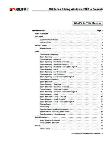
Figure 2-1 xPico 240 Module OptionsXPC2401 – LGA, Dual U.FLXPC2402 – LGA, On-Module AntennaXP2403 – Edge Connector, Dual U.FLXPC2404 – Edge Connector,On-Module AntennaFigure 2-2 xPico 250 and xPico 270 Module OptionsXPC2501, XPC2701 – LGA, Dual U.FLXPC2503, XPC2703 – Edge Connector, Dual U.FLxPico 200 Series Embedded Wi-Fi Gateway Data Sheet10
xPico 200 Block DiagramFigure 2-3 xPico 200 Block DiagramSoftware FeaturesThe xPico 200 embedded gateway software stack provides essential IoT connectivityinfrastructure for building secure connected products. Device manufacturers can offload thiscomplexity from their application microcontroller when interfacing with the module in NetworkCo-processor Mode or use the module standalone in Wireless Microcontroller Mode(Hostless).Network Co-Processor ModeThe module completely offloads all Wi-Fi and secure network connectivity requirements forattached microcontrollers thereby reducing device firmware complexity while acceleratingOEM’s time to introduce and support secure connected products in the market. The hostinterfaces available for connecting to the microcontroller are UART, USB, SPI Slave, andEthernet.xPico 200 Series Embedded Wi-Fi Gateway Data Sheet11
Figure 2-4 Wi-Fi Integration ModeWireless Microcontroller ModeIn addition, the xPico 200 series also can be used as a wireless microcontroller in standalonemode. With the provided SDK, device manufacturers can leverage not only network andwireless stacks, but also the complete application framework that includes the configurationmanagement system, reliable remote OTA firmware upgrades and automated connectionmanagement features described below.Figure 2-5 Wireless Microcontroller ModexPico 200 Series Embedded Wi-Fi Gateway Data Sheet12
TruPort SerialTruPort Serial, a robust serial to Wi-Fi and serial to Ethernet application that supports thetransparent transport of hundreds of serial protocols over the network. TruPort Serial is verysuitable for use in network co-processor mode based applications requiring very little to noprogramming and development effort.Key capabilities included are: Support RS232 serial and USB (CDC Serial and CDC ACM device classes) Advanced connectivity modes and configuration knobs to tune the connectionparameters for a specific protocol without requiring custom software programming Automatic and Manual connect modes Inbound (Accept Mode) and Outbound (Connect Mode) connections Modem Emulation Mode enables connecting to different servers using a standard ATcommand set AES (128-bit, 192-bit, 256-bit) Encrypted session and TLS session modes for securetunnelingTruPort SocketConnect your device microcontroller to multiple services and communicate directly with mobiledevices and cloud services at the same time via TruPort Socket. The simple API for TruPortSocket is available via the UART, SPI Slave, or USB interface operating in CDC ACM mode.Seamlessly switch between Data Mode and Module Management Mode (CLI access) for totalcontrol and data channel access from your device host microcontroller.Access TCP, UDP, TLS, HTTP, SMTP channels and communicate with external servicesthrough these channels without implementing these protocol stacks within your microcontroller.Ethernet to Wi-Fi BridgeFor devices with microcontrollers that include a network stack and also have Ethernetconnectivity available, the gateway module software provides wireless connectivity to thesedevices via the Ethernet to Wi-Fi Bridge mode. Ethernet connected host devices can beaccessed remotely via the Wi-Fi Client interface or via the Wi-Fi Soft AP interface. In thismode, the Wi-Fi stack is fully offloaded and managed via the configuration interface. Thismode is most suitable for networked microcontrollers that do not have the resources tointegrate wireless device drivers and add-on the complexity of managing the wireless stack.Concurrent Soft AP and Client ModeIn addition to supporting the standard Soft AP only mode, Client only mode, xPico 200 seriesalso supports concurrent Soft AP and Client mode.In this mode, clients can create a direct connection to the Soft AP interface of the gateway,while the Client interface is connected to the Enterprise Wi-Fi network.This enables OEM service and support teams to setup a direct connection to their machines todiagnose, troubleshoot and service them via mobile devices without requiring access to thecustomer's Wi-Fi network.xPico 200 Series Embedded Wi-Fi Gateway Data Sheet13
Enterprise Wi-Fi Security (802.11i, 802.1X/EAP)Centralized control of security policies and ability to permit and revoke access rights andscaling to support the large number of devices deployed within the enterprise are primaryconsiderations that Enterprise Wi-Fi Security addresses. With support for 802.1X, 802.11i andEAP authentication methods along with support PKI support and X.509 certificatemanagement, connectivity to the enterprise network is handled via configuration and withoutany integration, testing and certification of supplicant and authenticator software.InfiniShield SecurityDevice manufacturers are exposed to new security risks that emerge with having connectedproducts. They also have to navigate the engineering complexity of providing integrated securitywithin their connected devices. Lantronix InfiniShield Security provides an integrated devicesecurity framework that lets device manufacturers build this into their connected products fromthe start of their design cycle instead of as an after-thought or bolted on component.InfiniShield Security enables building secure connected products quickly and easily with a fullrange of features including: Secure Boot – run only signed software on device Secure Firmware Over the Air (FOTA) – accept signed firmware and reliable over theair updates Secure Connectivity – enterprise Wi-Fi security, data-in-motion authentication andencryption Encrypted Storage – stored configuration and device data securely Fine Grained Port Access Control – prevent back-doors with fine grained control overnetwork ports Root of Trust and Device Identity – certificate management, secure key storage, OEMkeysWi-Fi Connection ProfilesConnect to multiple wireless networks autonomously by configuring the network parametersonce and then letting the module automatically select the best network to connect to or setpolicies for connecting to specific networks. Wi-Fi connection profiles eliminate the need tomanage the state of connection management from the device microcontroller or writing this viathe SDK in wireless microcontroller mode.Configuration and Management InterfaceAccess the module configuration and management engine via the microcontroller or via thenetwork. Command Line Interface (CLI) mode offers a text based interactive interface versuswriting an elaborate driver interface for the AT command and control interface on the devicemicrocontroller. XML provides a programmatic interface to the module configuration and statusthat is accessible via the available host interfaces or over the network interface. Web API offerthe ability to program the module configuration via the Over-The-Air (OTA) or Networkinterface. For more details on the usage of these management interfaces, refer to the xPico240/250 Embedded Wi-Fi Gateway User Guide available athttps://www.lantronix.com/products/xpico-200/ for more details.xPico 200 Series Embedded Wi-Fi Gateway Data Sheet14
Reliable Firmware Over-The-Air (FOTA) UpdatesAs device requirements evolve and new product features are provided, device manufacturerscan leverage the reliable OTA firmware upgrade capabilities to prevent “system bricks.” OTAfirmware upgrade always ensures there is at-least one known version of firmware available inthe event an upgrade operation does not succeed. It operates over the connected network anddoes not require placing the module into specific operational modes into order to trigger theupdate. Updates can be performed remotely and securely using the included Secure Bootfeatures.Power ManagementxPico 200 series gateways support IEEE 802.11 power save modes for radio powermanagement. The gateways also includes application aware power management frameworkthat enables battery powered operation.Pre-integration with MACH10 PlatformQuickly deliver secure and robust web-scale device management and monitoring for yourconnected products with MACH10 Global Device Manager.Pre-integrated support within xPico 200 series gateways enables your connected products andthe gateway to be managed across the product lifecycle from deployment to decommissioning.Remote Gateway Management with Lantronix Gateway CentralLeverage powerful monitoring and management capabilities for Lantronix gateways usingLantronix Gateway Central. Use Google-like search to quickly locate gateways, triggercentralized remote firmware updates and setup customized alerts and notifications onmonitoring parameters across your fleet of Lantronix gateways.With Lantronix Gateway Central, you can maintain a consistent factory configuration or defaultfield configuration or stay on an approved firmware baseline without paying for customprogramming services.Integrated Bluetooth Classic and Bluetooth Low Energy Stacks (xPico250/270)Implement custom BLE profiles with the available SDK and leverage the underlying BluetoothStack that complies with Bluetooth Core Specification version 4.2 including BR/EDR/BLE,supports Generic Access Profile (GAP) and Generic Attribute Profile (GATT). It providessupport for BLE Central role to enable communication with various BLE sensors andperipherals. As a BLE peripheral it enables communication with mobile devices.Utilize the pre-integrated Lantronix Gateway Provisioning Profile along with the GatewayProvisioning mobile application to bootstrap initial gateway wireless and network configurationfrom mobile devices.Leverage the integrated connection management to pair, bond, and connect with BluetoothClassic (BR/EDR) devise. Supports the following BT Classic Profiles: Serial Port Profile (SPP) – Client and Server* mode A2DP* (Data mode only)xPico 200 Series Embedded Wi-Fi Gateway Data Sheet15
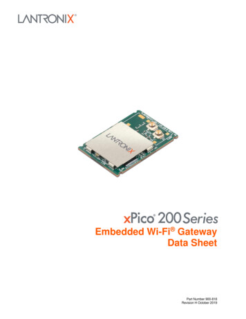
3: Pin and Pad DefinitionsTable 3-2 describes the xPico 200 Wi-Fi interface signal definition. The Signal Name columnidentifies the signal pin being described while the Primary Function column providesdefinitions of the signal pin depending upon the member of the xPico 200 family being used.Differentiating the signal pins is beneficial when using multiple xPico 200 device types on asingle platform.Figure 3-1 xPico 200 Edge Connector Pin & Signal LocationANT2WI-FI DIVERSITY(or BLUETOOTH)ANT12X U.FL WI-FIxPico 200 Series Embedded Wi-Fi Gateway Data Sheet16
Table 3-1: xPico 200 Edge Connector Signal DescriptionsPinSignalPinSignal1GND23.3V3USB D 43.3V5USB D-6SYS LED7GND8NC9SDIO SCK/SPI CLK (slave)10NC11SDIO CMD/SPI MOSI (slave)12USB H/D SEL13SDIO DATA0/SPI MISO (slave)14SDIO MODE/SPI SLAVE MODE15SDIO DATA1/SPI IRQ (slave)16CP9/LED17SDIO DATA218GND19SDIO DATA3/SPI CS (slave)20WAKE21NC22UART TXD23DEFAULT#32UART RXD33GND34UART RTS35TDO36UART CTS37TDI38TRST39GND40CP8/CS (master)41TCK42CP7/SCK (master)43TMS44CP4/MOSI (master)45GND46CP3/MISO (master)47RMII MDC48CP2/INT (master)49RMII MDIO50CP151GND52RESET#53RMII RXD154I2C2 CLK55RMII RXD056I2C2 DATA57GND58CP5/I2C DATA59NC60CP6/I2C CLK61RMII CLK62CP10/PWM63GND64NC65RMII RXDV66RSVD CP1267RMII TXEN68RSVD CP1169GND70RMII RST71RMII TXD1723.3V73RMII TXD0743.3V75GNDxPico 200 Series Embedded Wi-Fi Gateway Data Sheet17
Figure 3-2 xPico 200 PCB Interface Pin & Signal LocationxPico 200 Series Embedded Wi-Fi Gateway Data Sheet18
Table 3-2: xPico 200 PCB Interface Signal DescriptionsSignal NamePrimary FunctionxPico 200SMT PinEdgeConnectorPinGNDSignal Ground11SDCK/SPI CLK (slave)SDIO Clock/SPI SlaveClock2SDCMD/SPI MOSI (slave)SDIO CMD/SPI MasterOut-Slave In3SDIO0/SPI MISO (slave)SDIO Data 0/SPI MasterIn-Slave Out4SDIO1/SPI IRQ (slave)SDIO Data 1/SPI SlaveInterrupt5SDIO2SDIO Data 26SDIO3/SPI CS (slave)SDIO Data 3/SPI Slavechip select7CP3/MISO (master)Configurable I/O- SPIMISO8CP4/MOSI (master)Configurable I/O-SPIMOSI9CP7/SCK (master)Configurable I/O-SPIClock10CP8/CS (master)Configurable I/O-SPI ChipSelect11CP2/INT (master)Configurable I/O-SPIinterrupt input12I2C Data 2I2C Bus 2 dataI2C Clock 2DriverStrength98 mA118 mA138 mA151719468 mA8 mA8 mA8 mA448 mA428 mA408 mA488 mA13568 mAI2C Bus 2 clock14548 mACP5/I2CDATA*Configurable I/OI2CDATA588 mA15CP6/I2CCLK*Configurable I/O-I2CCLK16608 mAWAKEToggle signal from low tohigh to WAKE fromSLEEP or Power downstate. This pin must bepulled high with a 100Kohm resistor.Note: signal is noisesensitive. Filter as closeas possible to module pin.1720GNDSignal Ground187USB USB Port Positive pin193USB-USB Port Negative pin205GNDSignal Ground2133CP9/PWM/LEDConfigurable I/O-PWM2216RMII TXD0RMII TXD0 transmitoutput2373xPico 200 Series Embedded Wi-Fi Gateway Data Sheet8 mA19
Signal NamePrimary FunctionxPico 200SMT PinEdgeConnectorPinRMII TXD1RMII TXD1 transmitoutput2471RMII CLKRMII interface clock2561USB H/DEV SELUSB Host/Device ModeSelectPull high for device modeon USBPull low for host mode onUSBConnect to ID pin of USBconnector2612RMII TXENRMII transmit enableoutput2767RMII RSTRMII reset output2870SDIO MODE/SPI SLAVE MODESDIO Master/Slave selectPull high for master modeon SDIO.Pull low for slave mode onSDIO/SPI.2914RMII RXDVRMII RX data valid input3065RMII RXD0RMII RXD0 receive input3155RMII RXD1RMII RXD1 receive input3253SYS LEDSystem status LED, activehigh336GNDSignal Ground3439MDCMDIO clock3547MDIOMDIO data3649CP10/PWMConfigurable I/O-PWM37628 mACP1Configurable I/O38508 mARESERVED1Reserved for future UARTRX output39RESERVED2Reserved for future UARTTX output40EXT RESET#Unit hardware reset,active low. Drive low for50ms to reboot unit.Signal should be drivenhigh or pulled high afterassertion. EXT RESET#is inactive during modulepower down (standby)state. Assert WAKEsignal to come out of lowpower states prior toasserting reset.4152CTS1Serial clear-to-send input4236xPico 200 Series Embedded Wi-Fi Gateway Data SheetDriverStrength66688 mA20
Signal NamePrimary FunctionxPico 200SMT PinEdgeConnectorPin4374VCCPower input. Must beconnected to 3.3V powersupply4472VCCPower input. Must beconnected to 3.3V powersupply452,4VCCPower input. Must beconnected to 3,3V powersupplyRTS1Serial ready-to-send (232)/ serial transmit enable(485) output46348 mARXD1Serial receive data input47328 mATXD1Serial transmit data output4822TMSJTAG TMS Input4943TCKJTAG Clock Input5041TDIJTAG Data Input5137TDOJTAG Data Output5235TRSTJTAG Reset Input5338GNDSignal Ground5445DEFAULTDrive low for 6 seconds orlonger to reset unit todefault settings.5723GNDSignal Ground5851GNDSignal Ground5957GNDSignal Ground6063GNDSignal Ground6169GNDSignal Ground6475GNDSignal Ground6518GNDSignal Ground66Signal Ground67,68,69,70,71,72,73,74,75GND PADSDriverStrengthNote1: The current module supports an external 10/100 Mbps Ethernet PHY via the RMII interface.Note2: The logic IO pins are 3.3V tolerant.Note3: SMT Pins 67 to 75 are the ground pads under the module. These pads must be connected toground. These pads also provide thermal relief for the module. It is recommended that multiple vias foreach pad be used to connect the ground pads to the ground plane. Please see the evaluation board layoutas a reference for the ground pad and multiple via in pad recommendation. Contact your local FAE or salessupport for the evaluation kit artwork.Note 4: All unused IO pins may be left floating, except for the required straps on pins 17, 26, and 29.Note 5: Asterisk (*) indicates feature available in a future release. Contact your local sales representativefor availability.xPico 200 Series Embedded Wi-Fi Gateway Data Sheet21
4: InterfacesThe xPico 200 module offers a number of interfaces to allow for easy connectivity to themodule. These include 10/100 Mbps Ethernet MAC with RMII, UART for asynchronous serialcommunication, SPI Master and SPI Slave for synchronous formatted data, and USB interface.EthernetThe xPico 200 module has an integrated 10/100 Mbps Ethernet MAC and with an RMIIinterface. External PHY, magnetics and RJ45 are required for connection to a standardEthernet network. See the xPico 200 Series Embedded Wi-Fi Gateway Integration Guideavailable at https://www.lantronix.com/products/xpico-200/ for more details.UART The xPico 200 module supports one UART interface The UART supports asynchronous data rate up to 4 Mbps, with Odd/Even parity, and 1& 2 stop bits Software flow control (Xon, Xoff) Operational mode as a DTE device UART supports TX, RX, RTS, CTS (hardware flow control)Table 4-1: xPico 200 UART Signal DefinitionsPinNameDescriptionSMT PinEdge Conn. PinTXD1Serial transmit data output4822RTS1Serial ready-to-send/serial transmit enable output4634RXD1Serial receive data input4732CTS1Serial clear-to-send input4236xPico 200 Series Embedded Wi-Fi Gateway Data Sheet22
USB Host InterfaceTable 4-2: xPico 200 USB Host Interface Signal DefinitionsPin NameDescriptionSMT PinEdgeConn. PinSignalRequirementType AUSBHostConn.PinUSB /HHSDPBUSB HS Host Port APositive pin193Route as 90ohmdifferentialpair3USB-/HHSDPMUSB HS Host Port ANegative pin205Route as 90ohmdifferentialpair25V (Usersupplied)5V power for USB connectorCurrent limitto 500 mA perport1GroundSignal GroundGroundGroundGround plane4USB H/D SELUSB Host/Device ModeSelect2612Pull low forhost mode.Connect to IDpin of USBconnector ifusing A/B orType CconnectorUSB HostPower Enable(CP2)Output to enable externalUSB power switch for hostport connector (Useconfigurable CP2)1248Pull high forHost ModeUSB Host Port
xPico 200 Series Embedded Wi-Fi Gateway Data Sheet 7 1: Functional Description Overview The Lantronix xPico 200 series of embedded IoT gateways is one of the smallest and most highly integrated industrial Wi-Fi , Ethernet and Bluetooth combo solutions, allowing you to deliver and manage secure connected products without added complexity and risk.