Transcription
PD-T824XTrustedTrusted Power SystemProduct OverviewThe Trusted Power System is a high density flexible power supply designed to convert main linevoltages of either 110 Vac or 240 Vac. Outputs are either 24 Vdc for Trusted product or 28 Vdcadjustable field power.The Trusted Power System consists of a 1U Power Shelf with mechanical support, containing up tothree 750 W Power Packs. The Power Packs load share in configurations using one or more PowerShelves. Each Power Pack has an individual supply connection via a mechanically retained IEC 60320type connector. Each Power Shelf can supply 2250 W of power or 1500 W with n 1 redundancyfrom a single source. Multiple units can be connected for further capacity or redundancyrequirements.Diagnostic information of Power Pack status is provided via the Power Port, which connects to therear of the Power Shelf. This device monitors input and output conditions and reports out of rangefaults and over-temperature/fan failure using relay contacts. The Power Port also allows connectionof the optional rack mounted Power Controller for live configuration of output voltage and current,monitoring up to 12 Power Packs in 4 Power Shelves.Features: Redundant and n 1 configurations. Hot replaceable Power Packs. Current sharing. Current limiting. Power factor correction. Diagnostic contacts. Configurable output voltage. Input/output fail diagnostics per Power Pack.Rockwell Automation Publication PD-T824XIssue 11
TrustedPD-T824XPage intentionally left blankRockwell Automation Publication PD-T824XIssue 11
Trusted Power SystemPREFACEPREFACEIn no event will Rockwell Automation be responsible or liable for indirect or consequential damagesresulting from the use or application of this equipment. The examples given in this manual areincluded solely for illustrative purposes. Because of the many variables and requirements related toany particular installation, Rockwell Automation does not assume responsibility or reliability foractual use based on the examples and diagrams.No patent liability is assumed by Rockwell Automation, with respect to use of information, circuits,equipment, or software described in this manual.All trademarks are acknowledged.DISCLAIMERIt is not intended that the information in this publication covers every possible detail about theconstruction, operation, or maintenance of a control system installation. You should also refer toyour own local (or supplied) system safety manual, installation and operator/maintenance manuals.REVISION AND UPDATING POLICYThis document is based on information available at the time of its publication. The documentcontents are subject to change from time to time. The latest versions of the manuals are available atthe Rockwell Automation Literature Library under "Product Information" information "CriticalProcess Control & Safety Systems".TRUSTED RELEASEThis technical manual applies to Trusted Release: 3.6.1.LATEST PRODUCT INFORMATIONFor the latest information about this product review the Product Notifications and Technical Notesissued by technical support. Product Notifications and product support are available at the RockwellAutomation Support Centre athttp://rockwellautomation.custhelp.comAt the Search Knowledgebase tab select the option "By Product" then scroll down and select theTrusted product.Some of the Answer ID’s in the Knowledge Base require a TechConnect Support Contract. For moreinformation about TechConnect Support Contract Access Level and Features please click on thefollowing nswers/detail/a id/50871This will get you to the login page where you must enter your login details.IMPORTANTA login is required to access the link. If you do not have an account then you can create oneusing the "Sign Up" link at the top right of the web page.Rockwell Automation Publication PD-T824XIssue 11i
PREFACETrusted Power SystemDOCUMENTATION FEEDBACKYour comments help us to write better user documentation. If you discover an error, or have asuggestion on how to make this publication better, send your comment to our technical supportgroup at http://rockwellautomation.custhelp.comiiIssue 11Rockwell Automation Publication PD-T824X
Trusted Power SystemPREFACESCOPEThis manual specifies the maintenance requirements and describes the procedures to assisttroubleshooting and maintenance of a Trusted system.WHO SHOULD USE THIS MANUALThis manual is for plant maintenance personnel who are experienced in the operation andmaintenance of electronic equipment and are trained to work with safety systems.SYMBOLSIn this manual we will use these notices to tell you about safety considerations.SHOCK HAZARD: Identifies an electrical shock hazard. If a warning label is fitted, itcan be on or inside the equipment.WARNING: Identifies information about practices or circumstances that can causean explosion in a hazardous environment, which can cause injury or death,property damage or economic loss.ATTENTION: Identifies information about practices or circumstances that can causeinjury or death.CAUTION: Identifies information about practices or circumstances that can causeproperty damage or economic loss.BURN HAZARD: Identifies where a surface can reach dangerous temperatures. If awarning label is fitted, it can be on or inside the equipment.This symbol identifies items which must be thought about and put in place whendesigning and assembling a Trusted controller for use in a Safety InstrumentedFunction (SIF). It appears extensively in the Trusted Safety Manual.IMPORTANTIdentifies information that is critical for successful application and understanding ofthe product.NOTEProvides key information about the product or service.TIPTips give helpful information about using or setting up the equipment.Rockwell Automation Publication PD-T824XIssue 11iii
PREFACETrusted Power SystemWARNINGS AND CAUTIONSWARNING: EXPLOSION RISKDo not connect or disconnect equipment while the circuit is live or unless the area isknown to be free of ignitable concentrations or equivalentAVERTISSEMENT - RISQUE D’EXPLOSIONNe pas connecter ou déconnecter l’équipement alors qu’il est sous tension, sauf sil’environnement est exempt de concentrations inflammables ou équivalenteMAINTENANCEMaintenance must be carried out only by qualified personnel. Failure to follow theseinstructions may result in personal injury.CAUTION: RADIO FREQUENCY INTERFERENCEMost electronic equipment is influenced by Radio Frequency Interference. Cautionshould be exercised with regard to the use of portable communications equipmentaround such equipment. Signs should be posted in the vicinity of the equipmentcautioning against the use of portable communications equipment.CAUTION:The module PCBs contains static sensitive components. Static handling precautionsmust be observed. DO NOT touch exposed connector pins or attempt to dismantle amodule.ivIssue 11Rockwell Automation Publication PD-T824X
Trusted Power SystemPREFACEISSUE RECORDIssueDate1Aug 052Sep 05CommentsFormat / Power ControllerSect 5 Description3Feb 06Fault relay details added4Aug 06Corrections5Apr 07Inrush current details added6Nov 07Current sharing7Sep 08TC-323 clarification8Dec 08Current sharing with low loads9Apr 12Table 5 change10Sep 15Rebranded and reformatted with corrections to the OperatingTemperature and Relative Humidity Range statements in theSpecification Section.11Apr 16Document Updated to incorporate IEEE standards and to correcttypographical errorsRockwell Automation Publication PD-T824XIssue 11v
PREFACETrusted Power SystemPage intentionally left blankviIssue 11Rockwell Automation Publication PD-T824X
Trusted Power SystemTable of ContentsTable of Contents1.Product Range . 32.Description . 53.Power Shelf Specification . 73.1.3.2.3.3.3.4.3.5.Input Connector . 7Output Connector . 8Current Sharing . 8Interface Connector . 8Stacked-up Assembly . 114.Power Pack Specifications . 134.1.Power Pack Features . 134.1.1. Indicators . 134.1.2. Over-current Protection . 144.2.Input Specification . 144.3.Line Harmonics . 154.4.Efficiency and Power Factor vs. Input Voltage at Full Load . 154.5.Output Specification . 154.6.Environmental Characteristics . 174.7.Power Pack Hot Replacement . 185.Power Port . 195.1.5.2.General Description . 19Circuit Description . 215.2.1. Supply . 215.2.2. DC Alarms . 215.2.3. AC Alarms . 215.2.4. Jumpers . 225.3.Mechanical . 225.3.1. Pin-out CON 1, CON 2 . 225.3.2. Pin-out CON 3 . 245.3.3. Fault Relay Technical Specifications . 256.Power Controller . 276.1.Power Sequencing. 28Rockwell Automation Publication PD-T824XIssue 111
Table of ContentsTrusted Power System7.Power Shields . 298.Power Shelf Interconnect . 319.Power System Specification . 332Issue 11Rockwell Automation Publication PD-T824X
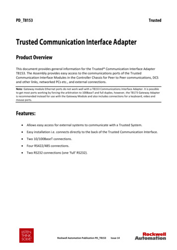
Trusted Power System1. Product Range1. Product RangeCatalogue No.Product nameDescriptionT8240Power Shelf19 inch x 1U chassis for up to 3 Power Packs.Includes Power Port 10-way cable connector, 3 offmains plugs and retaining clips.T8231Power Pack 24 Vdc750 W, universal input, 24 Vdc out.T8232Power Pack 28 Vdc750 W, universal input, 28 Vdc out.T8243Power PortPlug in diagnostic interface 10-way cableconnector.T8234Power ControllerFor live adjustment of output voltage. 19 inch x 1U.1 x 5 way ribbon cable.T8235Power ShieldCovers unused Power Pack positions.TC-323Power ShelfInterconnect1 x 5 way ribbon cable for current sharing betweenshelves and connection to a Power Controller.T8247Power Shelf supportbracketsA pair of brackets that can support up to 4 PowerShelves.Table 1 T824X Power System Product RangeFigure 1 Front View - Power Shelf with Power PacksRockwell Automation Publication PD-T824XIssue 113
1. Product RangeTrusted Power SystemPage intentionally left blank4Issue 11Rockwell Automation Publication PD-T824X
Trusted Power System2. Description2. DescriptionA pair of brackets mounted in to a 19 inch frame supports up to 4 Power Shelves.Power Packs are slotted into the 1U Power Shelf with the first Power Pack in the right handslot, as shown in Figure 2. Each Power Pack provides 750 W (31.25 A at 24 Vdc) to the DCoutput on the Power Shelf.The standard AC input connection to the Power Shelf is through IEC 60320 type connectorsrated at 10 A/250 Vac in Europe/Asia and 15 A/120 Vac in North America.Output terminal blocks on each Power Shelf have three M4 screw connections. Ring typeconnectors should be used when connecting from the Power Shelf to system powerdistribution busbars.The Power Port plugs into the back of the Power Shelf and requires a 24 V supply. ThePower Port can provide monitoring and control via a 25 way D connector when connectedto a Power Controller. A separate connector (CON3) provides DC and AC fail contacts. Whenmore than one Power Shelf is used, Power Ports are linked using a Power Shelf Interconnectribbon cable to enable current sharing.Spare slots in the Power Shelf are normally covered by Power Shields and the appropriatefault relays are linked on the Power Port.The 824X system includes an optional 1U Power Controller that is connected via the PowerPort, using a TC-323 Power Shelf Interconnect cable, and allows online setting of outputvoltage. The Power Controller can monitor up to 12 Power Packs in 4 Power Shelves. EachPower Shelf is identified by the Power Controller by selecting addresses on the Power Portas described in paragraph 5.2.4.Unused slots in the 4U brackets may be used for other equipment or fitted with blankingplates.Unused connectors on the TC-323 cable should be tied back and left unused.Rockwell Automation Publication PD-T824XIssue 115
2. DescriptionTrusted Power SystemPage intentionally left blank6Issue 11Rockwell Automation Publication PD-T824X
Trusted Power System3. Power Shelf Specification3. Power Shelf SpecificationThe Power Shelf is designed to operate as a key element in a complete distributed PowerSystem.This Power Shelf can house up to three Power Packs, provides physical protection and anumber of alarm and control features.The Power Shelf can supply up to 1500 W of n 1 redundant power or up to 2250 W of totalpower depending on configuration of Power Packs. Four stacked Power Shelves can provideup to 9000 W total power.Figure 2 1U Power Shelf Mechanical Outline3.1. Input ConnectorThe Power Shelf can be used with any standard global line voltages. The standard AC inputconnection to the Power Shelf is through three clip retained IEC 60320 type connectorsrated at 10 A / 250 Vac in Europe/Asia and 15 A /120 Vac in North America.Rockwell Automation Publication PD-T824XIssue 117
3. Power Shelf SpecificationTrusted Power System3.2. Output ConnectorThe Power Shelf has two terminal blocks for DC output (each with three M4 screws). The V and V- are floating with respect to frame GND, either of which can be connected to GND asrequired.3.3. Current SharingNote: If there is a low load on a Power Shelf (less than 2 A per Power Pack) then the current sharing circuit maynot work correctly and ‘PWR OK’ LED may not illuminate on the Power Packs.In systems where more than one Power Shelf is being used, Shelves should connect their CSterminals by using a Power Shelf Interconnect cable TC-323. This ensures that the PowerShelves current share.Do not connect the TC-323 cable between ‘A’ and ‘B’ supplies or between two sets ofShelves which connect to separate busbars. The supplies will attempt to share currentbetween the two busbars, which may damage the power packs and Shelves’ sensing circuits.Unused connectors on the TC-323 cable should be tied back and left unused.3.4. Interface ConnectorThe Power Shelf has an optional DSB, 25-pin, female interface connector on the back. ThePower System can be monitored and controlled through this interface, by a PowerController, using a Power Shelf Interconnect. AC and DC fail alarms are available from aseparate connector on the Power Port.8Pin NumberSignal NameDescription1DC Fail 22A2I2C address bit 23A3I2C address bit 34ON SYNC5SDAI2C Serial data bus6SCLI2C Clock7NCNo connection8On/Off 19OTP 1DC Fail signal of the second Power Pack *Not UsedRemote on off control for the first Power Pack - Not UsedFan Fail or Over-Temperature signal for the first Power Pack *Issue 11Rockwell Automation Publication PD-T824X
Trusted Power System3. Power Shelf SpecificationPin NumberSignal NameDescription10On/Off 211V aux12DC Fail 1DC Fail signal of the first Power Pack *13AC Fail 3AC Fail signal of the third Power Pack *14OTP 315DC Fail 3DC Fail signal of the third Power Pack *16INT BUSNot used *17AC Fail 1AC Fail signal of the first Power Pack *18On/Off 3Remote on off control for third Power Pack - Not Used19SRTN20RS-21OTP 222RS 23AC Fail 2AC Fail signal of the second Power Pack *24CSA single wire interface for current sharing25V-V-Remote on off control for the second Power Pack - Not UsedNot UsedFan Fail or Over-Temperature signal of the third Power Pack *Signal return and V aux returnRemote sense for VFan Fail or Over-Temperature signal of the second Power Pack *Remote sense for V * opto-isolated, open collectorTable 2 Pin Assignment of the Interface ConnectorRefer to Figure 2 1U Power Shelf Mechanical Outline for the locations of Power Pack 1, 2and 3.Rockwell Automation Publication PD-T824XIssue 119
3. Power Shelf SpecificationTrusted Power SystemFigure 3 Interface Connector10Issue 11Rockwell Automation Publication PD-T824X
Trusted Power System3. Power Shelf Specification3.5. Stacked-up AssemblyFigure 4 4U Stacked-up AssemblyRockwell Automation Publication PD-T824XIssue 1111
3. Power Shelf SpecificationTrusted Power SystemPage intentionally left blank12Issue 11Rockwell Automation Publication PD-T824X
Trusted Power System4. Power Pack Specifications4. Power Pack SpecificationsThe Power Pack is specifically designed to operate as an integral part of a completedistributed Power System.A full complement of protection, alarm and control features has been incorporated into thePower Pack to provide versatility for use in many applications.Power Packs can be inserted and removed when live, allowing ‘hot-swap’ of Power Packs.They are secured using a physical latch on the front of the Power Pack which is pushed up torelease or connect the Power Pack into the Power Shelf.Figure 5 Power Pack Outline Drawing. Dimensions mm (inches)4.1. Power Pack Features4.1.1.IndicatorsThe Power Pack has two indicators on the front: AC OK: The LED is green if the input voltage is within limits. PWR OK: The LED is green if the Power Pack is healthy and within operating limits. Ifa fault occurs with the power supply or a fan, the LED is amber.Rockwell Automation Publication PD-T824XIssue 1113
4. Power Pack Specifications4.1.2.Trusted Power SystemOver-current ProtectionThe over-current protection limits the output current in the event of an overload. There aretwo overload circumstances: If the load is increased steadily a single Power Pack compensates by derating thevoltage, hence at 40 A (the specification limit) the voltage is derated to 18.75 V. Thisderated voltage is on the limit of the Trusted System Modules’ specification.Note: This gradual increase is not typical of a system fault. If 2 4V is maintained over a rapid current rise, the over-current protection will causethe power supply to go to protective shutdown when 35 A is reached. This rapidincrease is more typical of a fault situation in a system.A switched 125 % overload of the maximum output will cause the power supplies to reducetheir output voltage for a period of 700 ms after which they will go into protectiveshutdown. After 3 seconds the power supplies will attempt to restart, but due to theoverload they shutdown again.In extreme overload conditions a power supply will provide 115 A for up to 200 ms.4.2. Input SpecificationParameterMinTypeMaxUnitInput Voltage90264VacInput Frequency4763HzInrush Current (peak) per Pack50A 25Input CurrentPower Factor0.20.95Input Leakage CurrentA0.99Full loadNo loadNo load 50 % of full load1.7mALighting Surge and Transients(damage free operation)Hold Up TimeCondition264 Vac, 50 HzIEC 61000-4-5 Level 3IEC 61000-4-4 Level 320msEMC (conducted)At 600 WCISPR22 Class B,EN 55022 Class B, with 3dBmarginTable 3 Input Specification14Issue 11Rockwell Automation Publication PD-T824X
Trusted Power System4. Power Pack Specifications4.3. Line HarmonicsActive power factor correction circuitry ensures that this Power Pack meets therequirements of IEC 61000-3-2.4.4. Efficiency and Power Factor vs. Input Voltage at Full LoadInput voltageEfficiency(Typical)Power Factor(Typical)90 Vac78 %0.99100 Vac79 %0.99110 Vac80 %0.99120 Vac81 %0.98180 Vac82 %0.98220 Vac83 %0.98240 Vac83 %0.98264 Vac84 %0.98Table 4 Efficiency and Power Factor vs. Input Voltage at Full LoadWhen using this table to calculate cable feed requirements, allow, at a minimum, an extra3 % for variations between units. Actual measured results will depend upon the harmoniccontent of the input voltage waveform.4.5. Output SpecificationParameterMin Type MaxUnit NoteV OUT set point:T823124VdcT823228VdcRegulation (line, load,temperature and set point)Remote-sense DropRockwell Automation Publication PD-T824X-22%0.5VdcIssue 11Measured at remote sensebetween pins 20 and 22 ofinterface15
4. Power Pack SpecificationsTrusted Power SystemParameterMin Type MaxUnit NoteI OUT (rated):T8231 (24 V OUT )031.25Adc 750 W maximumT8232 (28 V OUT )026.78Adc 750 W maximumRipple (20 MHz bandwidth)150mVp-pNoise (20 MHz bandwidth)300mVp-p Under any load conditionsTransmission Noise (C message)45dBmc10100msRise from 10 % to 90 % of finaloutput level (resistive load)2932VdcReset by cycling ac input, on/off,or reinsertion40AAdc2% 3.2AOutput Rise TimeOver-voltage ProtectionOutput Current Limit (Steadystate)Transient ResponseVoltage Range-2Active Current Sharing Differential25 % step load transient with slewrate 0.1A/us within the rangefrom 25 % to 75 % of full loadSingle-wire current share at fullloadEfficiencyAt full load, 120 Vac withORing diode8081%At full load, 264 Vac withORing diode83.584%ORing diodeReserve Output CurrentProtectionStart-up Delay1.3Turn-on Delay2s250msMeasured from application ofvalid AC voltageMeasured from DC on/offTable 5 Output Specification16Issue 11Rockwell Automation Publication PD-T824X
Trusted Power System4. Power Pack Specifications4.6. Environmental CharacteristicsParameterMinStorage Temperature-40OperatingTemperature (note1)TypeUnit Note-85 C-60 C47520AcousticsMax1. Derate at 1.333 %/ C, 45 C to 50 C2. Derate at 4.667 %/ C, 50 C to 60 CdBa Sound Pressure Level at 1 mRelative ed at 2 C/304 m above 2438 mElectro StaticDischargeIEC 61000-4-2 Level 3 stand-aloneElectromagneticImmunity (error free)IEC 61000-4-3 Level 2 stand-aloneIsolation VoltageMTBF3000Vac Primary to Secondary1500Vac Primary to chassis GND1500Vac Secondary to chassis GND4 x 105hours @110 Vinput 80 % load, T A 30 oCVibrationMeet IEC 60068-2-6ShockMeet IEC 60068-2-27Weight2.3kgTable 6 Environmental CharacteristicsFigure 6 Operation Derating CurveRockwell Automation Publication PD-T824XIssue 1117
4. Power Pack SpecificationsTrusted Power System4.7. Power Pack Hot Replacement1. Plug in slowly and smoothly.2. Make sure the first set of pins are contacted – the AC OK LED will illuminate.3. Push fully home - the PWR OK LED will illuminate.Figure 7 Power Pack Hot Replacement18Issue 11Rockwell Automation Publication PD-T824X
Trusted Power System5. Power Port5. Power Port5.1. General DescriptionThe Power Port is an accessory that fits onto the rear of the Power Shelf. It converts alarmsignals produced by the Power Packs and Power Shelf into volt-free alarm contacts for useby the system. It consists of a printed circuit board (PCB) fitted with connectors, relays andmiscellaneous electronic components. The shape and size of the Power Port is shown inFigure 8 Power Port Outline Drawings.The alarm contacts are made available on a connector for ease of wiring into the system.The system provides a supply for the Power Port, which is wired to the same connector. Theconnector pin-outs are shown in section 5.3.The Power Shelf is fitted with a 25 way D female connector to which the Power Portconnects. The Power Port is retained to the Power Shelf by means of the Dsub jack screws.The Power Port is fitted with a 25 way D female connector to allow the Power Shelfconnectivity to be extended to a Power Controller, or to other Shelves to current share,using a Power Shelf Interconnect cable.The Power Controller is powered from the Power Port 24 V supply via pin 7, whenconnecting CON 2 on the Power Port to the Power Controller.Rockwell Automation Publication PD-T824XIssue 1119
5. Power PortTrusted Power SystemFigure 8 Power Port Outline Drawings20Issue 11Rockwell Automation Publication PD-T824X
Trusted Power System5. Power Port5.2. Circuit DescriptionThe circuit is split into four functional sections: supply, dc alarms, ac alarms and jumpers.5.2.1.SupplyThe 24 V supply is connected to CON3 pins 1 and 6. The supply should be fused close to itssource, using a 500 mA F-rated fuse. It is nevertheless protected by a non-replaceable fuseon the Power Port. The 24 V is regulated down to 5 V with decoupling provided. The 5 V isused to supply the low voltage electronics. The 24 V is used to supply the relays and isconnected through CON2 to power the optional Power Controller. Pins 19, 20 and 25 of theinterface are linked within the Power Port.5.2.2.DC AlarmsCON1 is the 25 way D male interface to the Power Shelf. The Power Pack and Power Shelfalarm outputs are derived from here. There are two DC alarms per Power Pack: DCFAIL (DCoutput fail) and OTP (over-temperature protection). The Power Port ORs together DCFAILand OTP to give one DC fail alarm. If either alarm triggers, the corresponding relayde-energises.Each relay operates a volt-free contact. These are closed when healthy (relay energised) andopen in alarm.5.2.3.AC AlarmsIn a similar manner, each Power Pack generates an AC alarm. When an alarm is triggered,the corresponding relay de-energises. Each relay operates a volt-free contact. These areclosed when healthy (relay energised) and open in alarm.Fault ConditionOutputOK LEDOTP AlarmAC Fail AlarmDC Fail AlarmDC OutputNo faultGreenLowClosedClosedONFan locked rotorAmberLowClosedClosedONSecondary overtemperatureAmberHighClosedOpenOFFPrimary overtemperatureOffHighClosedOpenOFFAC Feeder FailOffLowOpenOpenOFFTable 7 Alarm ConditionsRockwell Automation Publication PD-T824XIssue 1121
5. Power Port5.2.4.Trusted Power SystemJumpersThere are two jumpers, J1 and J2.J1 and J2 set the Power Shelf address lines for the I2C control bus. With J1 and J2 fitted thePack addresses are 1, 2 and 3, which is the default. Other addresses may be set by removingone or both of J1 and J2, up to 4 Shelves worth (or 12 Power Packs).Power 4removedremovedTable 8 Power Shelf Addressing5.3. Mechanical5.3.1.Pin-out CON 1, CON 2CON 1 on the Power Port connects to the Power Shelf. The pin-out details are shown inTable 2 Pin Assignment of the Interface Connector.CON 2 is used to connect to other Power Shelves to current share or to connect to a PowerController.NumberSignal NameDescription1234ON SYNCNot Used5SDAI2C Serial data bus6SCLI2C Clock724vSupply from Power Port822Issue 11Rockwell Automation Publication PD-T824X
Trusted Power SystemNumber5. Power PortSignal NameDescription910111213141516INT BUSNot Used171819SRTNSignal return and V aux return *20RS-Remote sense for V- *RS Remote sense for V CSA single wire interface for currentsharingV-V- *2122232425* linked within a Power PortTable 9 Connected Pins on CON 2Rockwell Automation Publication PD-T824XIssue 1123
5. Power Port5.3.2.Trusted Power SystemPin-out CON 3Pin1Description 24V system supply2/3DCFAIL 13/4DCFAIL 24/5DCFAIL 360V system supply return7/8ACFAIL 38/9ACFAIL 29/10ACFAIL 1Table 10 Connector 3 Pin-outCON 3 provides volt-free alarm contacts as detailed in section 5.2.2 and 5.2.3 for use by thesystem. These are made available on a connector for ease of wiring into the system.CON 3 connector cable block is Weidmuller type BLZF3.5/10.The relays are energised (contacts closed) when a PSU is
Trusted Power System . Product Overview . The Trusted Power System is a high density flexible power supply designed to convert main line voltages of either 110 Vac or 240 Vac. Outputs are either 24 Vdc for Trusted product or 28 Vdc adjustable field power. The Trusted Power System consists of a 1U Power Shelf with mechanical support .