Transcription
PD-T8800TrustedTrusted 40 Channel 24 Vdc Digital Input FTAProduct OverviewThe Trusted Field Termination Assembly (FTA) - 24 Vdc Digital Input T8800 is designed to act as themain interface between a field device generating a digital signal and the Trusted TMR 24 Vdc DigitalInput Module T8403.Features: 40 input channels per FTA. Industry standard field device connections (2-wire). Standard DIN rail compatibility. Simple installation and connection. 24 Vdc operation. SmartSlot connection for ‘one to many’ hot replacement of input modules. Fused field power supply per channel. On-board Light Emitting Diode (LED) indication of field power supply integrity.Rockwell Automation Publication PD-T8800Issue 6
TrustedPD-T8800Page intentionally left blankRockwell Automation Publication PD-T8800Issue 6
Trusted 40 Channel 24 Vdc Digital Input FTAPREFACEPREFACEIn no event will Rockwell Automation be responsible or liable for indirect or consequential damagesresulting from the use or application of this equipment. The examples given in this manual areincluded solely for illustrative purposes. Because of the many variables and requirements related toany particular installation, Rockwell Automation does not assume responsibility or reliability foractual use based on the examples and diagrams.No patent liability is assumed by Rockwell Automation, with respect to use of information, circuits,equipment, or software described in this manual.All trademarks are acknowledged.DISCLAIMERIt is not intended that the information in this publication covers every possible detail about theconstruction, operation, or maintenance of a control system installation. You should also refer toyour own local (or supplied) system safety manual, installation and operator/maintenance manuals.REVISION AND UPDATING POLICYThis document is based on information available at the time of its publication. The documentcontents are subject to change from time to time. The latest versions of the manuals are available atthe Rockwell Automation Literature Library under "Product Information" information "CriticalProcess Control & Safety Systems".TRUSTED RELEASEThis technical manual applies to Trusted Release: 3.6.1.LATEST PRODUCT INFORMATIONFor the latest information about this product review the Product Notifications and Technical Notesissued by technical support. Product Notifications and product support are available at the RockwellAutomation Support Centre athttp://rockwellautomation.custhelp.comAt the Search Knowledgebase tab select the option "By Product" then scroll down and select theTrusted product.Some of the Answer ID’s in the Knowledge Base require a TechConnect Support Contract. For moreinformation about TechConnect Support Contract Access Level and Features please click on thefollowing nswers/detail/a id/50871This will get you to the login page where you must enter your login details.Rockwell Automation Publication PD-T8800Issue 6i
PREFACEIMPORTANTTrusted 40 Channel 24 Vdc Digital Input FTAA login is required to access the link. If you do not have an account then you can create oneusing the "Sign Up" link at the top right of the web page.DOCUMENTATION FEEDBACKYour comments help us to write better user documentation. If you discover an error, or have asuggestion on how to make this publication better, send your comment to our technical supportgroup at http://rockwellautomation.custhelp.comiiIssue 6Rockwell Automation Publication PD-T8800
Trusted 40 Channel 24 Vdc Digital Input FTAPREFACESCOPEThis manual specifies the maintenance requirements and describes the procedures to assisttroubleshooting and maintenance of a Trusted system.WHO SHOULD USE THIS MANUALThis manual is for plant maintenance personnel who are experienced in the operation andmaintenance of electronic equipment and are trained to work with safety systems.SYMBOLSIn this manual we will use these notices to tell you about safety considerations.SHOCK HAZARD: Identifies an electrical shock hazard. If a warning label is fitted, itcan be on or inside the equipment.WARNING: Identifies information about practices or circumstances that can causean explosion in a hazardous environment, which can cause injury or death,property damage or economic loss.ATTENTION: Identifies information about practices or circumstances that can causeinjury or death.CAUTION: Identifies information about practices or circumstances that can causeproperty damage or economic loss.BURN HAZARD: Identifies where a surface can reach dangerous temperatures. If awarning label is fitted, it can be on or inside the equipment.This symbol identifies items which must be thought about and put in place whendesigning and assembling a Trusted controller for use in a Safety InstrumentedFunction (SIF). It appears extensively in the Trusted Safety Manual.IMPORTANTIdentifies information that is critical for successful application and understanding ofthe product.NOTEProvides key information about the product or service.TIPTips give helpful information about using or setting up the equipment.Rockwell Automation Publication PD-T8800Issue 6iii
PREFACETrusted 40 Channel 24 Vdc Digital Input FTAWARNINGS AND CAUTIONSWARNING: EXPLOSION RISKDo not connect or disconnect equipment while the circuit is live or unless the area isknown to be free of ignitable concentrations or equivalentAVERTISSEMENT - RISQUE D’EXPLOSIONNe pas connecter ou déconnecter l’équipement alors qu’il est sous tension, sauf sil’environnement est exempt de concentrations inflammables ou équivalenteMAINTENANCEMaintenance must be carried out only by qualified personnel. Failure to follow theseinstructions may result in personal injury.CAUTION: RADIO FREQUENCY INTERFERENCEMost electronic equipment is influenced by Radio Frequency Interference. Cautionshould be exercised with regard to the use of portable communications equipmentaround such equipment. Signs should be posted in the vicinity of the equipmentcautioning against the use of portable communications equipment.CAUTION:The module PCBs contains static sensitive components. Static handling precautionsmust be observed. DO NOT touch exposed connector pins or attempt to dismantle amodule.ivIssue 6Rockwell Automation Publication PD-T8800
Trusted 40 Channel 24 Vdc Digital Input FTAPREFACEISSUE RECORDIssueDateComments5Sep 05Format6Jun 16Rebranded and reformatted with correction to Relative Humidity Rangeand Operating Temperature statements in the Specification Section, alsocorrection of any typographical errorsRockwell Automation Publication PD-T8800Issue 6v
PREFACETrusted 40 Channel 24 Vdc Digital Input FTAPage intentionally left blankviIssue 6Rockwell Automation Publication PD-T8800
Trusted 40 Channel 24 Vdc Digital Input FTATable of ContentsTable of Contents1.Description . 32.Installation . 53.Associated Cable Selection . 74.Assembly Pinout Connections . 94.1.4.2.4.3.4.4.PWR TB Connections . 9TB3 (Auxiliary Input) Connections. 9TB2 (Field Terminals) Connections. 9SK1 and SK2 . 115.Specifications. 14Rockwell Automation Publication PD-T8800Issue 61
Table of ContentsTrusted 40 Channel 24 Vdc Digital Input FTAPage intentionally left blank2Issue 6Rockwell Automation Publication PD-T8800
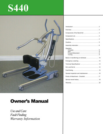
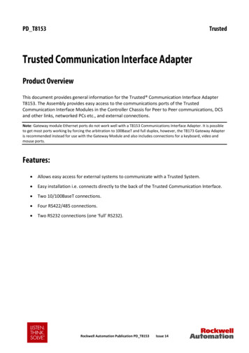
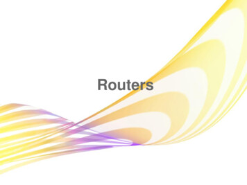
Trusted 40 Channel 24 Vdc Digital Input FTA1. Description1. DescriptionFigure 1 T8800 LayoutThe Trusted 40 Channel 24 Vdc Digital Input Field Termination Assembly T8800 providestermination for a maximum of 40 input channels from various types of field devices whichgenerate a digital input. Figure 2 below shows the configuration of a single channel.Figure 2 Single Channel SchematicThe supply for the field is derived from dual 24 Vdc feeds which are ‘commoned’ via diodeson the FTA. Indication of the presence of the power supply is provided by a green LED. Thesupply is then fed to each channel.The supply voltage to the field is fed via the 50 mA fuse. This effectively limits the current inthe field loop. The incoming signal (digital) from the field device is fed directly to the digitalinput module. Line monitoring components (if required) provide the necessary thresholdsused by the input module to detect the field loop/device status, i.e. open/short circuit,alarm etc.The cable linking the 40 channels on the input module to the FTA is terminated at the96-way socket SK1. SmartSlot (Version 1) signals from the module are connected to SK1. TheRockwell Automation Publication PD-T8800Issue 63
1. DescriptionTrusted 40 Channel 24 Vdc Digital Input FTASmartSlot connector is SK2 and is also a 96-way socket. This connector is not used whereSmartSlot Version 2 is employed within the Trusted System. The dual dc field power suppliesare connected to the FTA via a 5-way terminal block PWR TB. The input signals from thefield (40-off) are connected by 2-wire arrangements terminated on 12-off 3-way terminalblocks and 2-off 2-way.4Issue 6Rockwell Automation Publication PD-T8800
Trusted 40 Channel 24 Vdc Digital Input FTA2. Installation2. InstallationTrusted 40 Channel 24 Vdc Digital Input FTA T8800 is designed to be mounted on either ofthe TS32 or TS35 DIN rails in the horizontal or vertical positions as required.Rockwell Automation Publication PD-T8800Issue 65
2. InstallationTrusted 40 Channel 24 Vdc Digital Input FTAPage intentionally left blank6Issue 6Rockwell Automation Publication PD-T8800
Trusted 40 Channel 24 Vdc Digital Input FTA3. Associated Cable Selection3. Associated Cable SelectionRefer to the product descriptions detailed below:PD-TC000Trusted Power CablesPD-TC200Trusted I/O Companion Slot CablesPD-TC500Trusted I/O SmartSlot CablesRockwell Automation Publication PD-T8800Issue 67
3. Associated Cable SelectionTrusted 40 Channel 24 Vdc Digital Input FTAPage intentionally left blank8Issue 6Rockwell Automation Publication PD-T8800
Trusted 40 Channel 24 Vdc Digital Input FTA4. Assembly Pinout Connections4. Assembly Pinout Connections4.1. PWR TB ConnectionsPinService124 V-A224 V-B30V40V524 V (auxiliary supply for use when required)Table 1 PWR TB Connections4.2. TB3 (Auxiliary Input) ConnectionsPinService1Chan 0 (not configured)2Chan 41 (not configured)Table 2 TB3 Auxiliary Input Connections4.3. TB2 (Field Terminals) ConnectionsPin ServicePinService1Chan 1 24 Vdc field supply2Chan 1 signal from field3Chan 2 24 Vdc field supply4Chan 2 signal from field5Chan 3 24 Vdc field supply6Chan 3 signal from field7Chan 4 24 Vdc field supply8Chan 4 signal from field9Chan 5 24 Vdc field supply10Chan 5 signal from field11Chan 6 24 Vdc field supply12Chan 6 signal from fieldRockwell Automation Publication PD-T8800Issue 69
4. Assembly Pinout Connections10Trusted 40 Channel 24 Vdc Digital Input FTAPin ServicePinService13Chan 7 24 Vdc field supply14Chan 7 signal from field15Chan 8 24 Vdc field supply16Chan 8 signal from field17Chan 9 24 Vdc field supply18Chan 9 signal from field19Chan 10 24 Vdc field supply20Chan 10 signal from field21Chan 11 24 Vdc field supply22Chan 11 signal from field23Chan 12 24 Vdc field supply24Chan 12 signal from field25Chan 13 24 Vdc field supply26Chan 13 signal from field27Chan 14 24 Vdc field supply28Chan 14 signal from field29Chan 15 24 Vdc field supply30Chan 15 signal from field31Chan 16 24 Vdc field supply32Chan 16 signal from field33Chan 17 24 Vdc field supply34Chan 17 signal from field35Chan 18 24 Vdc field supply36Chan 18 signal from field37Chan 19 24 Vdc field supply38Chan 19 signal from field39Chan 20 24 Vdc field supply40Chan 20 signal from field41Chan 21 24 Vdc field supply42Chan 21 signal from field43Chan 22 24 Vdc field supply44Chan 22 signal from field45Chan 23 24 Vdc field supply46Chan 23 signal from field47Chan 24 24 Vdc field supply48Chan 24 signal from field49Chan 25 24 Vdc field supply50Chan 25 signal from field51Chan 26 24 Vdc field supply52Chan 26 signal from field53Chan 27 24 Vdc field supply54Chan 27 signal from field55Chan 28 24 Vdc field supply56Chan 28 signal from field57Chan 29 24 Vdc field supply58Chan 29 signal from field59Chan 30 24 Vdc field supply60Chan 30 signal from fieldIssue 6Rockwell Automation Publication PD-T8800
Trusted 40 Channel 24 Vdc Digital Input FTA4. Assembly Pinout ConnectionsPin ServicePinService61Chan 31 24 Vdc field supply62Chan 31 signal from field63Chan 32 24 Vdc field supply64Chan 32 signal from field65Chan 33 24 Vdc field supply66Chan 33 signal from field67Chan 34 24 Vdc field supply68Chan 34 signal from field69Chan 35 24 Vdc field supply70Chan 35 signal from field71Chan 36 24 Vdc field supply72Chan 36 signal from field73Chan 37 24 Vdc field supply74Chan 37 signal from field75Chan 38 24 Vdc field supply76Chan 38 signal from field77Chan 39 24 Vdc field supply78Chan 39 signal from field79Chan 40 2 4Vdc field supply80Chan 40 signal from fieldTable 3 TB2 (Field Terminal) Connections4.4. SK1 and SK2CBASmartSlot Link CSmartSlot Link BSmartSlot Link A3Chan 28 ( )Chan 14 ( )Chan 0 ( )4Chan 28 ( )Chan 14 ( )Chan 0 ( )5Chan 29 ( )Chan 15 ( )Chan 1 ( )6Chan 29 ( )Chan 15 ( )Chan 1 ( )7Chan 30 ( )Chan 16 ( )Chan 2 ( )8Chan 30( )Chan 16 ( )Chan 2 ( )90V0V0V10Chan 31 ( )Chan 17 ( )Chan 3 ( )11Chan 31 ( )Chan 17 ( )Chan 3 ( )12Rockwell Automation Publication PD-T8800Issue 611
4. Assembly Pinout ConnectionsTrusted 40 Channel 24 Vdc Digital Input FTACBA12Chan 32 ( )Chan 18 ( )Chan 4 ( )13Chan 32 ( )Chan 18 ( )Chan 4 ( )14Chan 33 ( )Chan 19 ( )Chan 5 ( )15Chan 33 ( )Chan 19 ( )Chan 5 ( )16Chan 34 ( )Chan 20 ( )Chan 6 ( )17Chan 34 ( )Chan 20 ( )Chan 6 ( )18Chan 35 ( )Chan 21 ( )Chan 7 ( )19Chan35 ( )Chan 21 ( )Chan 7 ( )200V0V0V21Chan 36 ( )Chan 22 ( )Chan 8 ( )22Chan 36 ( )Chan 22 ( )Chan 8 ( )23Chan 37 ( )Chan 23 ( )Chan 9 ( )24Chan 37 ( )Chan 23 ( )Chan 9 ( )25Chan 38 ( )Chan 24 ( )Chan 10 ( )26Chan 38 ( )Chan 24 ( )Chan 10 ( )27Chan 39 ( )Chan 25 ( )Chan 11 ( )28Chan 39 ( )Chan 25 ( )Chan 11 ( )29Chan 40 ( )Chan 26 ( )Chan 12 ( )30Chan 40 ( )Chan 26 ( )Chan 12 ( )31Chan 41 ( )Chan 27 ( )Chan 13 ( )32Chan 41 ( )Chan 27 ( )Chan 13 ( )Table 4 Connections SK1 and SK212Issue 6Rockwell Automation Publication PD-T8800
Trusted 40 Channel 24 Vdc Digital Input FTA4. Assembly Pinout ConnectionsPage intentionally left blankRockwell Automation Publication PD-T8800Issue 613
Trusted 40 Channel 24 Vdc Digital Input FTA5. Specifications5. SpecificationsVoltage Range18 Vdc to 32 VdcFuses40-off 50 mAMaximum Current (Field Supply)10 mAPower Consumption (Field Supply)0.25 WOperating Temperature0 C to 60 C ( 32 F to 140 F)Non-operating Temperature-25 C to 70 C (-13 F to 158 F)Relative Humidity range(operating, storage and transport)10 % – 95 %, non-condensingEnvironmental SpecificationsRefer to Document 552517DimensionsHeight111 mm (4.4 in)Width335 mm (13.2 in)Depth51 mm (2 in)WeightRockwell Automation Publication PD-T8800900 g (2 lb)Issue 614
1. Description Trusted 40 Channel 24 Vdc Digital Input FTA 4 Issue 6 Rockwell Automation Publication PD-T8800 SmartSlot connector is SK2 and is also a 96-way socket. This connector is not used where SmartSlot Version 2 is employed within the Trusted System. The dual dc field power supplies are connected to the FTA via a 5-way terminal block PWR TB.