Transcription
Rockwell AutomationProcess HMI Style GuideWhite Paper
Table of Contents1Introduction . 51.1Before You Begin . 51.2Additional Resources . 62Functional Description of HMI Components . 63Display Levels. 743.1Level 1 Displays: Process Overview . 83.2Level 2 Displays: Process Unit Operating Graphics . 93.3Level 3 Displays: Process Detail Displays. 103.4Level 4 Displays: Process Support and Diagnostics Displays . 10Standard HMI Template .114.1Layout .114.1.1Header . 124.1.2Button Bars. 124.1.3Level 1 Display .134.1.4Level 2 and 3 Displays .134.1.5Alarm Summary.134.2HMI Instance Configuration . 144.3Standard System Functionality. 145Operator Interaction Methodologies . 146Display Layout and Design Considerations. 146.1Users’ Goals, Tasks, and Mental Model . 156.2Necessary Information and Controls . 156.3Data Presentation . 156.4Contextual Information . 156.5Grouping. 156.6Highlighting Key Information . 166.7Situation Awareness. 166.8Physical Layout and Alignment . 167Navigation Methods . 178Design Application Standards . 188.1Color Conventions . 188.2Animation . 218.3Visibility . 218.4Depiction of Lines . 228.5Grouping Box . 228.6Depiction of Process Equipment. 228.7Dynamic Process Objects . 238.8Static Process Objects . 24
8.9Font Types and Sizes . 258.10Data Alignment. 258.11Static Text . 268.11.1Title Bar Text . 268.11.2Titles. 268.11.3Column Headings. 268.11.4Group Headings . 278.11.5Labels . 278.128.12.1Dynamic Text Data . 288.12.2Dynamic Numeric Data . 298.12.3Enumerated Data (Multi-State Indicators) . 298.12.4Binary State Indicators . 308.12.5Bar Graphs . 308.12.6Bar Chart . 328.12.7Trends. 328.12.8Sparkline .338.13Diagrams . 348.13.1State Diagrams . 358.13.2Logical Diagrams . 358.13.3Limited P&ID . 368.14Icons . 368.14.1Icon Sizing . 378.14.2Icon Color . 378.158.16Dynamic Data . 28Input Controls . 378.15.1Input Sizing. 388.15.2Command Buttons . 398.15.3Navigation Buttons . 408.15.4Security (Login / Logout). 408.15.5Toggle Switches . 408.15.6Checkboxes. 418.15.7Radio Buttons . 428.15.8Analog Data Entry . 438.15.9Text Entry . 45Faceplates and Popups . 458.16.1Size and Orientation . 458.16.2Task-Based Organization . 458.17Security Configuration . 468.17.1Role-Based Security . 478.17.2User Qualifications . 47
8.17.3910Workstation Location . 478.18Help . 478.19Version Identification . 478.20Localization . 478.21Naming Conventions . 48Alarm Functionality . 489.1Proper Configuration of the Alarm Summary . 489.2Proper Depiction of Alarms . 499.3Alarm and Graphic Association. 509.3.1Components on Display . 509.3.2Components in Faceplates . 509.3.3Alarm Tab in Faceplate . 519.3.4Alarm Banner. 519.3.5Alarm Summary. 519.3.6Navigation . 529.4Proper Settings for Audible Alarm Tones . 539.5Alarm Management Functionality . 539.6Alarm Organization . 539.7Alarm Shelving Depiction and Functionality . 549.8Non-Alarm Notifications Requiring Response . 559.8.1Alerts . 559.8.2Events . 55Display Performance . 5510.1Display Refresh Rate . 5510.2Display Call Up Time. 5510.3Response to Users’ Interaction. 55References . 56
1 IntroductionThe Connected Enterprise revolves, in part, around analyzing manufacturing data and combining it with business data tocreate enterprise intelligence. This starts with focusing on the plant floor by presenting machine operators with theinformation they need to effectively and efficiently keep production moving.Providing the right information and context to operations can aid in the ability to detect and respond to abnormal situationsas well as simplify common tasks. A properly designed HMI can decrease downtime and scrap and improve product qualityand productivity. Providing operators the information they need in the right context enables the best decision-making. Forexample: Displays designed using a specific color palette help the operator identify the most important information that mayrequire immediate attention, such as alarms. Additional context on how critical parameters are changing, and whether they are within a desirable range, helpsoperators make better decisions.This white paper provides guidelines for HMI design and implementation that are aligned with the industry standard; and,while it applies to general HMI development, it was written with FactoryTalk View SE and PlantPAx System applications inmind. This complements publication PROCES-WP016 (Human Machine Interfaces for Distributed Control Systems) whichcovers important principles for designing HMI based on the industry standard ANSI/ISA-101.01-2015 (Human MachineInterfaces for Process Automation).ISA 101.01 defines specifics of the HMI design process: an HMI philosophy, HMI style guide, and HMI toolkit. The HMI philosophy provides independent or platform-specific guiding principles for HMI design at your plant. The HMI style guide uses the guiding principles and concepts that are defined by the HMI philosophy to provideimplementation and guidance. The HMI toolkit includes platform-specific graphical systems and HMI elements that can be used to implement theHMI style guide.This white paper can assist you in the implementation of ISA 101.01 in your application by providing reusable guidelines thatfollow standards as a starting point for your own HMI Style Guide. This can be further simplified by leveraging the RockwellAutomation Library of Process Objects as your HMI toolkit for implementation.An editable version of this document is available on the Rockwell Automation KnowledgeBase (answer ID 1086840). Fromthere, the document can be downloaded and edited to incorporate specifications of your own HMI application.1.1 Before You BeginDocument your operational needs and goals in an HMI philosophy document and familiarize yourself with the following HMIand Alarm Management standards: ANSI/ISA-101.01-2015 Human Machine Interfaces for Process Automation ANSI/ISA-18.2-2016 Management of Alarm Systems for the Process Industries
1.2 Additional ResourcesThe following documents contain additional information on this topic or related products.ResourceDescriptionHuman Machine Interfaces for Distributed Control Systems,publication PROCES-WP016Provides an overview of the concepts of good HMI designas defined by ANSI/ISA-101.01Rockwell Automation Library of Process Objects,publication PROCES-RM002Provides information on the Library of Process Objects,which can be used as an HMI toolkit to assist withdeployment of the style guidelines provided by thisdocumentProvides descriptions of the HMI visualization filesprovided with the Library of Process ObjectsRockwell Automation Library of Process Objects:Display Elements, publication PROCES-RM014PlantPAx Distributed Control System ApplicationConfiguration, publication PROCES-UM003Provides the steps necessary to start development of aPlantPAx Distributed Control system, including steps fordeploying an HMI application template aligned with thisstyle guideline in FactoryTalk View SEFactoryTalk View Site Edition User Guide, publicationVIEWSE-UM006Provides details of how to use the FactoryTalk View SEsoftware for developing and running HMI applicationsISO 9241-210:2010—Ergonomics of human-systeminteraction: Human-centered design for interactive systemsISO standard that provides requirements andrecommendations for human-centered design principlesand activities throughout lifecycle of computer-basedinteractive systemsEEMUA Publication 201: Process plant control desks utilizinghuman-computer interfacesEEMUA (Engineering Equipment and Materials UsersAssociation) publication that provides guidance ondesigning Human Computer Interface systems for peopleoperating industrial processes and activitiesEffective Console Operator HMI Design, ASM ConsortiumGuidelines.ASM (Abnormal Situation Management) guideline on HMIdesign processThe High Performance HMI Handbook, by Hollifield, Oliver,Nimmo, and HabibiBook that contains useful information on HMI design,implementation, and maintenance2 Functional Description of HMI ComponentsAn HMI consists of many different components that come together to provide an interface for users to monitor andmanipulate a process or machine: Display Hierarchy: How data is organized across displays and different levels of displays. Display Layout: How information and visuals are laid out on the display. Display Navigation: Method of navigating between displays. Display Content: Static and dynamic visuals contained in an HMI such as numerical values, pump, valves, tanks, etc. Alarm Depiction and Management: Presentation of alarms and how users can manage alarms. Security: Access control and providing the right content to the right people. Display Performance: How quickly display responds to initial call-up, data change, and users’ interaction.The rest of this document provides details relating to each of these components of an HMI.
3 Display LevelsUnderstanding the users’ goals, tasks, and mental model is crucial to determining the organization of the displays in an HMIproject. They should be organized for the primary user as identified in user research. In most cases this is the operator.Secondary users need to be considered as well, but the information they need can be provided on separate displays orworkstations.The hierarchy and organization of the displays should be created to provide progressive disclosure of information. A clean,simple display with an overview of the operations should lead to other displays that contain more complexity and detail asusers navigate deeper into the hierarchy. Using this methodology provides a quick look and allows the user to initiate theaction of diving deeper for more information rather than having it clutter the initial display.There are four levels that are recommended for the display hierarchy, each level providing more detail than the previouslevel.Level 1: Overview DisplayProvides an overview of the operator’s entire span of responsibility.Level 2: Process Unit Control DisplayOperator’s primary operating display. Used during normal operations, routine changes, and monitoring.Level 3: Process Unit Detail DisplayNon-routine operations. Provides sufficient information to facilitate process diagnostics.Level 4: Process Unit Support DisplayInterlocks, Diagnostics, Help, and Documentation; delivered on faceplates or popup displays.
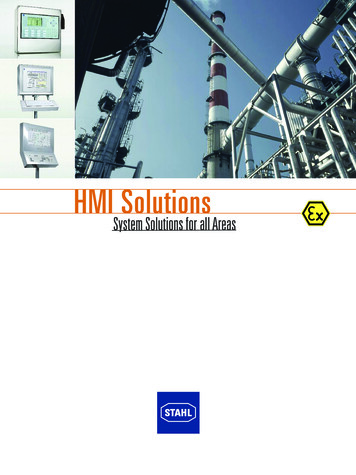
3.1 Level 1 Displays: Process OverviewLevel 1 displays contain high-level overview information that can be assimilated quickly, provide clear indication of currentperformance, and highlight anything that requires immediate attention. Control should not be performed from this display.Example Level 1 displayLevel 1 displays contain the following types of elements: High-level Key Performance Indicators (KPI) Alarms of top 2 or 3 highest priorities Important calculated parameters and conditions Important information from upstream and downstream units Advanced control mechanisms performance and status Major equipment status Appropriate trends of important parameters Indications of abnormal situations, denoting severityThere should only be one overview display for a specific operating position; however, there may be different ones fordifferent modes or process changes such as batch.Level 1 displays are crucial as they provide contextual information; however, they may not contain all information usersneed to perform their jobs. Instead, they provide current state of operations, indications of abnormal situations that may beoccurring, and quick and easy access to additional information.Level 1 displays should be designed secondarily to Level 2 displays.
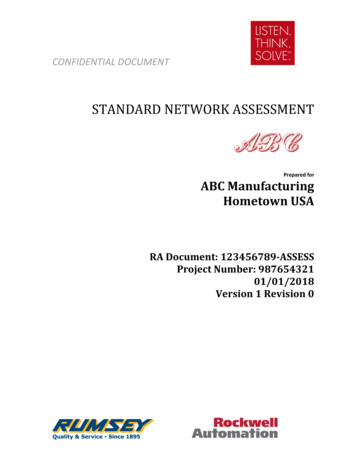
3.2 Level 2 Displays: Process Unit Operating GraphicsLevel 2 displays are the primary displays used for operators to perform their tasks and should be designed first. Level 2displays should match the users’ mental model of the machine and operation and provide easy access to related displays inthe display hierarchy. There may be multiple Level 2 displays for the same equipment to cover specific situations such asstartup, normal operation, state or product transitions, and shutdown.Example Level 2 displayLevel 2 displays contain the following types of elements that are relevant to the tasks to be accomplished by that display: Key Performance Indicators (KPI) All alarms relevant to this display (if constrained by space, then alarms of top 2 or 3 highest priorities with indicationthere are additional alarms not being displayed) Controls needed to accomplish tasks (or access to controls, such as easy access to faceplates that contain controls) Indicators needed to accomplish tasks Navigation to related displays Navigation to overview display Navigation for continuation of flow lines Indications of abnormal situations, denoting severity
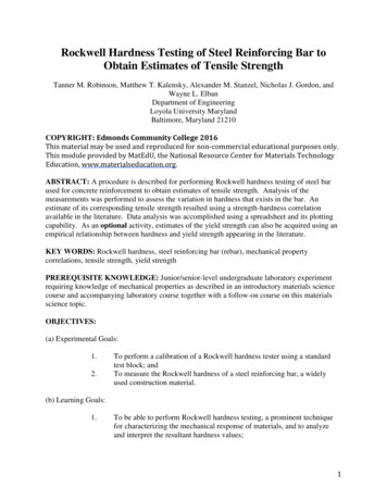
3.3 Level 3 Displays: Process Detail DisplaysLevel 3 displays contain much more detail and controls. They contain detailed view of sub-units, individual equipmentitems, components, and their related controls and indications. They are used for detailed investigations and interventionsand are intended primarily for troubleshooting or manipulating items not accessible from Level 2 displays.Example Level 3 displayLevel 3 displays contain the following types of elements that are relevant to the tasks to be accomplished by that display: Alarms of all priorities relevant to that display Controls Indicators Detail view of equipment3.4 Level 4 Displays: Process Support and Diagnostics DisplaysLevel 4 displays provide the most detail of subsystems, individual sensors, or components.Example Level 4 display
Examples include: Alarm displays with details of individual sensor status Detailed info about equipment and instrumentation Detailed status of Advanced Process Control functionality System-supplied displays such as point detail, system diagnostics, alarm summary, etc. Help displays Operating procedures Alarm documentation and response guidance4 Standard HMI TemplateRockwell Automation provides a configurable PlantPAx HMI template that can serve as a starting point for developing anew project. Templates are applied in Studio 5000 Architect and used in FactoryTalk View SE to build an HMI application.Multiple monitors are supported in the template, allowing you to implement displays on a single- or four-monitorworkstation.For more information on this template, visit publication PROCES-UM003 (PlantPAx Distributed Control System ApplicationConfiguration) or download from the Rockwell Automation Product Compatibility and Download Center (PCDC).4.1 LayoutThe single monitor HMI template configuration is below. Users view, control, and navigate from one display.The following image is of a four monitor HMI template configuration.A four monitor widescreen layout with 1920x1080 screen resolution is utilized in the standard template. Level 1, Level 2, andLevel 3 displays are provided as a part of the template along with navigation objects that promote display invocation fromone monitor to another. Alarms and trends can be filtered as a part of the display yoking when a process area is changedfrom the navigation on the Level 1 display.The HMI template requires that displays and alarms be organized using the Display Levels outlined in Section 3 of thisdocument. For each display level, the HMI template provides not only the display framework, but also global objects thatcan be used. Navigation menus and headers for both one- and four-monitor configurations are also provided.
4.1.1 HeaderHeaders contain functionality that provides access to information. The HMI template includes headers for both a singlemonitor client and a four-monitor client.Single Monitor HeaderThis header includes the following components: Display Navigation Map System Status Return to Home Screen Button Client Login/Logout Buttons Alarm and Event Banner Alarm Access Alarm SilenceFour Monitor HeaderThe four monitor header includes the same buttons as the single monitor header except for the alarm access button.Another difference is in the lack of an alarm and event banner. Instead, the alarm summary is continuously displayed onmonitor 2. Lastly, the four monitor header includes a “Refresh all Monitors” button instead of the “Return to Home Screen”button.4.1.2 Button BarsThe level 2 Button Bar is used for navigating through level 2 displays.The level 3 Button Bar is used for navigating through level 3 displays.The button bars change based on context. For example: If users change the Process Area, then Level 2 buttons will display the Level 2 displays for that Process Area If users change a Level 2 display, it wi
Automation Library of Process Objects as your HMI toolkit for implementation. An editable version of this document is available on the Rockwell Automation KnowledgeBase (answer ID 1086840). From there, the document can be downloaded and edited to incorporate specifications of your o