Transcription
User ManualOriginal InstructionsGuardmaster EtherNet/IP Network InterfaceCatalog Numbers 440R-ENETR (Series B)
Important User InformationRead this document and the documents listed in the additional resources section about installation, configuration, andoperation of this equipment before you install, configure, operate, or maintain this product. Users are required tofamiliarize themselves with installation and wiring instructions in addition to requirements of all applicable codes, laws,and standards.Activities including installation, adjustments, putting into service, use, assembly, disassembly, and maintenance arerequired to be carried out by suitably trained personnel in accordance with applicable code of practice.If this equipment is used in a manner not specified by the manufacturer, the protection provided by the equipment maybe impaired.In no event will Rockwell Automation, Inc. be responsible or liable for indirect or consequential damages resulting fromthe use or application of this equipment.The examples and diagrams in this manual are included solely for illustrative purposes. Because of the many variables andrequirements associated with any particular installation, Rockwell Automation, Inc. cannot assume responsibility orliability for actual use based on the examples and diagrams.No patent liability is assumed by Rockwell Automation, Inc. with respect to use of information, circuits, equipment, orsoftware described in this manual.Reproduction of the contents of this manual, in whole or in part, without written permission of Rockwell Automation,Inc., is prohibited.Throughout this manual, when necessary, we use notes to make you aware of safety considerations.WARNING: Identifies information about practices or circumstances that can cause an explosion in a hazardousenvironment, which may lead to personal injury or death, property damage, or economic loss.ATTENTION: Identifies information about practices or circumstances that can lead to personal injury or death, propertydamage, or economic loss. Attentions help you identify a hazard, avoid a hazard, and recognize the consequence.IMPORTANTIdentifies information that is critical for successful application and understanding of the product.Labels may also be on or inside the equipment to provide specific precautions.SHOCK HAZARD: Labels may be on or inside the equipment, for example, a drive or motor, to alert people that dangerousvoltage may be present.BURN HAZARD: Labels may be on or inside the equipment, for example, a drive or motor, to alert people that surfaces mayreach dangerous temperatures.ARC FLASH HAZARD: Labels may be on or inside the equipment, for example, a motor control center, to alert people topotential Arc Flash. Arc Flash will cause severe injury or death. Wear proper Personal Protective Equipment (PPE). Follow ALLRegulatory requirements for safe work practices and for Personal Protective Equipment (PPE).
Table of ContentsPrefaceWho Should Use this Manual . . . . . . . . . . . . . . . . . . . . . . . . . . . . . . . . . . .Summary of Changes . . . . . . . . . . . . . . . . . . . . . . . . . . . . . . . . . . . . . . . . . . .Definitions . . . . . . . . . . . . . . . . . . . . . . . . . . . . . . . . . . . . . . . . . . . . . . . . . . . .Additional Resources . . . . . . . . . . . . . . . . . . . . . . . . . . . . . . . . . . . . . . . . . . .5566Chapter 1Product OverviewAbout the Interface . . . . . . . . . . . . . . . . . . . . . . . . . . . . . . . . . . . . . . . . . . . . 7Power Up a System . . . . . . . . . . . . . . . . . . . . . . . . . . . . . . . . . . . . . . . . . 7RIUP Situations. . . . . . . . . . . . . . . . . . . . . . . . . . . . . . . . . . . . . . . . . . . . 8What the Interface Does . . . . . . . . . . . . . . . . . . . . . . . . . . . . . . . . . . . . . . . . 8Interface Features . . . . . . . . . . . . . . . . . . . . . . . . . . . . . . . . . . . . . . . . . . . . . . 9Hardware/Software Compatibility . . . . . . . . . . . . . . . . . . . . . . . . . . . . . 10Use of the Common Industrial Protocol (CIP) . . . . . . . . . . . . . . . . . . 10Understand the Producer/Consumer Model . . . . . . . . . . . . . . . . . . . . 11Specify the Requested Packet Interval (RPI) . . . . . . . . . . . . . . . . . . . . . 11Support of Data Connections . . . . . . . . . . . . . . . . . . . . . . . . . . . . . . . . . . 11Chapter 2InstallationRelay Arrangement . . . . . . . . . . . . . . . . . . . . . . . . . . . . . . . . . . . . . . . . . . . .Mount on DIN Rail . . . . . . . . . . . . . . . . . . . . . . . . . . . . . . . . . . . . . . . . . . .Removable Terminal Block . . . . . . . . . . . . . . . . . . . . . . . . . . . . . . . . . . . .Power Connections . . . . . . . . . . . . . . . . . . . . . . . . . . . . . . . . . . . . . . . . . . .Wire Size . . . . . . . . . . . . . . . . . . . . . . . . . . . . . . . . . . . . . . . . . . . . . . . . .Terminal Torque . . . . . . . . . . . . . . . . . . . . . . . . . . . . . . . . . . . . . . . . . .Network Connections . . . . . . . . . . . . . . . . . . . . . . . . . . . . . . . . . . . . . . . . .Enclosure Considerations . . . . . . . . . . . . . . . . . . . . . . . . . . . . . . . . . . . . . .Preventing Excessive Heat . . . . . . . . . . . . . . . . . . . . . . . . . . . . . . . . . . . . .131314141414151516Chapter 3Set the IP AddressOverview . . . . . . . . . . . . . . . . . . . . . . . . . . . . . . . . . . . . . . . . . . . . . . . . . . . . .Reset to Factory Default . . . . . . . . . . . . . . . . . . . . . . . . . . . . . . . . . . . . . . .Set a Private IP Address . . . . . . . . . . . . . . . . . . . . . . . . . . . . . . . . . . . . . . . .Use BootP/DHCP Server. . . . . . . . . . . . . . . . . . . . . . . . . . . . . . . . . . . . . .Use Third-party DHCP and RSLinx Software . . . . . . . . . . . . . . . . . . .1717171822Chapter 4Download and Install the Addon ProfileDownload the AOP . . . . . . . . . . . . . . . . . . . . . . . . . . . . . . . . . . . . . . . . . . . 25Install the AOP . . . . . . . . . . . . . . . . . . . . . . . . . . . . . . . . . . . . . . . . . . . . . . . 27Chapter 5Add the AOP to a Studio 5000ProjectAdd AOP . . . . . . . . . . . . . . . . . . . . . . . . . . . . . . . . . . . . . . . . . . . . . . . . . . . .Add Relays to the ENETR Interface . . . . . . . . . . . . . . . . . . . . . . . . . . . .Upload Method . . . . . . . . . . . . . . . . . . . . . . . . . . . . . . . . . . . . . . . . . . .Manual Method . . . . . . . . . . . . . . . . . . . . . . . . . . . . . . . . . . . . . . . . . . .Rockwell Automation Publication 440R-UM009C-EN-P - July 2019313333363
Table of ContentsChapter 6AOP Controller TagsGeneral Instructions for Faults . . . . . . . . . . . . . . . . . . . . . . . . . . . . . . . . .ENETR Input Tags . . . . . . . . . . . . . . . . . . . . . . . . . . . . . . . . . . . . . . . . . . .ENETR Output Tags . . . . . . . . . . . . . . . . . . . . . . . . . . . . . . . . . . . . . . . . .Dual GuardLink (DG) Tags . . . . . . . . . . . . . . . . . . . . . . . . . . . . . . . . . . .DG Fault Codes . . . . . . . . . . . . . . . . . . . . . . . . . . . . . . . . . . . . . . . . . . . . . .GuardLink Tap Tags . . . . . . . . . . . . . . . . . . . . . . . . . . . . . . . . . . . . . . . . . .GuardLink Tap Diagnostic Codes . . . . . . . . . . . . . . . . . . . . . . . . . . . . . .GuardLink Tap Fault Codes . . . . . . . . . . . . . . . . . . . . . . . . . . . . . . . . . . .DI and DIS Tags . . . . . . . . . . . . . . . . . . . . . . . . . . . . . . . . . . . . . . . . . . . . . .DI and DIS Fault Codes . . . . . . . . . . . . . . . . . . . . . . . . . . . . . . . . . . . . . . .EM Tags . . . . . . . . . . . . . . . . . . . . . . . . . . . . . . . . . . . . . . . . . . . . . . . . . . . . .EMD Tags. . . . . . . . . . . . . . . . . . . . . . . . . . . . . . . . . . . . . . . . . . . . . . . . . . . .EM and EMD Fault Codes. . . . . . . . . . . . . . . . . . . . . . . . . . . . . . . . . . . . .GLP Tags. . . . . . . . . . . . . . . . . . . . . . . . . . . . . . . . . . . . . . . . . . . . . . . . . . . . .GLP Fault Codes. . . . . . . . . . . . . . . . . . . . . . . . . . . . . . . . . . . . . . . . . . . . . .GLT Tags . . . . . . . . . . . . . . . . . . . . . . . . . . . . . . . . . . . . . . . . . . . . . . . . . . . .GLT Fault Codes . . . . . . . . . . . . . . . . . . . . . . . . . . . . . . . . . . . . . . . . . . . . .SI Tags . . . . . . . . . . . . . . . . . . . . . . . . . . . . . . . . . . . . . . . . . . . . . . . . . . . . . . .SI Fault Codes . . . . . . . . . . . . . . . . . . . . . . . . . . . . . . . . . . . . . . . . . . . . . . . .39404142434647484850515253545657586061Chapter 7Diagnostic Status IndicatorsIndicator Location . . . . . . . . . . . . . . . . . . . . . . . . . . . . . . . . . . . . . . . . . . . . 63Indicator Description. . . . . . . . . . . . . . . . . . . . . . . . . . . . . . . . . . . . . . . . . . 63Chapter 8Studio 5000 Example LogixCodeGuardLink Commands . . . . . . . . . . . . . . . . . . . . . . . . . . . . . . . . . . . . . . . .Lock and Unlock . . . . . . . . . . . . . . . . . . . . . . . . . . . . . . . . . . . . . . . . . .Lock and Unlock a Nonlocking Device. . . . . . . . . . . . . . . . . . . . . .Fault Reset Command to All GuardLink Taps . . . . . . . . . . . . . . .Guard Locking with Fault Reset Command . . . . . . . . . . . . . . . . .6565666769Chapter 9Explicit CommunicationSetup. . . . . . . . . . . . . . . . . . . . . . . . . . . . . . . . . . . . . . . . . . . . . . . . . . . . . . . . . 71Configuration Data . . . . . . . . . . . . . . . . . . . . . . . . . . . . . . . . . . . . . . . . . . . 74Appendix ASpecifications440R-ENETR Specifications. . . . . . . . . . . . . . . . . . . . . . . . . . . . . . . . . . . 77Appendix BRegulatory ApprovalsCertifications . . . . . . . . . . . . . . . . . . . . . . . . . . . . . . . . . . . . . . . . . . . . . . . . . 79Index . . . . . . . . . . . . . . . . . . . . . . . . . . . . . . . . . . . . . . . . . . . . . . . . . . . . . . . . 814Rockwell Automation Publication 440R-UM009C-EN-P - July 2019
PrefaceThis user manual is a reference guide for the 440R-ENETR Guardmaster EtherNet/IP network interface, communications interface for Guardmastersafety relays. It describes the procedures that you use to install, wire, configure,troubleshoot, and use this module.This user manual describes the following: The features of the 440R-ENETR interface. Examples of how to add the ENETR interface to an existing network. Information that can be gathered from the GSR safety relays. Information on the control signals that can be sent to the GSR relays. RSLogix examples of how to use the ENETR interface.Who Should Use thisManualUse this manual if your responsibilities include the design, installation,programming, or troubleshooting of control systems that use the 440R-ENETRGuardmaster EtherNet/IP network interface.To add a catalog number 440R-ENETR EtherNet/IP network interface to anexisting network successfully, you must be familiar with EtherNet/IP networksand the RSLinx and BootP/DHCP utilities. You must also have a basicunderstanding of electrical circuitry and familiarity with safety-related controlsystems. If you do not, obtain the proper training before using this product.Summary of ChangesThis manual contains the following new and updated information.TopicPageUpdated information for the Series B interfaceThroughoutAdded Definitions section6Updated Additional Resources table6Updated Relay Arrangement text.13Added Important table after Table 140Rockwell Automation Publication 440R-UM009C-EN-P - July 20195
PrefacePublication AG-7.1 contains a glossary of terms and abbreviations that are usedby Rockwell Automation to describe industrial automation systems. Thefollowing is a list of specific terms and abbreviations that are used in this manual.DefinitionsTerm/AbbreviationDefinitionAOP (Add-on Profile)A collection of parameters of a device that can be added to the Controller Tags of a Rockwell Automation controller in the Studio 5000 application(and earlier versions that are called the RSLogix 5000 application).Electrical MechanicalSafety Switch (EMSS)A type of tap that interfaces with safety devices that have redundant voltage-free contacts. The tap generates pulse tests to detect short circuits to theDC power supply, short circuits to the DC common, and shorts circuits between the two contacts.ENETRThe Guardmaster EtherNet/IP network interface (catalog number 440R-ENETR).GSRA Guardmaster safety relay.N.C. (Normally Closed)An electrical contact whose normal state (that is, no pressure or electrical potential applied) is in the closed position.N.O. (Normally Open)An electrical contact whose normal state (that is, no pressure or electrical potential applied) is in the open position.OLinkThe optical communication bus between GSR relays.PLCA programmable logic controller or a programmable automation controller.Reaction TimeThe time between the true states of one input to the ON state of the output.Recovery TimeThe time required for the input to be in the LO state before returning to the HI state.ResetThe GSR safety relay offers two types of reset: monitored manual and automatic/manual.Monitored ManualThe GSR safety relay performs a reset function when the reset signal goes from OFF to ON and then back to OFF in a prescribed time-period. The resetoccurs on the trailing edge.Automatic/ManualThe GSR safety relay performs a reset function if the reset input is ON. If the reset input is connected directly to 24V, the reset function is executedimmediately when the inputs become closed or active. If a contact (push button or equivalent device) is used in the reset input, the reset function isexecuted on the leading edge of the reset signal (if the inputs are closed or active).Response TimeThe time between the trigger of one input to the OFF state of the output. Throughout this manual, the safety outputs can be described as turning OFFimmediately, which means that the safety outputs turn OFF within the response time.Output Signal SwitchingDevice (OSSD)A pair of solid-state signals that are pulled up to the DC source supply. The signals are tested for short circuits to the DC power supply, short circuits tothe DC common and shorts circuits between the two signals.Single Wire Safety (SWS)A unique, safety-rated signal that is sent over one wire to indicate a safety status. The SWS can be used in safety systems that require Category 4,Performance Level e, per ISO 13849-1 and safety integrity level (SIL) 3, per IEC 62061 and IEC 61508. When an SWS signal is present, this documentdescribes this state as ACTIVE or ON. This signal is also referred to as the logic link signal.Additional ResourcesThese documents contain additional information concerning related productsfrom Rockwell Automation.ResourceDescriptionENETR Declaration of Conformity,publication SAFETY-CT004Provides declarations of conformity, certificates, andother certification details.Allen-Bradley Industrial Automation Glossary,publication AG-7.1A glossary of industrial automation terms andabbreviations.Ethernet Design Considerations,publication ENET-RM002An overview of the design considerations whendesigning an EtherNet/IP network.RSLinx Classic Getting Results Guide,publication LINX-GR001Guides you with information on how to install andnavigate the RSLinx Classic software.Industrial Automation Wiring and Grounding Guidelines,publication 1770-4.1Provides general guidelines for installing aRockwell Automation industrial system.Product Certifications website: rok.auto/certificationsProvides declarations of conformity, certificates, andother certification details.You can view or download publications ure-library/overview.page.6Rockwell Automation Publication 440R-UM009C-EN-P - July 2019
Chapter1Product OverviewAbout the InterfaceThe Guardmaster EtherNet/IP network interface is catalog number440R-ENETR (referred to as ‘ENETR interface’ throughout this manual). TheENETR interface provides connectivity to EtherNet/IP networks from theGuardmaster safety relays (GSR).This user manual describes the Series B version of the ENETR interface, whichwas released in mid-year 2018.Two significant differences between the Series A and B interface include: Webpage was discontinued to meet Internet security requirements. A faster optical bus was added to accommodate the DG relay andGuardLink designs.The ENETR interface communicates to the GSR safety relays over two opticalbuses that are on the side of the housing. EtherNet/IP connectivity is providedthrough two RJ45 connectors for 2-port pass-through support of daisy chain orring, and the existing star and tree network topologies.Figure 1 on page 9 shows the key features of the ENETR interface and thelocations of the two optical buses. Opto bus 3 communicates with the DG safetyrelay. Opto bus 2 communicates with the DI, DIS, EM, EMD, GLP, GLT, and SIsafety relays.Power Up a SystemEach time the interface is powered up, the adapter compares the number of I/Omodules present on its backplane to the chassis size value from nonvolatilememory. The adapter does not allow I/O connections until the number of I/Omodules present equals the chassis size value minus one for the adapter itself.On powerup, the interface assigns an address to every Guardmaster safety relay(up to six) in the backplane. The addressing starts from left to right with theGuardmaster safety relay to the immediate right of the interface taking the firstaddress of 1.Rockwell Automation Publication 440R-UM009C-EN-P - July 20197
Chapter 1Product OverviewRIUP SituationsYou must observe the following rules for Guardmaster safety relay systemconstruction and the removal and reinsertion of safety relays. Actual Guardmaster safety relay identification (such as, electronic keying)is done when connection establishment requests are received from thecontroller or controllers. The interface does not allow any I/Oconnections until the number and type of Guardmaster safety relays matchthe configuration in the connection request. A Guardmaster safety relay that is removed under power disruptscommunication of the other Guardmaster safety relays in the system.Connections to all safety relays are disallowed until power to the entiresystem, including the interface, is cycled to initiate readdressing the system. If safety relays of different types are removed and returned to the wronglocations, attempts to connect to these safety relays fails during verificationof the electronic ID (providing that keying has not been disabled). If safety relays of the same type are removed and returned to the wronglocations, they accept connections from the controller or controllers oncethey pass their electronic keying check.What the Interface DoesThe interface performs the following primary tasks: Real-time input data (also known as implicit messaging) - the interfaceserves as a bridge between Guardmaster safety relays and the networkL7XENBTEtherNet/IP NetworkE GuardmasterNSafetyETRelaysREN ControlLogixB I/OTOtherNetworkDevices Support of messaging data for programming information (also known asExplicit Messaging)8Rockwell Automation Publication 440R-UM009C-EN-P - July 2019
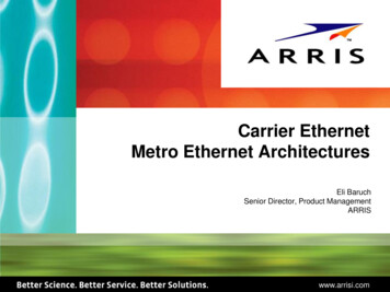
Product OverviewInterface FeaturesChapter 1Features of the interface include: Use of EtherNet/IP messages encapsulated within standard TCP/UDP/IP protocol Common application layer with ControlNet and DeviceNet networks Interfacing via Category 5 rated twisted-pair cable Half/full duplex 10 Mbit or 100 Mbit operation DIN Rail mounting for 440R-ENETR interface Communication from Guardmaster safety relays on the same DIN rail(mounted immediately to the right of the interface) as the ENETRinterface to controllers on the EtherNet/IP networkIMPORTANT Each safety relay must be mounted to the right of the interface within5 mm [0.2 in.] of the next safety relay.Communication supported by RSLinx softwareIP address that is assigned via standard BOOTP or DHCP toolsConfiguration via RSLogix 5000 softwareNo network scheduling requiredNo routing tables requiredSupport of connections from multiple controllers simultaneouslyYou must use RSLogix 5000 software to configure these features. For moredetails on configuration, see Overview on page 17.Figure 1 - Key Features of the 440R-ENETR Interface45231678ItemDescriptionItemDescription135 mm (1.38 in.) DIN rail mounting5Status Indicators2Optical communications bus (OLink) 2.06EtherNet/IP address rotary switches3Optical communications bus (OLink) 3.07Two Ethernet network RJ45 connectors4Removable terminal block822.5 mm (0.89 in.) wide housingRockwell Automation Publication 440R-UM009C-EN-P - July 20199
Chapter 1Product OverviewHardware/SoftwareCompatibilityThe interface and the applications that are described in this manual arecompatible with the following firmware revisions and software releases.Contact your Rockwell Automation sales office or Allen-Bradley distributor ifyou need software or firmware updates to use this equipment.Use of the CommonIndustrial Protocol (CIP)ProductFirmware Revision/ Software Release440R-ENETR interface1.xx or later1756-ENBT2.3 or laterLogix controller19 or laterRSLogix 5000 software19 or laterRSLinx software2.52 or laterGSR DI (Catalog number 440R-D22R2)2 or laterGSR DIS (Catalog number 440R-D22S2)2 or laterGSR EM (Catalog number 440R-EM4R3)2 or laterGSR EMD (Catalog number 440R-EM4R2D)2 or laterGSR GLP (Catalog number 440R-GL2S1P)2 or laterGSR GLT (Catalog number 440R-GL2S2T)2 or laterThe adapter uses the Common Industrial Protocol (CIP). CIP is the applicationlayer protocol that is specified for EtherNet/IP, the Ethernet Industrial Protocol,and for ControlNet and DeviceNet networks. It is a message-based protocol thatimplements a relative path to send a message from the producing device in asystem to the consuming devices.The producing device contains the path information that steers the messagealong the proper route to reach its consumers. Since the producing device holdsthis information, other devices along the path simply pass this information; theydo not store it.This configuration has the following significant benefits: You do not need to configure routing tables in the bridging modules,which greatly simplify maintenance and module replacement. You maintain full control over the route that each message takes, whichenables you to select alternative paths for the same end device.10Rockwell Automation Publication 440R-UM009C-EN-P - July 2019
Product OverviewUnderstand the Producer/Consumer ModelChapter 1The CIP producer and consumer networking model replaces the old source anddestination (master and slave) model. The producer and consumer model reducesnetwork traffic and increases speed of transmission. In traditional I/O systems,controllers poll input modules to obtain their input status. In the CIP system, acontroller does not poll input modules. Instead, they produce (multicast orunicast) their data either upon a change of state (COS) or periodically.Multicast is the default mode for version 17 Logix and earlier controllers andunicast is the default for version 18 with multicast as a selectable option.The frequency of update depends upon the options that are chosen duringconfiguration and where on the network the input module resides. The inputmodule, therefore, is a producer of input data, and the controller is a consumer ofthe data.The controller also produces data for other controllers to consume. Theproduced and consumed data is accessible by multiple controllers and otherdevices over the EtherNet/IP network. This data exchange conforms to theproducer and consumer model.Specify the RequestedPacket Interval (RPI)The Requested Packet Interval or RPI is the update rate that is specified for aparticular piece of data on the network. The RPI can be specified for theinterface and includes all Guardmaster safety relays in the system.When you add an interface to the I/O configuration of a controller, you mustenter the RPI as a parameter. This value specifies how often to produce the datafor that device. For example, if you specify an RPI of 50 ms, it means that every50 ms the device should send its data to the controller and the controller shouldsend the consumed (output) data to the device.Use RPIs only for devices that exchange data. For example, a ControlLogix EtherNet/IP bridge in the same chassis as the controller does not require an RPI,because it is not a data-producing member of the system. Its use is only as a bridgeto remote racks.Support of DataConnectionsTheGuardmaster EtherNet/IP Network Interface supports data connections.A data connection to the interface is a grouping of data from one or moreGuardmaster safety relays into one block of data that is sent over one connectionat the same data rate.See the EtherNet/IP Design Considerations Reference Manual,publicationENET-RM002 for more information on connections.Rockwell Automation Publication 440R-UM009C-EN-P - July 201911
Chapter 1Product OverviewNotes:12Rockwell Automation Publication 440R-UM009C-EN-P - July 2019
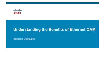
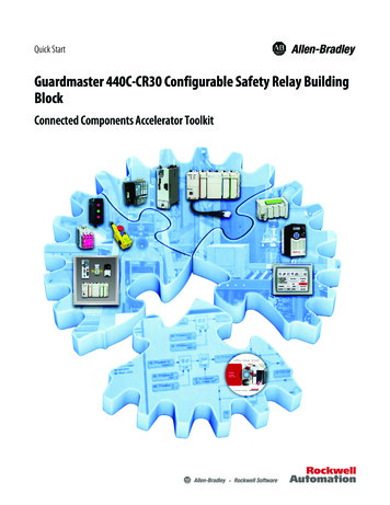
Chapter2InstallationRelay ArrangementFigure 2 shows a typical setup. The ENETR interface must be at the leftmostposition. Up to a maximum of six GSR safety relays can be mounted to the rightof the ENETR interface. When OLink 3.x devices (for example, GuardmasterDG safety relays) are used, they must be located next to the ENETR interface.The other OLink 2.0 relays can be mounted in any order. The DG safety relay hasboth OLink 2.0 and 3.x, so it can pass information from OLink 2.0 devices to theENETR interface.Figure 2 - Typical Arrangement of ENETR Interface and GSR RelaysA1 A2LINK1ENETRIP: 192. 168. 1. ABCMSLNK1LNK2NSABCS12 S22 S32 S42 S12 S22 S32 S42A1 A2 S11 S21 A1 A2 S11 S21PWR/FaultOUTIN 1IN 2OUT XIN XResetFBPWR/FaultOUTIN 1IN 2OUT XIN XResetFBConfig/SetConfig/SetDGResetSel./Save9 0 1 Time8276 5 43DGS12 S22 S32 S42 S12 S22 S32 S42A1 A2 S11 S12 A1 A2 S11 S12PWR/FaultPWR/FaultIN1IN1IN2IN2Logic INLogic INOUTOUT00LOGICLOGIC11876 5423876 542333 34 43 44A1 A2 S11 S12PWR/FaultLogic INOUT33 34 43 44A1ResetX1 X2 X3 X4 X1 X2 X3 X413 14 23 24 13 14 23 2413 14 23 24DI34 44 14 24DISL12 L11 Y32 S34 L12 L11 Y32 S3413 14 23 24 34 44 14 24Logic INOUTRANGE 0 1237 6 541231049587 698TIMESel./Save9 0 1 Time8276 5 4337 38 47 48A1 A2 B1 B2PWR/FaultB113 14 23 24EMEMDL12 L11 X3213 14 23 24L12 L11 X3217 18 27 28LINK2Locate DG safety relays closestto the ENETR interfaceMount on DIN RailMax separation betweenrelays is 5 mm (0.2 in.).Follow these steps to mount the ENETR interface on a DIN rail.1. Position the adapter vertically above an IEC standard (35x7.5x1 mm[1.38x0.3x0.04 in.]) DIN rail at a slight angle (DIN rail catalog number199-DR1; 46277-3).DIN RailDIN Rail Latch2. Press down firmly to install the interface on the DIN rail.To remove your interface from the DIN rail, pry the DIN rail latch downwardsuntil there is separation from the latch and the DIN rail.Rockwell Automation Publication 440R-UM009C-EN-P - July 201913
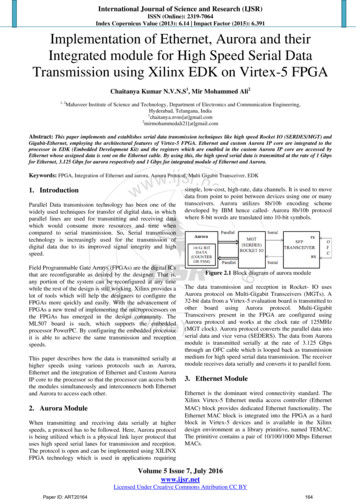
Chapter 2InstallationRemovable Terminal BlockThe ENETR interface has one removable terminal block. Use a screwdriver (oryour thumb) as a lever to remove the blocks. As shown in Figure 3, insert thescrewdriver into the slot and pry up.Figure 3 - Terminal Block RemovalPower ConnectionsThe ENETR interface requires only a 24V DC connection and common.Connect 24V DC to terminal A1 and the 24V common to terminal A2 as shownin Figure 4.The 24V supply must provide power to the ENETR interface and the GSR relaysthat it is monitoring. If a power cycle is required to clear a fault on a GSR relay,then power also has to be cycled to the ENETR interface to re-establish theoptical link communications. Having one power supply eliminates the need fortwo power cycles to clear a fault and re-establish the optical communications.Figure 4 - Power ConnectionsA1 24V DC SupplyEthernet A2 24V CommonRJ45connectorTOP VIEWWire SizeEach terminal accommodates copper wire with size from 0.14 2.5 mm2(26 14 AWG). Use copper wire that withstands 60 75 C (140 167 F).Each terminal can accommodate up to two wires.Terminal TorqueTorque terminals to 0.4 N m (4 lb in).14Rockwell Automation Publication 440R-UM009C-EN-P - July 2019
InstallationNetwork ConnectionsChapter 2The ENETR interface has two network connections, using standard RJ45connectors. The connection that is labeled LNK1 is on the top of the housing,and the LNK2 connection is on the bottom of the housing. Connection can bemade to either LNK1 or LNK2. The network connection is a repeater; the signalcoming into one Link is repeated at the other Link. Figure 5 shows an example ofa system with both LNK1 and LNK2 connections.Figure 5 - Example Showing Link 1 and Link 2 Network ConnectionsEnclosure ConsiderationsMost applications require installation in an industrial enclosure to reduce theeffects of electrical interference and environmental exposure. Pollution Degree 2is an environment where normally only non-conductive pollution occurs exceptthat occasionally temporary conductivity that is caused by condensation can beexpected. Overvoltage Category II is the load level section of the electricaldistribution system. At this level, transient voltages are controlled and do notexceed the impulse voltage capability of the product insulation.This equipment is intended for use in a Pollution Degree 2 industrialenvironment, in overvoltage Category II applications (as defined inIEC 60664-1), at altitudes up to 2000 m (6562 ft) without derating. Thisequipment is considered Group 1, Class A industrial equipment according toIEC/CISPR 11. Without appropriate precautions, there can be difficulties withelectromagnetic compatibility in residential and other environments due toconducted and radiated disturbances.This equipment is supplied as ope
6 Rockwell Automation Publication 440R-UM009C-EN-P - July 2019 Preface Definitions Publication AG-7.1 contains a glossary of terms and abbreviations that are used by Rockwell Automation to describe industrial automation systems. The following is a list of specific terms and abbreviations that are used in this manual.