Transcription
PD T8110B/T8110TrustedTrusted TMR ProcessorProduct OverviewThe Trusted Processor is the main processing component in a Trusted System. It is a powerful,user-configurable module providing overall system control and monitoring facilities and processesinput and output data received from a variety of analogue and digital Input / Output (I/O) modulesacross a Trusted TMR Inter-Module Communications Bus.The range of applications for the Trusted TMR Processor vary in integrity level and include fire andgas control, emergency shutdown, monitoring and control, and turbine control.Features: Triple Modular Redundant (TMR), fault tolerant (3-2-0) operation. Hardware Implemented Fault Tolerant (HIFT) architecture. Dedicated hardware and software test regimes which provide very fast fault recognition andresponse times. Automatic fault handling without nuisance alarming. Time-stamped fault historian. Hot replacement (no need to re-load programs). Full suite of IEC 61131-3 programming languages. Front panel indicators that show module health and status. Front panel RS232 serial diagnostics port for system monitoring, configuration andprogramming. IRIG-B002 and 122 time synchronisation signals (available on T8110B only). Active and Standby processor fault and failure contacts. Two RS422 / 485 configurable 2 or 4 wire connections (available on T8110B only). One RS485 2 wire connection (available on T8110B only). TϋV Certified IEC 61508 SIL 3.Rockwell Automation Publication PD T8110B/T8110Issue 22
TrustedPD T8110B/T8110Page intentionally left blankRockwell Automation Publication PD T8110B/T8110Issue 22
Trusted TMR ProcessorPREFACEPREFACEIn no event will Rockwell Automation be responsible or liable for indirect or consequential damagesresulting from the use or application of this equipment. The examples given in this manual areincluded solely for illustrative purposes. Because of the many variables and requirements related toany particular installation, Rockwell Automation does not assume responsibility or reliability foractual use based on the examples and diagrams.No patent liability is assumed by Rockwell Automation, with respect to use of information, circuits,equipment, or software described in this manual.All trademarks are acknowledged.DISCLAIMERIt is not intended that the information in this publication covers every possible detail about theconstruction, operation, or maintenance of a control system installation. You should also refer toyour own local (or supplied) system safety manual, installation and operator/maintenance manuals.REVISION AND UPDATING POLICYThis document is based on information available at the time of its publication. The documentcontents are subject to change from time to time. The latest versions of the manuals are available atthe Rockwell Automation Literature Library under "Product Information" information "CriticalProcess Control & Safety Systems".TRUSTED RELEASEThis technical manual applies to Trusted Release: 3.6.1.LATEST PRODUCT INFORMATIONFor the latest information about this product review the Product Notifications and Technical Notesissued by technical support. Product Notifications and product support are available at the RockwellAutomation Support Centre athttp://rockwellautomation.custhelp.comAt the Search Knowledgebase tab select the option "By Product" then scroll down and select theTrusted product.Some of the Answer ID’s in the Knowledge Base require a TechConnect Support Contract. For moreinformation about TechConnect Support Contract Access Level and Features please click on thefollowing nswers/detail/a id/50871This will get you to the login page where you must enter your login details.IMPORTANTA login is required to access the link. If you do not have an account then you can create oneusing the "Sign Up" link at the top right of the web page.Rockwell Automation Publication PD T8110B/T8110Issue 22i
PREFACETrusted TMR ProcessorDOCUMENTATION FEEDBACKYour comments help us to write better user documentation. If you discover an error, or have asuggestion on how to make this publication better, send your comment to our technical supportgroup at http://rockwellautomation.custhelp.comiiIssue 22Rockwell Automation Publication PD T8110B/T8110
Trusted TMR ProcessorPREFACESCOPEThis manual specifies the maintenance requirements and describes the procedures to assisttroubleshooting and maintenance of a Trusted system.WHO SHOULD USE THIS MANUALThis manual is for plant maintenance personnel who are experienced in the operation andmaintenance of electronic equipment and are trained to work with safety systems.SYMBOLSIn this manual we will use these notices to tell you about safety considerations.SHOCK HAZARD: Identifies an electrical shock hazard. If a warning label is fitted, itcan be on or inside the equipment.WARNING: Identifies information about practices or circumstances that can causean explosion in a hazardous environment, which can cause injury or death,property damage or economic loss.ATTENTION: Identifies information about practices or circumstances that can causeinjury or death.CAUTION: Identifies information about practices or circumstances that can causeproperty damage or economic loss.BURN HAZARD: Identifies where a surface can reach dangerous temperatures. If awarning label is fitted, it can be on or inside the equipment.This symbol identifies items which must be thought about and put in place whendesigning and assembling a Trusted controller for use in a Safety InstrumentedFunction (SIF). It appears extensively in the Trusted Safety Manual.IMPORTANTIdentifies information that is critical for successful application and understanding ofthe product.NOTEProvides key information about the product or service.TIPTips give helpful information about using or setting up the equipment.Rockwell Automation Publication PD T8110B/T8110Issue 22iii
PREFACETrusted TMR ProcessorWARNINGS AND CAUTIONSWARNING: EXPLOSION RISKDo not connect or disconnect equipment while the circuit is live or unless the area isknown to be free of ignitable concentrations or equivalentAVERTISSEMENT - RISQUE D’EXPLOSIONNe pas connecter ou déconnecter l’équipement alors qu’il est sous tension, sauf sil’environnement est exempt de concentrations inflammables ou équivalenteMAINTENANCEMaintenance must be carried out only by qualified personnel. Failure to follow theseinstructions may result in personal injury.CAUTION: RADIO FREQUENCY INTERFERENCEMost electronic equipment is influenced by Radio Frequency Interference. Cautionshould be exercised with regard to the use of portable communications equipmentaround such equipment. Signs should be posted in the vicinity of the equipmentcautioning against the use of portable communications equipment.CAUTION:The module PCBs contains static sensitive components. Static handling precautionsmust be observed. DO NOT touch exposed connector pins or attempt to dismantle amodule.ivIssue 22Rockwell Automation Publication PD T8110B/T8110
Trusted TMR ProcessorPREFACEISSUE RECORDIssueDateComments11Oct 05Format12Aug 06Corrections13Sep 063.5 Scan Time Calc14Nov 06Specifications15Dec 06I/O Definition16Mar 07Hot Swap17Sep 07Max Scan Time18Feb 08TTMRP 0 scaling19Sep 14Fault/Fail Relay information added. Note added to OEM parametersRack 1.20Sep 15Rebranded and reformatted21Apr 16Updated to incorporate IEEE standards with correction of typographicalerrors.22Jun 16Standardise the Relative Humidity and Operating TemperaturespecificationsRockwell Automation Publication PD T8110B/T8110Issue 22v
PREFACETrusted TMR ProcessorPage intentionally left blankviIssue 22Rockwell Automation Publication PD T8110B/T8110
Trusted TMR ProcessorTable of ContentsTable of Contents1.Description . 31.1.1.2.1.3.1.4.Overview . 3Hardware Implemented Fault Tolerant (HIFT) Clock . 5Power Distribution . 5Fault/Fail Relays . 52.Installation . 72.1.2.2.2.3.3.Module Insertion/Removal . 7PCBs and Connectors . 7Module Pinout Connections. 82.3.1. External I/O Connector (PL1). 8Application . 113.1.Module Configuration . 113.1.1. Updater Section. 113.1.2. Security Section . 113.1.3. ICS2000 Section . 113.1.4. System Section . 123.1.5. ISaGraf Configuration Section . 153.1.6. Chassis Section . 163.1.7. InterRange Instrumentation Group (IRIG). 163.1.8. Additional User Serial Ports. 173.2.Complex I/O Equipment Definition . 183.2.1. I/O Complex Equipment ‘TTMRP’. 183.3.Inter-Module Bus . 223.3.1. Processor Memory Voting Bus . 223.3.2. Inter-Module Bus Voting Bus . 223.3.3. Processor Voting Bus . 223.3.4. Front Panel Voting Bus . 223.4.Isolation . 244.4.1.4.2.4.3.4.4.4.5.4.6.4.7.Operation . 25System Overheads. 26Online Operator Inputs . 26Standby Processor . 26Module Management . 27Security. 27Front Panel . 28Module Status LEDs. 284.7.1. Reset Button . 30Rockwell Automation Publication PD T8110B/T8110Issue 221
Table of ContentsTrusted TMR Processor4.7.2. Maintenance Enable Keyswitch . 30Composite Scan Time Estimation (pre TÜV release 3.5). 304.8.1. Central Modules . 314.8.2. Input Modules . 314.8.3. Output Modules . 324.8.4. Application Execution . 324.8.5. Composite Scan Time . 334.8.6. Example Calculation . 334.9.Composite Scan Time Estimation (from TÜV release 3.5) . 354.9.1. Input Modules . 354.9.2. Output Modules . 354.9.3. Application Execution . 364.9.4. Communications. 364.9.5. Example Calculation . 374.8.5.Fault Finding and Maintenance. 395.1.5.2.5.3.Testing and Diagnostics. 39Faults . 39Transfer between Active and Standby Processor Modules . 406.Specifications. 432Issue 22Rockwell Automation Publication PD T8110B/T8110
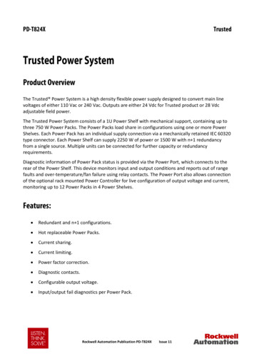
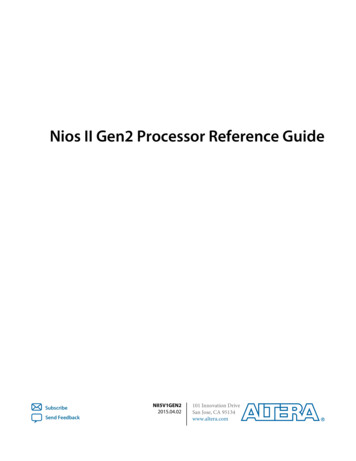
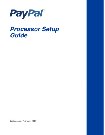
Trusted TMR Processor1. Description1. DescriptionFigure 1 Module Architecture1.1. OverviewThe Trusted TMR Processor is a fault tolerant design based on a Triple Modular Redundant(TMR) architecture operating in a lock-step configuration. Figure 1 shows, in simplifiedterms, the basic structure of the Trusted TMR Processor module.The module contains three Processor fault containment regions (FCR), each containing aMotorola Power PC series Processor and its associated memory (EPROM, DRAM, Flash ROM,and NVRAM), memory mapped I/O, voter and glue logic circuits. Each Processor FCR hasvoted two-out-of-three (2oo3) read access to the other two Processor’s FCR memorysystems to eliminate divergent operation.The module’s three Processors store and execute the application program, scan and updatethe I/O modules and detect system faults. Each Processor executes the application programindependently, but in lock-step synchronisation with the other two. Should one of theProcessors diverge, additional mechanisms allow the failed Processor to re-synchronise withthe other two.Each Processor has an interface which consists of an input voter, discrepancy detector logic,memory, and an output driver bus interface to the Inter-Module Bus. The output of eachProcessor is connected by the module connector to a different channel of the triplicatedInter-Module Bus.Rockwell Automation Publication PD T8110B/T8110Issue 223
1. DescriptionTrusted TMR ProcessorCommunication between the Trusted TMR Processor and modules in other chassis is viaeither a Trusted Interface module, such as the Trusted TMR Interface to a Regent Plus I/Ochassis, or an Expander Interface to an Expander chassis.The functions of the four types of module memory are: EPROM - Holds module bootstrap loader Flash ROM - Stores module firmware and the application program DRAM - Working memory with scaleable capacity NVRAM - Holds data such as event logs and retained program dataNote: The NVRAM provides data retention for up to 10 years.The Front Panel comprises a fault containment region (FCR D) separate from the other FCRsand contains non-critical functions. These include: The diagnostics port and maintenance enable keyswitch mounted on the front panelof the Processor. The serial communications drivers and the IRIG-B interface. These are accessedthrough the I/O connector via adapter units at the rear of the Processor. Participates in all module voting operations. Sends Fault/Fail signals to external indicators via the adapter units at the rear of theProcessor.Two IRIG-B input standards are available to the Processor; IRIG-B002 and IRIG-B122. Thestandard used by the Processor is controlled by software setting a flag in the memory. TheIRIG-B signals are used to synchronise systems and time-stamp entries in the Sequence ofEvents (SOE) log.Three serial communication options are available from the 4-channel UniversalAsynchronous Receiver/Transmitter (UART). These are detailed as follows: Channel 0Front Panel Diagnostic Port (RS232) Channel 1Not configured Channel 2Communications Serial Port 2 (RS422/485) Channel 3Communications Serial Port 3 (RS422/485)The Trusted operating system (Trusted OS) is used in support of the Motorola Power PCseries processor architecture. The real time kernel is a high speed, high functionality kernelmade for fault tolerant distributed systems. The distributed communication is madetransparent over all processors.The kernel provides basic services (such as basic memory management), and interferencefree software environments which allow software of various integrity levels to reside andco-operate in a single processing environment.4Issue 22Rockwell Automation Publication PD T8110B/T8110
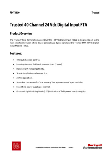
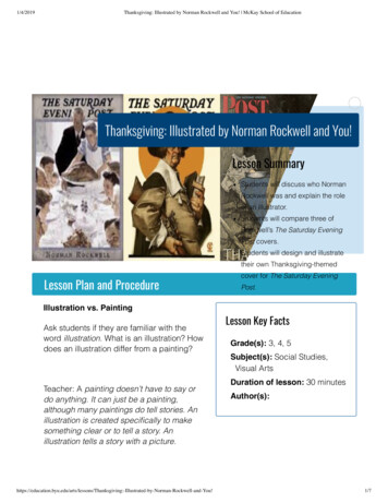
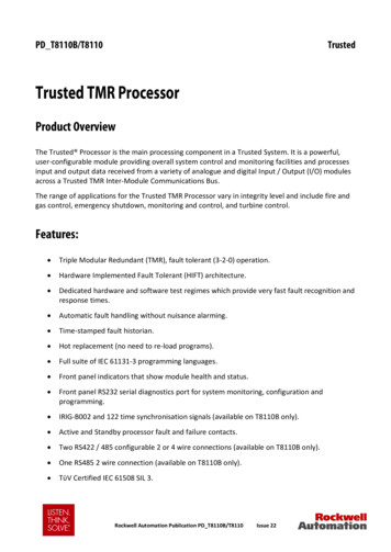
Trusted TMR Processor1. DescriptionAn Application Program Interface (API) provides a consistent run-time interface for theservices provided by the Trusted TMR Processor to the application program. The API alsoperforms the same function to system-specific software executing within the Trusted TMRProcessor.1.2. Hardware Implemented Fault Tolerant (HIFT) ClockEach of the Processor and Front Panel FCR regions has its own HIFT clock, which areprovided with a synchronisation reference signal from the fault tolerant reference clocks.1.3. Power DistributionEach of the Processor and FCRs derive their internal voltages from dual redundant 24 Vdcpower supplied via the module connector from the Trusted Controller chassis backplane.1.4. Fault/Fail RelaysEach Processor generates a Fault and Fail signal from two relays located in the Front PanelIRIG containment region.Figure 2 Fault/Fail RelaysThe Fault and Fail signals are initiated by the Front Panel Light Emitting Diode (LED)containment region. A Fault signal is generated when a system fault occurs. The SystemHealthy LED flashes Red and the Fault signal drives the relay RL1 NC contacts open.Rockwell Automation Publication PD T8110B/T8110Issue 225
1. DescriptionTrusted TMR ProcessorThe Fail relay stays healthy if one of two Processors goes faulty and loses one slice but theother Processor takes over and goes active. If neither Processor is active with two workingslices a Fail signal is generated indicating that the system has shut down. The Fail signaldrives relay RL2 NC contacts open.The Fail and Fault relay NC contact signals are routed through SK1 to the TMR ProcessorInterface Adapter to connectors J2 and J3.6Issue 22Rockwell Automation Publication PD T8110B/T8110
Trusted TMR Processor2. Installation2. Installation2.1. Module Insertion/RemovalCAUTION:The module contains static sensitive parts. Static handling precautions must beobserved. Specifically ensure that exposed connector pins are not touched. Under nocircumstances should the module housing be removed.Before installation, visually inspect the module for damage. Ensure that the module housingappears undamaged and inspect the I/O connector at the back of the module for bent pins.If the module appears damaged or any pins are bent, do not install the module. Do not tryto straighten bent pins. Return the module for replacement.Ensure that the module is of the correct type.Record the module type, revision and serial number before installation.To install the module:1. Ensure that the field cable assembly is installed and correctly located.2. Release the ejector tabs on the module using the release key. Ensure that the ejectortabs are fully open.3. Holding the ejectors, carefully insert the module into the intended slot.4. As soon as the Front Panel LEDs illuminate, push the module fully home by pressingon the top and bottom of the module fascia. The module should be insertedpromptly to ensure that it connects to the Interface Adapter before reading thelicenses.5. Close the module ejectors, ensuring that they click into their locked position.The module should mount into the chassis with a minimum of resistance. If the module doesnot mount easily, do not force it. Remove the module and check it for bent or damagedpins. If the pins have not been damaged, try reinstalling the module.2.2. PCBs and ConnectorsThe Trusted TMR Processor comprises five separate Printed Circuit Board (PCB) assemblies:1. Three identical Processor boards.2. One Riser board to provide the connections between the PCB assemblies.3. One module Main board that provides the inter-module bus connection and FrontPanel facilities.Rockwell Automation Publication PD T8110B/T8110Issue 227
2. InstallationTrusted TMR Processor2.3. Module Pinout Connections2.3.1.External I/O Connector (PL1)This connector provides a number of discrete input and outputs. These are provided toallow the Trusted TMR Processor status to be monitored by external hardware, and to allowthe Trusted TMR Processor to monitor the power supply status signals. The connector alsoprovides access to the communications ports and connections for IRIG-B input signals. Toenable the communications ports and IRIG-B facilities to be accessed, the user must installthe following: Processor Interface Adapter T8120 for the communications ports. Processor Interface Adapter Unit (IRIG-B) T8121 for both communications ports andIRIG-B facilities.Note: IRIG-B and serial facilities are only available on the T8110BPL1 is a 48-way DIN41612 E type connector.RowPin8ACE2Fault relay (NC)DIAG RTNFailed relay (NC)4Fault relay (common)DIAG IN 1Failed relay (common)6Fault relay (NO)0 V Port 1Failed relay (NO)8Not ConnectedSerial Port 1 BNot Connected105V DSerial Port 1 AIRIG-B122 12DATA OUT0V Port 2IRIG-B122-14ENABLESerial Port 2 B TXReserved16DATA INSerial Port 2 A TXReserved18CLKSerial Port 2 B RX/TXIRIG-B002-200VSerial Port 2 A RX/TXIRIG-B002 22Chassis GND0 V Port 3Chassis GND24Chassis GNDSerial Port 3 B TXChassis GND26Chassis GNDSerial Port 3 A TXChassis GNDIssue 22Rockwell Automation Publication PD T8110B/T8110
Trusted TMR Processor2. InstallationRowPinACE2824 V PSU 1 LV WarningSerial Port 3 B RX/TX24V PSU 1 FailShutdown3024 V PSU 2 LV WarningSerial Port 3 A RX/TX24V PSU 2 FailShutdown3224 V Return24 V Return24V ReturnTable 1 External I/O Connector Pin-outRockwell Automation Publication PD T8110B/T8110Issue 229
2. InstallationTrusted TMR ProcessorPage intentionally left blank10Issue 22Rockwell Automation Publication PD T8110B/T8110
Trusted TMR Processor3. Application3. Application3.1. Module ConfigurationThe Trusted TMR Processor requires no hardware configuration.Every Trusted System requires a System.INI configuration file. Details of how to design thisare given in PD-T8082 (Trusted Toolset Suite). The configuration has a Processor assigned tothe left slot of the Processor chassis by default. The System Configurator allows theselection of options on ports, IRIG and system functions. The use of the System Configuratoris described in PD-T8082. The options are described below.3.1.1.Updater SectionIf Auto Protect Network Variables is selected, this configures the Trusted System to use areduced Modbus Protocol map. See product description PD-8151B (Trusted CommunicationInterface Module) for further details.Inter Group Delay equates to the Modbus update cycle. This is the minimum periodbetween successive Modbus update messages sent to each of the CommunicationsInterface Modules. The default value (as shown) is 50 ms which provides a compromisebetween latency and performance. Adjustment is made in 32 integer ms increments, i.e. avalue of 33 will equal 64 ms as will 64.This may be increased or decreased as required,however since only one update message is sent per application scan, and an applicationscan may often be more than 50 ms, there is little benefit in adjusting this variable.3.1.2.Security SectionThe above display is also used to configure a password allowing the user to interrogate aTrusted System using the Windows-based HyperTerminal facility or a similar terminalprogram. The password is configured by selecting the New Password button and enteringthe new password twice in the displayed dialogue box.3.1.3.ICS2000 SectionThis section only applies to Trusted Systems connected via a Trusted to ICS2000 InterfaceAdapter to an ICS2000 system. This allows the data sources for the three mimic tables to beselected. Please refer to your Trusted supplier for further information.Rockwell Automation Publication PD T8110B/T8110Issue 2211
3. Application3.1.4.Trusted TMR ProcessorSystem SectionWARNING:Changes made to the System section may affect System performance, Fault Detectiontimes and violate the process safety tolerances.Entries to this section are typed directly into the SYSTEM Section text window.DEFINITIONS NIO Module - Native Input or Output (I/O) Module. This refers to all I/O modulesresident in a Trusted Chassis. It does not refer to I/O modules resident in otherchassis types and communicating via a bridge interface module. Dual I/O - Module using two voted circuits to connect to a field device. TMR I/O - Module using three voted circuits to connect to a field device.rim intervalThe value is specified in milliseconds. It specifies the minimum amount of time that mustelapse between polls of Trusted TMR Interface Modules.Changes to this value are reflected by the system immediately after the System.INI file isloaded.Format: rim interval xx Default is 0.pim intervalThe value is specified in milliseconds. It specifies the minimum amount of time that mustelapse between polls of the Trusted Communication Interface Modules.Changes to this value are reflected by the system immediately after the System.INI file isloaded.Format: pim interval xx Default is 0.discrepancy valThe value is specified in milliseconds. It specifies the time that a TMR input or outputchannel must be discrepant before the TMR Processor reports the Channel Discrepancyfault.The value applied here will affect all TMR NIO Modules (not Dual NIO Modules).12Issue 22Rockwell Automation Publication PD T8110B/T8110
Trusted TMR Processor3. ApplicationChanges to this value are not implemented until the TMR Processor is rebooted after thedownload of the System.INI file.Format: discrepancy val xx Default is 2000.dual discrepancy valThe value is specified in milliseconds. It specifies the time that a Dual input or outputchannel must be discrepant before the TMR Processor reports the Channel Discrepancyfault.The value applied here will affect all Dual NIO Modules.Changes to this value are not implemented until the TMR Processor is rebooted after thedownload of the System.INI file.Format: dual discrepancy val xx Default is 2000.ana discrep valThe value is specified as 512 counts per volt. It specifies the allowed difference betweenvoltage readings of Analogue Input channel slices before the TMR Processor indicates aChannel Discrepancy.The value applied here affects all Analogue Input Modules (Dual and TMR).Changes to this value are not implemented until the TMR Processor is rebooted after thedownload of the System.INI file.Format: ana discrep val xx Default 40 (40/512 volts or 78 mV).dig discrep valThe value is specified as 512 counts per volt for T8402 and T8403 and 128 counts per voltfor T8423. It specifies the allowed difference between voltage readings of T8402, T8403 andT8423 Digital Input channel slices before the TMR Processor indicates a ChannelDiscrepancy.Changes to this value are not implemented until the TMR Processor is rebooted after thedownload of the System.INI file.Rockwell Automation Publication PD T8110B/T8110Issue 2213
3. ApplicationTrusted TMR ProcessorFormat: dig discrep val xx Default 250 (e.g. 250/512 volts or 512 mV for T84
The Trusted Processor is the main processing component in a Trusted System. It is a powerful, user-configurable module providing overall system control and monitoring facilities and processes input and output data received from a variety of analogue and digital Input / Output (I/O) modules across a Trusted TMR Inter-Module Communications Bus.