Transcription
PD T8153TrustedTrusted Communication Interface AdapterProduct OverviewThis document provides general information for the Trusted Communication Interface AdapterT8153. The Assembly provides easy access to the communications ports of the TrustedCommunication Interface Modules in the Controller Chassis for Peer to Peer communications, DCSand other links, networked PCs etc., and external connections.Note: Gateway module Ethernet ports do not work well with a T8153 Communications Interface Adapter. It is possibleto get most ports working by forcing the arbitration to 100BaseT and full duplex, however, the T8173 Gateway Adapteris recommended instead for use with the Gateway Module and also includes connections for a keyboard, video andmouse ports.Features: Allows easy access for external systems to communicate with a Trusted System. Easy installation i.e. connects directly to the back of the Trusted Communication Interface. Two 10/100BaseT connections. Four RS422/485 connections. Two RS232 connections (one ‘full’ RS232).Rockwell Automation Publication PD T8153Issue 14
TrustedPD T8153Page intentionally left blankRockwell Automation Publication PD T8153Issue 14
Trusted Communication Interface AdapterPREFACEPREFACEIn no event will Rockwell Automation be responsible or liable for indirect or consequential damagesresulting from the use or application of this equipment. The examples given in this manual areincluded solely for illustrative purposes. Because of the many variables and requirements related toany particular installation, Rockwell Automation does not assume responsibility or reliability foractual use based on the examples and diagrams.No patent liability is assumed by Rockwell Automation, with respect to use of information, circuits,equipment, or software described in this manual.All trademarks are acknowledged.DISCLAIMERIt is not intended that the information in this publication covers every possible detail about theconstruction, operation, or maintenance of a control system installation. You should also refer toyour own local (or supplied) system safety manual, installation and operator/maintenance manuals.REVISION AND UPDATING POLICYThis document is based on information available at the time of its publication. The documentcontents are subject to change from time to time. The latest versions of the manuals are available atthe Rockwell Automation Literature Library under "Product Information" information "CriticalProcess Control & Safety Systems".TRUSTED RELEASEThis technical manual applies to Trusted Release: 3.6.1.LATEST PRODUCT INFORMATIONFor the latest information about this product review the Product Notifications and Technical Notesissued by technical support. Product Notifications and product support are available at the RockwellAutomation Support Centre athttp://rockwellautomation.custhelp.comAt the Search Knowledgebase tab select the option "By Product" then scroll down and select theTrusted product.Some of the Answer ID’s in the Knowledge Base require a TechConnect Support Contract. For moreinformation about TechConnect Support Contract Access Level and Features please click on thefollowing nswers/detail/a id/50871This will get you to the login page where you must enter your login details.IMPORTANTA login is required to access the link. If you do not have an account then you can create oneusing the "Sign Up" link at the top right of the web page.Rockwell Automation Publication PD T8153Issue 14i
PREFACETrusted Communication Interface AdapterDOCUMENTATION FEEDBACKYour comments help us to write better user documentation. If you discover an error, or have asuggestion on how to make this publication better, send your comment to our technical supportgroup at http://rockwellautomation.custhelp.comiiIssue 14Rockwell Automation Publication PD T8153
Trusted Communication Interface AdapterPREFACESCOPEThis manual specifies the maintenance requirements and describes the procedures to assisttroubleshooting and maintenance of a Trusted system.WHO SHOULD USE THIS MANUALThis manual is for plant maintenance personnel who are experienced in the operation andmaintenance of electronic equipment and are trained to work with safety systems.SYMBOLSIn this manual we will use these notices to tell you about safety considerations.SHOCK HAZARD: Identifies an electrical shock hazard. If a warning label is fitted, itcan be on or inside the equipment.WARNING: Identifies information about practices or circumstances that can causean explosion in a hazardous environment, which can cause injury or death,property damage or economic loss.ATTENTION: Identifies information about practices or circumstances that can causeinjury or death.CAUTION: Identifies information about practices or circumstances that can causeproperty damage or economic loss.BURN HAZARD: Identifies where a surface can reach dangerous temperatures. If awarning label is fitted, it can be on or inside the equipment.This symbol identifies items which must be thought about and put in place whendesigning and assembling a Trusted controller for use in a Safety InstrumentedFunction (SIF). It appears extensively in the Trusted Safety Manual.IMPORTANTIdentifies information that is critical for successful application and understanding ofthe product.NOTEProvides key information about the product or service.TIPTips give helpful information about using or setting up the equipment.Rockwell Automation Publication PD T8153Issue 14iii
PREFACETrusted Communication Interface AdapterWARNINGS AND CAUTIONSWARNING: EXPLOSION RISKDo not connect or disconnect equipment while the circuit is live or unless the area isknown to be free of ignitable concentrations or equivalentAVERTISSEMENT - RISQUE D’EXPLOSIONNe pas connecter ou déconnecter l’équipement alors qu’il est sous tension, sauf sil’environnement est exempt de concentrations inflammables ou équivalenteMAINTENANCEMaintenance must be carried out only by qualified personnel. Failure to follow theseinstructions may result in personal injury.CAUTION: RADIO FREQUENCY INTERFERENCEMost electronic equipment is influenced by Radio Frequency Interference. Cautionshould be exercised with regard to the use of portable communications equipmentaround such equipment. Signs should be posted in the vicinity of the equipmentcautioning against the use of portable communications equipment.CAUTION:The module PCBs contains static sensitive components. Static handling precautionsmust be observed. DO NOT touch exposed connector pins or attempt to dismantle amodule.ivIssue 14Rockwell Automation Publication PD T8153
Trusted Communication Interface AdapterPREFACEISSUE RECORDIssueDateComments6Jan 05Add Gateway peripherals, TQ779 and format7Sep 05Format8Nov 0610Base2 removed9Dec 06Connector pins10Sep 07Gateway USB conns11Dec 08Gateway connections12Apr 10Reference to T8173 Gateway Adapter added13Sep 15Rebranded and reformatted14AApr 16Standardisation of Relative Humidity and Operating TemperatureStatements in Specification Section, also correction of typographicalerrors.Rockwell Automation Publication PD T8153Issue 14v
PREFACETrusted Communication Interface AdapterPage intentionally left blankviIssue 14Rockwell Automation Publication PD T8153
Trusted Communication Interface AdapterTable of ContentsTable of Contents1.Associated Equipment . 32.Description . 52.1.2.2.2.3.2.4.2.5.RS232 Serial Ports . 6RS485 Serial Ports . 7Examples . 7RS485 Hints . 8Ethernet ports . 83.Installation . 93.1.Communications Interface . 93.1.1. Connector (SK1) . 93.1.2. External Connector Full RS232 bank 1 (J3) . 103.1.3. External Connector Partial RS232 Bank 2 (J7) . 113.1.4. External Connectors RS485 Banks 1 to 4 (J4, J5, and J9 to J14) . 113.1.5. External Connectors 10/100BaseT (J6 & J8) . 113.2.Gateway Module . 123.3.Mating Connectors . 124.Specifications. 13Rockwell Automation Publication PD T8153Issue 141
Table of ContentsTrusted Communication Interface AdapterPage intentionally left blank2Issue 14Rockwell Automation Publication PD T8153
Trusted Communication Interface Adapter1. Associated Equipment1. Associated EquipmentPart NumberProduct e communications links to external systemsT8173Gateway AdapterCommunication, keyboard, mouse and video linkTable 1 Associated EquipmentRockwell Automation Publication PD T8153Issue 143
1. Associated EquipmentTrusted Communication Interface AdapterPage intentionally left blank4Issue 14Rockwell Automation Publication PD T8153
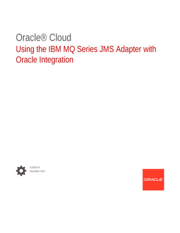
Trusted Communication Interface Adapter2. Description2. DescriptionFigure 1 T8153 PhotoThe Trusted Communication Interface Adapter T8153 is designed to be connected directly tothe rear of a Trusted Communication Interface Module in a Trusted Controller ChassisT8100. The Assembly provides a communications connection interface to remote systems.Connection between the Assembly and the Trusted Communication Interface module is viaa 78 2-way Inverse DIN41612 M-type connector (SK1).Figure 2 shows the physical layout of the Assembly with a side plate removed.Rockwell Automation Publication PD T8153Issue 145
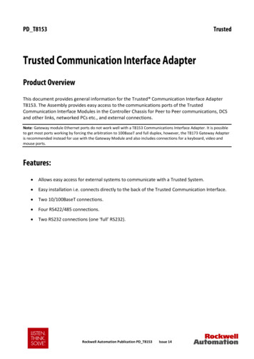
2. DescriptionTrusted Communication Interface AdapterFigure 2 Assembly LayoutThe Assembly comprises a printed circuit board (PCB) on which the communications portsand socket SK1 (connector to the Trusted Communication Interface) are mounted. TheAssembly is contained within a metal enclosure and is designed to be clipped onto theappropriate connector at the rear of the Controller Chassis. A release button is provided toenable the Assembly to be disconnected.The communications ports available at the Assembly are RS232 (one each of full andpartial), RS485 (both direct and multi-drop) and Ethernet (10BaseT and 100BaseT).2.1. RS232 Serial PortsThere are two connectors available to access the RS232 ports. Bank 1 provides a full RS232interface. Bank 2 provides a partial RS232 interface with connections limited to TX, RX, RTSand CTS.6Issue 14Rockwell Automation Publication PD T8153
Trusted Communication Interface Adapter2. Description2.2. RS485 Serial Ports1. There are eight connectors available to directly access the four RS485 ports. Banks 1and 2 cannot be used in the RS485 mode if the Trusted Communication Interface isconfigured for RS232 on these ports.2. The RS485 ports are provided with two connectors per port. Each port is providedwith link selectable 120 Ω alternating current (ac) termination on both the transmitand receive circuits as shown in the table below.BankConnector 1Connector 2TX Term. LinkTX/RX Term. LK4Table 2 Configuration for Multiplexed Links3. The ac coupled termination is used so as to reduce the current drawn on thetransmission line during the idle state. The use of two connectors and link selectabletermination is to make the configuration of multiplexed transmission lines simpler.This method also provides the termination close to the transceivers thus avoidingunnecessary reflections on the line.2.3. ExamplesRS485 FULL DUPLEX LINKThis is a point to point 4 wire link. The connections to the Termination Assembly should beto Connector 1 with the TX/RX Termination link fitted.RS485 FULL DUPLEX MULTIPLEXEDThis is the most complicated system.If the Termination Assembly is at the start of the multiplexed chain then Connector 1 is usedand the TX/RX Termination link is fitted.If the Termination Assembly is in the chain then the Connector 1 is used to connect thechain in and connector 2 is used to wire out to the next device. No links are fitted for thisport.If the Termination Assembly is the last device in the chain Connector 1 is used and both theTX Termination Link and the TX/RX Termination Link are fitted. The TX Termination link isRockwell Automation Publication PD T8153Issue 147
2. DescriptionTrusted Communication Interface Adapterused here so that both ends of the line with multiple transmitters connected areterminated.RS485 Half Duplex MultiplexedThis is the 2 wires 485 system that is only wired on the RX/TX wires.If the Termination Assembly is at the start or end of the transmission line Connector 1 isused and the TX/RX Termination link is fitted.If the Termination Assembly is in the transmission line then Connector 1 is used to connectthe chain in and Connector 2 is used to wire out to the next device. No links are fitted forthis port.2.4. RS485 HintsThe signal ground on the RS485 links must always be connected otherwise thecommunications between the devices may be unreliable. When specifying cable for theseconnections allowance should be made for the signal ground connection. If screened cableis used the signal ground should not be connected to the screen. It is usual to connect thescreen to the chassis earth at one end only.Some manufacturers tend to use and – designations on their equipment for labelling thepairs. Since there is no standard as to how these match up with the EIA circuit designatorsthe following may be useful:With the transmission line in the ‘Idle’ or ‘Off’ state connect a multimeter on thevolts range across the pair. When the multimeter reads a negative voltage the veterminal of the multimeter is connected to A and the –ve terminal is connected to B.2.5. Ethernet portsEthernet ports 1 (TCP/IP 0) on J6 and 2 (TCP/IP 1) on J8 are provided with connections to10/100BaseT networks via RJ45 connectors.8Issue 14Rockwell Automation Publication PD T8153
Trusted Communication Interface Adapter3. Installation3. Installation3.1. Communications InterfaceWhen connecting to the chassis connect the socket with the rear of the chassis and slide upuntil it mates and clicks into place. The Communications Interface needs to be removed.3.1.1.Connector (SK1)SK1 is a 78 2-way DIN41612, Inverse M-type connector.CONNECTOR SK1 323191613Rockwell Automation Publication PD T8153Issue 149
3. InstallationTrusted Communication Interface AdapterCONNECTOR SK1 PINOUTPinABC12P1 TD P1 TD-11P1 RD P1 RD-10CHASSIS GND98P2 TD P2 TD-7P2 RD P2 RD-6CHASSIS GND54LINKTable 3 SK1 Connector Pin-out3.1.2.External Connector Full RS232 bank 1 (J3)J3 is a Phoenix contact 2.5mm pitch TR9RITable 4 Connector J3 Pin-out10Issue 14Rockwell Automation Publication PD T8153
Trusted Communication Interface Adapter3.1.3.3. InstallationExternal Connector Partial RS232 Bank 2 (J7)J7 is Phoenix contact 2.5 mm pitch connector.PinService1TXD2RXD3RTS4CTS5GNDTable 5 Connector J7 Pin-out3.1.4.External Connectors RS485 Banks 1 to 4 (J4, J5, and J9 to J14)These are Phoenix 2.5 mm pitch le 6 Connectors J4,5 and 9-14 Pin-out3.1.5.External Connectors 10/100BaseT (J6 & J8)These are RJ45 connectors.PinService1TD 2TD-3RD 4Rockwell Automation Publication PD T8153Issue 1411
3. InstallationTrusted Communication Interface AdapterPinService56RD-Table 7 Connectors J6 and J8 Pin-out3.2. Gateway ModuleThe Communication Interface Adapter is not recommended for use with the T8170 GatewayModule. The T8173 Adapter is recommended for this purpose. It provides better transportof the Ethernet wiring and keyboard, video and mouse ports.3.3. Mating ConnectorsThe following table gives a list of connectors required to interface to the TrustedCommunication Interface Adapter (T8153). Note the module is delivered with the PhoenixContact parts fitted:ConnectionManufacturerPart NumberJ3 (9 - way socket)Phoenix Contact18 81 39 6J4, J5, J7, J9, J10, J11, J12, J13, J14(5 - way socket)Phoenix Contact18 81 35 4J6 & J8 * (RJ45 Items marked * show a selection of manufacturers for these parts as examples only, others can beused.Table 8 Mating ConnectionsNotes: An earth point is provided on the PCB of the Assembly so that the chassis earth of the TrustedCommunication Interface is connected to both the enclosure and module rack earth.12Issue 14Rockwell Automation Publication PD T8153
Trusted Communication Interface Adapter4. Specifications4. SpecificationsPorts(when connected to CommunicationInterface)RS2322-off (one full RS232 and one partial RS232)RS4854-off (with direct and multi-drop facilities)Ethernet2-off (10BaseT or 100BaseT)Operating Temperature0 C to 60 C ( 32 F to 140 F)Non-operating Temperature-25 C to 70 C (-13 F to 158 F)Relative Humidity range(operating, storage & transport)10 % – 95 %, non-condensingEnvironmental SpecificationsRefer to Document 552517DimensionsHeight150 mm (5.9 in)Width28 mm (1.1 in)Depth (including mounting rail)106 mm (4.2 in)WeightRockwell Automation Publication PD T8153418 g (0.92 lb.)Issue 1413
The Trusted Communication Interface Adapter T8153 is designed to be connected directly to the rear of a Trusted Communication Interface Module in a Trusted Controller Chassis T8100. The Assembly provides a communications connection interface to remote systems. Connection between the Assembly and the Trusted Communication Interface module is via