Transcription
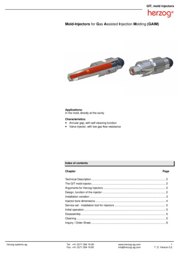
GIT, mold injectorsMold-Injectors for Gas Assisted Injection Molding (GAIM)Applications:In the mold, directly at the cavityCharacteristics: Annular gap, with self cleaning function Valve injector, with low gas flow resistanceIndex of contentsChapterPageTechnical Description . 2The GIT mold injector. 2Arguments for Herzog injectors . 2Design, function of the injector . 2Installation variation . 3Injector bore dimensions . 4Service set - installation tool for injectors . 5Initial operation . 5Disassembly. 5Cleaning. 5Inquiry / Order Sheet. 6herzog systems agTel. 41 (0)71 394 19 69Fax. 41 (0)71 394 19 60www.herzog-ag.cominfo@herzog-ag.com1T. D. Version 0.2
GIT, mold injectorsTechnical descriptionProcess: Short shot Full shot Gas cooling / Gas rinsingGas injection technologyWith gas injection technology, gas is injected into the plastic melt at the end of the injecting process. The injected gas displaces the melt on the inside thus resulting in a cavitybeing formed. Short shot, cavity is partially filled with plastic melt. The plastic melt is pressedagainst the mold wall with the injected fluid.Advantages: Cycle time reduction Contact force reduction Flexible installation Rigidity Light weight Low distortion Good surface quality No sunken areas Full shot, entire cavity is filled with plastic melt. The injected fluid forces the melt intoan adjoining cavity. Full shot back pressure procedure, entire cavity is filled with plastic melt. The injected fluid forces the melt through the sprue bushing back into cylinder vestibule.The GIT mold injectorGas injectors are installed directly into the mold. One or more injectors are assembledinto the mold, depending of the size and geometry of the molded part as well as the fluidity of the melt.With an installation either parallel or diagonal to the form direction, the mold injector mustbe used with an extraction mechanism.Arguments for Herzog injectorsSealing boltPinSleeve Small dimensionsBack-gassing (gas pressure release)Ensures high process stabilitySelf cleaning functionLow maintenanceAssembly / disassembly at the mold interface levelDesign and function of the injectorThe regulated gas, usually nitrogen, is fed through drillings in the mold to the injector andthrough this into the molded part. The back-gassing or gas pressure release goesthrough the same injector back into the supply.The gassing of the cavity is only possible when the gas injection pressure is higher thanthe opposing pressure in the cavity. The gas injection pressure moves the pin whichopens the injector completely, allowing for high volumes to be achieved.The back-gassing goes through cross-shaped surfaces on the sealing area of the pin.The gap is large enough to allow the gas to flow through, but small enough to prevent themelt from seeping in.Maintenance of the injector can be carried out simply and quickly when the mold is open.herzog systems agTel. 41 (0)71 394 19 69Fax. 41 (0)71 394 19 60www.herzog-ag.cominfo@herzog-ag.com2T. D. Version 0.2
GIT, mold injectorsInstallation variationInstalled directly in the moldThe injector opening is directly in the mold.Gassing occurs by means of drill holes in the mold plate.PUsing a mounting and conduitThe injector opening is in a mounting which is allowed into the mold.A conduit runs from the injector mounting through the mold to the interface block.Interface blockPConduitLocking nutCavityherzog systems agInjectorMountingTel. 41 (0)71 394 19 69Fax. 41 (0)71 394 19 60Spacing tubewww.herzog-ag.cominfo@herzog-ag.com3T. D. Version 0.2
GIT, mold injectorsInjector bore dimensionsMold Injector M6 thread. Dimensions in mm.10,5 / M612,5 / ø512 / M4x0.513,5 / ø3.55510ø6 H6Fit length 4Insert sealing conemax. ø1,890 Mold Injector M4x0.5 thread - sealing lip on mold plate. Dimensions in mm.ø645 65110ø4 H6Fit lenght 5Insert sealing conemax. ø1,890 Mold Injector M4x0.5 thread - sealing lip on separate casing. Dimensions in mm.13,5 / ø3.512 / M4x0.56510ø6 H6Fit length 5Insert sealing conemax. ø1,890 herzog systems agTel. 41 (0)71 394 19 69Fax. 41 (0)71 394 19 60www.herzog-ag.cominfo@herzog-ag.com4T. D. Version 0.2
GIT, mold injectorsService set - Torque wrench for Injectors / Initial operationThe injector is an accurately manufactured component which requires skilled handling.Suitable tools should be selected for assembly and cleaning. For this purpose, we recommend our service set.Initial operationAttention:Do not heat injector above 400 C.Injector is sensitive to blows and lateral forces.Installation1. Check that the thread, sealing surface and sleeve are intact (free of damage and dirt).2. Make sure that the injector is provided with a pin. The pin must not protrude from theinjector housing at the thread end.3. The following torques are necessary to fix the injector into the mold:max. torque 2 Nm (200Ncm)Disassembly - Removing the pin from the injectorA)B)Torque wrenchInjectorCapScrew the injector into the capC)CapScrew cap fully into the torque wrench as indicatedD)Loosen cap and remove with injector bushing andextracted pin.Cleaning without service setherzog systems ag The cleaning of the injector must be carried out with care. Overheating or excessive mechanical wear (filing, polishing) can prevent the injector from function. The sealing bolt and the internal pin can normally be removed towards the thread.The internal pin may be ejected with a 1.9 mm diameter drift. Cleaning the pin takes place by rubbing off the deposits. The cleaning of the housing (sleeve) is carried out as follows: use a 2 H6reamer and turn carefully and lightlyCaution: Introduce the reamer from the injector thread end and turn slightly. Injectors which are contaminated with thermoplastics are cleaned in a fluidizedbed bath or an ultrasonic reaction vessel.Tel. 41 (0)71 394 19 69Fax. 41 (0)71 394 19 60www.herzog-ag.cominfo@herzog-ag.com5T. D. Version 0.2
GIT, mold injectorsDimension Sheet for enquiryor orderGIT Mold-InjectorsCompany:Contact person:Street:Tel.:City / Zip:Fax:Land:E-Mail:Standard dimensionsGIT Mold InjectorAssembly threadM6M4x0.5Integrated as standardNot integrated / OptionalØ 4.6mmØ 4mmInjector cavity immersion depth5mm or 10mm5mm or 10mmGas withdrawal through injectorStandardStandardSealing lipInjector opening in the molded partPlease checkGIT mold injectorM6M4x0.5GIT mold injector length in mm5Sealing lipIntegrated on the injectorOptional sealing lip casingGIT service set *M6 Service setM4x0.5 Service set10510* We recommend using our specially designed tool for installation and cleaning.Service setNote: Technical modifications reserved. We need additional information for requirements, which vary from our standard range e.g. drawing sample. Our customer serviceswill be pleased to help you.herzog systems agTel. 41 (0)71 394 19 69Fax. 41 (0)71 394 19 60www.herzog-ag.cominfo@herzog-ag.com6T. D. Version 0.2
The injected gas displaces the melt on the inside thus resulting in a cavity being formed. Short shot, cavity is partially filled with plastic melt. The plastic melt is pressed against the mold wall with the injected fluid. Full shot, entire cavity is filled with plastic melt. The injected fluid forces the melt into an adjoining cavity.