Transcription
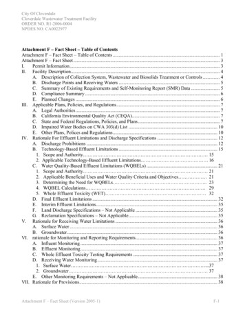
The Presby WastewaterTreatment SystemMontanaDesign and Installation ManualforAdvanced Enviro-Septic Wastewater Treatment SystemMinimizes the ExpenseProtects the EnvironmentPreserves the SitePresby Environmental, Inc.The Next Generation of Wastewater Treatment Technology143 Airport Rd., Whitefield, NH 03598Tel: 800-473-5298 Fax: tal.com Copyright October 2016, Presby Environmental, Inc., All Rights Reserved.
The information in this manual is subject to change without notice. We recommend that you check your State’s pageon our website on a regular basis for updated information. Your suggestions and comments are welcome.Presby Environmental, Inc.143 Airport RoadWhitefield, NH 03598Phone: 1-800-473-5298 Fax: (603) 837-9864Website: www.PresbyEnvironmental.comThe products and methods depicted in this manual are protected by one or more patents. For more information:Pat. www.presbyeco.com/patentsAdvanced Enviro-Septic is a registered trademark of Presby Environmental Inc.IMPORTANT NOTICE: This Manual is intended ONLY for use in designing and installing Presby Environmental’sAdvanced Enviro-Septic Wastewater Treatment Systems. The use of this Manual with any other product is prohibited.The processes and design criteria contained herein are based solely on our experience with and testing of AdvancedEnviro-Septic and Simple-Septic . Substitution of any other large diameter gravelless pipe will result in compromisedtreatment of wastewater and other adverse effects. Presby Environmental, Inc. October 2016All Rights ReservedDate of Issue: October 17, 2016
TABLE OF CONTENTSSection NumberPage Number1.0Background .12.0Ten Stages of Wastewater Treatment.23.0System diagram .34.0Presby System Components.45.0Table A: Application Rates by Soil Texture and Percolation Rates; System Sand Bed Area .66.0Table B: System Limitations & Presby Pipe Requirement.67.0Table C: Row Length and Pipe Layout Width .78.0Design Procedure and Examples .79.0Presby Environmental Standards and Technical Support . 1010.0Certification Requirements . 1011.0Design Criteria . 1012.0Basic Serial Distribution . 1213.0Combination Serial Distribution . 1314.0D-Box Distribution (Single Level) . 1415.0Multiple Bed Distribution . 1416.0Angled and Curving Beds . 1517.0Elevated Bed Systems (Mounds) . 1518.0In-Ground Bed Systems . 1619.0Non-Conventional System Configurations . 1620.0Pumped System Requirements . 1621.0Venting Requirements. 1722.0Site Selection . 2023.0Installation Requirements, Component Handling and Site Preparation . 2124.0System Bacteria Rejuvenation and Expansion . 2325.0System Expansion . 2326.0Operation & Maintenance . 2327.0Glossary . 24 Presby Environmental, Inc., Montana Design & Installation Manual, October 2016 Edition-i-
1.0 BackgroundLiquid that exits from a septic tank (“effluent”) contains suspended solids that can cause traditional systems to failprematurely. Solids can overload bacteria, cut off air required for aerobic bacterial activity, and/or seal the underlyingsoil, interfering with its ability to absorb liquid.1.1What Our System DoesBy utilizing simple yet effective natural processes, the Presby Treatment System treats septic tank effluent in amanner that prevents suspended solids from sealing the underlying soil, increases system aeration, and provides agreater bacterial treatment area (“biomat”) than traditional systems.1.2Why Our System ExcelsThe Presby Treatment System retains solids in its pipe and provides multiple bacterial surfaces to treat effluent priorto its contact with the soil. The continual cycling of effluent (the rising and falling of liquid inside the pipe) enhancesbacterial growth. This all combines to create a unique eco-system that no other passive wastewater treatmentsystem is designed to offer. The result is a system that excels by being more efficient, lasting longer, and having aminimal environmental impact.1.3System Advantagesa) costs less than traditional systemsb) eliminates the need for washed stonec) often requires a smaller aread) installs more easily and quickly than traditional systemse) adapts easily to residential and commercial sites of virtually any sizef) adapts well to difficult sitesg) develops a protected receiving surface preventing sealing of the underlying soilh) blends “septic mounds” into sloping terraini) increases system performance and longevityj) tests environmentally safer than traditional systemsk) recharges groundwater more safely than traditional systemsl) made from recycled plastic1.4Patented Presby TechnologyAt the heart of Advanced Enviro-Septic is a patented corrugated, perforated plastic pipe with interior skimmer tabsand cooling ridges. All Presby Pipe is surrounded by one or more filtering, treatment and dispersal layers. PresbySystems are completely passive, requiring no electricity, motors, alarms, computers, etc. Presby Pipes areassembled and installed in a bed of specified System Sand which can either be below the ground or above.1.5Advanced Enviro-Septic (AES)The Advanced Enviro-Septic pipe is assembled into an onsite wastewater treatment system that has beensuccessfully tested and certified to NSF 40, Class I (a certification typically given to mechanical aeration devices),BNQ of Quebec, Class I, II, III and Cebedeau, Belgium standards. Advanced Enviro-Septic is comprised ofcorrugated, perforated plastic pipe, Bio-Accelerator fabric along its bottom which is surrounded by a layer ofrandomized plastic fibers and a sewn geo-textile fabric. Advanced Enviro-Septic creates an eco-system designed tosimultaneously purify and disperse effluent after primary treatment by a septic tank. Advanced Enviro-Septic is the“next generation” of our Enviro-Septic technology. The AES product incorporates Bio-Accelerator , a proprietaryenhancement that screens additional solids from effluent, accelerates treatment processes, assures even distributionand provides additional surface area. Each foot of Advanced Enviro-Septic pipe provides over 40 sq ft of totalsurface area for bacterial activity. Presby Environmental, Inc., Montana Design & Installation Manual, October 2016 Edition-1-
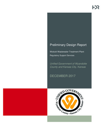
2.0Ten Stages of Wastewater TreatmentThe Presby Wastewater Treatment System10 Stages of Advanced Enviro-Septic (AES) TreatmentSEWN SEAM(ALWAYS UP)AIR SPACE101SCUM2EFFLUENT2SLUDGE SYSTEM SANDCROSS SECTION8 9734GEO-TEXTILEFABRIC6COARSEFIBERSSKIMMER TABS5RIDGESBIO-ACCELERATOR FABRICStage 1:Warm effluent enters the pipe and is cooled to ground temperature.Stage 2:Suspended solids separate from the cooled liquid effluent.Stage 3:Skimmers further capture grease and suspended solids from the existing effluent.Stage 4:Pipe ridges allow the effluent to flow uninterrupted around the circumference of the pipe and aid incooling.Stage 5:Bio-Accelerator fabric screens additional solids from the effluent, enhances and accelerates treatment,facilitates quick start-up after periods of non-use, provides additional surface area for bacterial growth,promotes even distribution, and further protects outer layers and the receiving surfaces so they remainpermeable.Stage 6:A mat of coarse, randomly oriented fibers separates more suspended solids from the effluent.Stage 7:Effluent passes into the geo-textile fabrics and grows a protected bacterial surface.Stage 8:Sand wicks liquid from the geo-textile fabrics and enables air to transfer to the bacterial surface.Stage 9:The fabrics and fibers provide a large bacterial surface to break down solids.Stage 10:An ample air supply and fluctuating liquid levels increase bacterial efficiency. Presby Environmental, Inc., Montana Design & Installation Manual, October 2016 Edition-2-
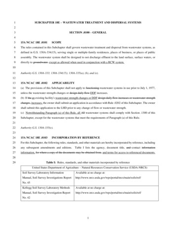
3.0System diagramNotes:1. All rows spaced 2 ft center-to-center minimum2. Rows grouped in middle of System Sand bed for level fields.3. Venting required for all configurations Presby Environmental, Inc., Montana Design & Installation Manual, October 2016 Edition-3-
4.0Presby System Components4.1Advanced Enviro-Septic Pipea) Plastic pipe made with a significant percentage of recycled materialb) 10 ft sections (can be cut to any length)c) Ridged and perforated, with skimmer tabs on interiord) Bio-Accelerator along bottom of pipe (sewn seam is always placed up).e) Surrounded by a mat of randomly-oriented plastic fibersf) Wrapped in a non-woven geo-textile fabric stitched in placeg) Exterior diameter of 12 in.h) Each 10 ft section has a liquid holding capacity of approx. 58 gallonsi) A 10 ft length of AES pipe is flexible enough to bend up to 90 4.2Component Handling & CareThe outer fabric of the Presby pipe is ultra-violet stabilized; however, this protection breaks down after a period oftime in direct sunlight. To prevent damage to the fabric, cover the pipe with an opaque tarp.a) Keep mud, grease, oil, etc. away from all components.b) Avoid dragging pipe through wet or muddy areas.c) Store pipe on high and dry areas to prevent surface water and soil from entering the pipes orcontaminating the fabric prior to installation.4.3CouplingA coupling is a plastic fitting used to create a connection between two pieces of Presby Pipe.Note that the couplings are wide enough to cover 1 or 2 pipe corrugations on each of the twopipe ends being joined. The couplings feature a snap-lock feature that requires no tools.When assembling pipes into rows, note that the geo-textile fabric does not go under couplings.Pull fabric back, install coupling, and then pull fabric over coupling. Also note, duringinstallation in cold weather, couplings are easier to work with if stored in a heated location(such as a truck cab) before use.4.4Double Offset AdapterA double offset adapter is a plastic fitting 12 in. in diameter with two 4 in. holes designed toaccept a 4 in. inlet pipe, raised connection, vent or vent manifold, and/or bottom drain,depending upon the particular requirements of the design configuration. The 4 in. holes are tobe aligned in the 12 o’clock and 6 o’clock positions. The holes are positioned 1 in. from theoutside edge of the double offset adaptor and 2 in. from each other.4.5Distribution BoxA Distribution Box, also called a “D-box,” is a device used to distribute effluent coming from the septic tank in asystem that contains more than one section or more than one bed. D-boxes are also sometimes used for velocityreduction. D-boxes come in various sizes and with a varying number of outlets. Concrete D-boxes are preferred;some are made of plastic. Flow equalizers (see below) are installed in the D-box openings to equalize distribution;they help ensure equal distribution in the event that the D-box settles or otherwise becomes out of level. Unusedopenings in D-boxes are to be covered, plugged or mortared.4.6Flow EqualizersAll Presby Systems with Combination Serial distribution or Multiple Bed distributionmust use Flow Equalizers in each distribution box outlet. A flow equalizer is anadjustable plastic insert installed in the outlet holes of a distribution box to equalizeeffluent distribution to each outlet whenever flow is divided. Each Bed or section ofCombination Serial distribution is limited to a maximum of 15 gallons per minute, due tothe flow constraints of the equalizers. Example: pumping to a combination system with 3sections (using 3 D-Box outlets). The maximum delivery rate is (3 x 15) 45 GPM.Always provide a means of velocity reduction when needed.4.7Offset AdapterAn offset adapter is a plastic fitting 12 in. in diameter with an inlet hole designed to accept a 4inch sewer line, raised connection or vent pipe. The hole is to be installed in the 12 o’clockposition. The distance from the bottom of the Offset Adapter to the bottom of its inlet hole is 7in. When assembling pipes into rows, note that the geo-textile fabrics are placed over the edgesof the Offset Adapter and Couplings. Presby Environmental, Inc., Montana Design & Installation Manual, October 2016 Edition-4-
4.8Manifolded Splitter BoxA manifolded splitter box joins several outlets of a D-box to help divide flow moreaccurately (see illustration to right). Dividing flow to multiple beds is a common use ofsplitter boxes. All outlets delivering effluent to the Presby field must have a flow equalizer.Do not place an equalizer on vent outlets.4.9Raised ConnectionA raised connection is a PVC Sewer & Drain pipe configuration which is used to connectPresby Rows. Raised connections extend 2 in. to 4 in. into pipe and are installed on anangle (as shown below). All PVC joints should be glued or mechanically fastened.4.10 Raised Straight ConnectionA raised straight connection is a PVC Sewer & Drain pipe configuration which is used to connect Presby Rows thatare placed end to end along the same contour. Raised straight connections extend 2 in. to 4 in. into pipe and areinstalled on an angle (as shown below). All PVC joints should be glued or mechanically fastened. Offset Adapters willaccept 4 inch schedule 40 PVC if the edge to be inserted into the adapter is rounded.4.11 Septic TankThe Advanced Enviro-Septic System is designed to treat effluent that has received “primary treatment” in astandard septic tank. Septic tank capacity should be in accordance with state and local regulations. In addition:a) System must be fitted with inlet and outlet baffles in order to retain solids in the septic tank and to preventthem from entering the Advanced Enviro-Septic .b) Effluent filters on septic tank outlets are required by state rules.c) The effluent filter selected must allow the free passage of air to ensure the proper functioning of the systemand maintained properly.4.12 System SandThe System Sand that surrounds the Advanced Enviro-Septic pipes is an essential component of the system. It iscritical that the correct type and amount of System Sand is used during construction. System Sand must be coarseto very coarse, clean, granular sand, free of organic matter. System Sand is placed a minimum of 6 in. below pipesand between rows; and a minimum of 3” above the pipes. It must adhere to all of the following percentage andquality restrictions:Presby System Sand SpecificationSieve SizePercent Retained on Sieve (by weight)3/4 in. (19 mm)0#10 (2 mm)0 - 35#35 (0.50 mm)40 - 90Note: not more than 3% allowed to pass the #200 sieve (verified by washing sampleper requirements of ASTM C-117)4.13 System Sand Acceptable AlternativeASTM C-33 (concrete sand), natural or manufactured sand, with not more than 3% passing the #200 sieve (verifiedby washing the sample per the requirements of ASTM C-117 as noted in the ASTM C-33 specification) may be usedas an acceptable alternate material for use as System Sand. Presby Environmental, Inc., Montana Design & Installation Manual, October 2016 Edition-5-
5.0Table A: Application Rates by Soil Texture and Percolation Rates; System Sand Bed oadingRate (ALR)(gpd/ft²) 30.83-5Gravelly Sand orvery coarsesandsLoamy sand,coarse sandMedium sand,sandy loamFine sandy loam,loam, silt loamVery fine sand,sandy clay loamClay loam, siltyclay loamSandy clay, clayor silty clayClays, silts, siltyclays (Soil isreportedthroughout thesoil profile) (UseEVTA BED)Clays or silts,pan evaporationrates do not allowfor EVTA useSystem Sand Bed Area (sq ft)by Number of Bedrooms2345Add’l225 GPD300 GPD350 GPD400 GPD50 50(3)120 Not Permitted1Percolation (perc) tests may be required to help distinguish between types of clays and compacted silts and their permeability as aresult of mineralogy, structure, compactness and other factors. If the local reviewing authority has experience with the soil typeencountered, the percolation test may be waived and the application rate provided in the table may be used. If percolation ratesare faster than the estimate shown the application rate provided in the appropriate column must be used as the maximum. (Inother words, use the most conservative of the two, either soil texture or percolation rates).2To conform with Circular DEQ 4 section 4.2.3.3, systems requiring over 500 sq ft of sand bed area (after reductions) may requiremultiple beds to avoid pressure distribution which is not allowed or needed with this technology.3To conform with Circular DEQ 4 section 4.2.3.3, systems requiring over 750 sq ft of sand bed area (after reductions) may requiremultiple beds to avoid pressure distribution which is not allowed or needed with this technology.6.0Table B: Presby Pipe Requirement & Slope LimitationsPercolation RateMinutes per Inch(MPI)15 or less16-3031-4041-5051 – 6061 - 120Presby Pipe perBedroomMinimum*(ft)506070707070% System SlopeMaximum% Site SlopeMaximum2525201510030302520155* Presby pipe requirement for commercial systems calculated at 1 ft for every 2 GPD of design flow. Ex: 300 GPD commercialdesign flow requires 150 ft of Presby pipe (300 2). Pipe requirements for both residential and commercial systems assumesnormal strength wastewater. Contact Presby Environmental for recommendations for higher strength effluent. Presby Environmental, Inc., Montana Design & Installation Manual, October 2016 Edition-6-
7.0Table C: Row Length and Pipe Layout WidthTotal Linear Feet of Presby 0505256006757508259009751,050 1,1255606407208008809601,040 1,120 1,2005956807658509351,0201,105 1,190 1,2756307208109009901,0801,170 1,260 1,3506657608559501,0451,1401,235 1,330 1,4257008009001,000 1,1001,2001,300 1,400 1,50078910111213141513.00 15.00 17.00 19.00 21.0023.0025.00 27.00 29.0014.50 16.75 19.00 21.25 23.5025.7528.00 30.25 32.5016.00 18.50 21.00 23.50 26.0028.5031.00 33.50 36.0017.50 20.25 23.00 25.75 28.5031.2534.00 36.76 39.5019.00 22.00 25.00 28.00 31.0034.0037.00 40.00 43.0020.50 23.75 27.00 30.25 33.5036.7540.00 43.25 46.5022.00 25.50 29.00 32.50 36.0039.5043.00 46.50 50.0023.50 27.25 31.00 34.75 38.5042.2546.00 49.75 53.5025.00 29.00 33.00 37.00 41.0045.0049.00 53.00 57.00Pipe Layout Width ftEx: Select a row length and move right until the minimum amount of pipe is found (more is allowed). Then move down to find thenumber of rows required; continue downward in the same column to find the pipe layout width for your spacing.C/L (ft)Row Length (ft)20253035404550556065707580859095100# n Procedure and ExamplesStep #1: From Table A: using the soil’s percolation rate and find the minimum System Sand Bed Area (SSBA)required from Table A. This can be calculated manually by dividing the daily design flow by the soil’s ApplicationLoading Rate (ALR). System over 1,000 sq ft (before reductions) may require additional beds (see Table A).Step #2: Calculate the minimum amount of Presby Pipe needed (assumes normal strength wastewater):a) Residential systems multiply number of bedrooms by Presby pipe required from Table B for system’s soilsb) Commercial systems divide daily design flow by 2 GPD/ft (round up to the nearest whole numberStep #3: From Table B: choose an allowable system slope.Step #4: Calculate the minimum number of serial sections required (does not apply to Parallel configuration): dividethe daily design flow by 600 GPD (round up to nearest whole number).Step #5: Select a row length suitable for the site and calculate the number of rows (round up to a whole number).The number of rows must be evenly divisible by the number of serial sections required (add rows as necessary).Step #6: Find the Pipe Layout Width (PLW) from Table C using a 2 ft minimum center-to-center row spacing (largerspacing allowed).Step #7: Calculate the minimum System Sand Bed Width (SSBW) by dividing the System Sand Bed Area from Step#2 by the selected row length from Step #5 1ft (allows 6 inches of sand beyond the ends of the rows).Step #8: Verify the minimum SSBW from Step #7 will cover all the rows in the bed:a) Beds sloping 0 - 5%: If the minimum SSBW is less than the (PLW 1 ft), use (PLW 1 ft) as the newminimum SSBW.b) Beds sloping 5%: If the minimum SSBW is less than the (PLW 3.5 ft), use (PLW 3.5 ft) as the newminimum SSBW. Adding 3.5 ft to the pipe layout width accounts for a 2.5 ft System Sand Extension on thedown slope side of the field.Step #9: Calculate System Sand Extension(s):a) Level beds: System Sand Extension (SSE) are placed on each side of Presby Pipes [SSBW – (PLW 1)] 2. There will be no SSE’s if the SSBW (PLW 1 ft).b) Sloping Beds: SSE placed entirely on the down slope side of the bed SSBW – (PLW 1) and must be atleast 2.5 ft (3 ft from the edge of the Presby Pipe) if system slope is over 5%.Step #10: Verify center-to-center distance of the first and last rows is not more than 14 ft, if so use multiple beds. Presby Environmental, Inc., Montana Design & Installation Manual, October 2016 Edition-7-
8.1Design Example #1 (residential)Single-family residence, 4 bedrooms (350 GPD), percolation rate: 15 MPI (fine sandy loam), level site, serialdistribution layout if allowed.Step #1: System Sand Bed Area from Table A: 350 GPD 1.0 GPD/sq ft ALR 350 sq ft ( 500 sq ft single bed)Step #2: Presby Pipe required at 15 MPI per Table B: 4 bedrooms x 50 ft/bedroom 200 ft minimum.Step #3: Level site, no need to slope this system.Step #4: Serial sections required 350 GPD 600 GPD/section 0.59, round up to 1, which is a basic serial systemStep #5: Using a row length of 50 ft requires four rows (200 ft 50 ft 4 rows).Step #6: Table C shows a PLW of 7.0 ft when using four 50 ft long rows spaced at 2 ft center-to-center.Step #7: Minimum SSBW 350 sq ft (50 ft 1 ft) 6.9 ft.Step #8: a) 8 ft SSBW to cover all the Presby pipes (7 ft PLW 1 ft) is greater than 6.9 ft minimum sand bed width tosatisfy the sand bed area requirement. Must us the larger of the two values 8 ft b) not required.Step #9: a) System Sand Extensions SSBW – (7 ft PLW 1 ft) 0, so there will not be any System Sandextensionsb) not required.Step #10: Center-to-center distance between first and last rows is 6 ft, which does not exceed 14 ft, bed okIllustration of Example #1, Basic Serial Distribution:8.2Design Example #2 (residential):Single-Family Residence, 5 bedrooms (400 GPD), 30 MPI soils (sandy clay loam), design for a 12% sloping systemas an elevated bed.Step #1: Sand Bed Area from Table A 500 sq ft ( 500 sq ft single bed)Step #2: Presby pipe required at 30 MPI per Table B: 5 bedrooms x 60 ft/bedroom 300 ft minimumStep #3: Table B allows up to 25% system slope for 30 MPI and our system will only slope 12%Step #4: Serial sections required 500 GPD 600 GPD/section 0.84, round up to 1 (Basic Serial System)Step #5: Using a row length of 75 ft requires four rows (300 ft 75 ft 4 rows)Step #6: Table C shows a PLW of 7 ft when using four 75 ft long rows spaced at 2 ft center-to-center.Step #7: Minimum SSBW 500 sq ft (75 ft 1 ft) 6.6 ftStep #8: a) system slope greater than 5%. b) 6.6 ft SSBW is less than (7 ft PLW 3.5 ft 10.5 ft); use 10.5 ft as thenew SSBW.Step #9: a) system slope greater than 5%. b) System Sand extension 10.5 ft SSBW – (7 ft PLW 1 ft) 2.5 ft andplaced entirely on the down slope side of the field.Step #10: Center-to-center distance between first and last rows is 6 ft, which does not exceed 14 ft, bed okSee illustration of Example #2 on next page. Presby Environmental, Inc., Montana Design & Installation Manual, October 2016 Edition-8-
Illustration of Example #2, Basic Serial Distribution:8.3Design Example #3 (commercial):Commercial system to treat 650 GPD, 31 MPI soils (clay loam), level bed.Step #1: Sand Bed Area from Table A 650 GPD 0.6 GPD/sq ft 1,084 sq ft [requires multiple beds to conform toCircular DEQ 4, section 4.2.3.3 (1,084 ft2 500 ft2 2.17 round up to 3 beds)]Step #2: Presby pipe required 650 GPD 2 GPD/ft 325 ft minimum (325 3 beds 108.4 ft, round up to 110 ftper bed)Step #3: Level site, no need to slope this system.Step #4: Serial sections required (650 GPD 3 beds) 600 GPD/section 0.36, round up to 1 section per bed)Step #5: Using a row length of 55 ft requires six rows (325 ft 55 ft 5.9, round up to 6 rows), which will allow 2 rowsper bed.Step #6: Table C shows a PLW of 3 ft per bed, when using two 55 ft long rows spaced at 2 ft center-to-center.Step #7: Minimum SSBW (1,084 sq ft 3 beds) (55 ft 1 ft) 6.46 ft round up to 6.5 ft for ease of construction.Step #8: a) level bed – 6.5 ft SSBW is larger than 4 ft (3 ft PLW 1 ft), so must use 6.5 ft as SSBW.b) not requiredStep #9: a) system level – System Sand extensions (6.5 ft - 4 ft) 2 1.25 ft placed on both sides of pipeb) not requiredStep #10: Center-to-center distance between first and last rows is 2 ft, which does not exceed 14 ft, beds okIllustration of Example #3: Presby Environmental, Inc., Montana Design & Installation Manual, October 2016 Edition-9-
9.0 Presby Environmental Standards and Technical SupportAll Presby Systems must be designed and installed in compliance with the procedures and specifications described inthis Manual and in the product’s state approval. In the event of contradictions between this manual and Montanaregulations, Presby Environmental, Inc. should be contacted for technical assistance at (800) 473-5298.10.0 Certification RequirementsAny designers and installers who have not previously attended a Presby Environmental, Inc. are required to attend aPresby Certification Course. Certification is obtained by attending a Certification Course presented by PresbyEnvironmental, Inc. or its sanctioned representative. Certification can also be obtained by viewing tutorial videos onour website (high speed connection required) and then successfully passing a short assessment test, which is alsoavailable over the internet. All professionals
The Presby Treatment System retains solids in its pipe and provides multiple bacterial surfaces to treat effluent prior to its contact with the soil. The continual cycling of effluent (the rising and falling of liquid inside the pipe) enhances bacterial growth. This all combines to create a unique eco-system that no other passive wastewater .