Transcription
1. Injection Molding1.1 Injection machineThe injection machine is a machine that melt plasticize the molding material inside the heatingcylinder and inject this into the mold tool to create the molded product by solidifying inside it. Theinjection machine is constructed of a mold clamping device that opens and closes the mold tool, anddevice that plasticize and inject the molding material. There are several types in the injectionmachine, and the difference is made by how these two devices are arranged.(1) Horizontal injection machine:Both mold clamping device and injection device compoundedhorizontally(2) Vertical injection machine : Both mold clamping device and injection device compounded vertically(3) Two-color injection machine(4) Rotary injection machine(5) Low foam injection machine(6) Multi material injection machine(7) Sandwich injection machine1.2 Selection of injection machine1.2.1 Select by injection volumeAs a guide, generally the injection machine should be selected so that molded product volume will become 30%to 80% of the machine's injection volume. When molding, the relation of the machine's injection volume Q(g) andone shot weight (sprue and runner weight included) W(g) should be in the range indicated below.Q (1.3 1.5) WIf the injection volume is too small, plasticization will not make it, and might lose its original physicality as amolded product because the resin will be sent without enough plasticization. On the other hand, if the injectionvolume is too big, residence time inside the cylinder will be longer and cause degradation by more chance.1.2.2 Select by mold clamping pressureBoth toggle type and direct pressure type is suitable when molding NOVADURAN. The relation of moldedproduct projected area A(cm2) and required mold clamping pressure P(ton) should be in the range indicatedbelow.P (0.5 0.7) A- 1 -
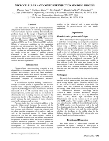
1.2.3 Nozzle structureOpen nozzle is common when molding NOVADURAN. The nozzle of commercially-supplied injection machinecan be open nozzle or shut-off nozzle (Figure 1-1) but in any type, it is necessary to have a temperature control.If drooling from the nozzle is concerned, use the shut-off nozzle. However, it might cause burn and sunspotobject by resin retention at the slide part, so be careful.(A) Open nozzle(B) Shut-off nozzleFigure 1-1 Types and structures of the nozzle1.2.4 Injection mechanismNOVADURAN can be molded by the basic injection machine which has the function of constant injectionspeed and two-stage injection pressure control, but when molding the product which severe measurement,appearance, and moldability (liquidity and demoldability) is required, it is effective to use the machine that has aprogram control of injection speed and injection pressure.1.2.5 Backflow prevention ringBackflow prevention ring is necessary at the screw, because NOVADURAN has relatively low melt viscosity. Ifthis backflow prevention ring is damaged by wear or corrode, cushion volume cannot be kept because of the resinbackflow from the cylinder to the hopper when injecting (pressure keeping), and injection pressure (holdingpressure) might not be put properly to the cavity. In this case, good molded product cannot be made, so cushionvolume and its stability must be well controlled and maintained when molding. Corrosion and abrasion resistancesteel grade is preferable for the back flow prevention ring.1.2.6 Drying machinePreliminary drying is necessary before molding NOVADURAN, and the condition below is general.120 5 8 hours130 4 6 hoursShelf-type hot air circulation dryer, hopper dryer, or dehumidification dryer is preferred when drying. Toprevent the dust and the dirt getting inside, a filter should be placed to air intake of the drying machine, and itsmaintenance against clogging is also necessary.- 2 -
1.3 Molding condition1.3.1 Resin temperatureWhen molding NOVADURAN, resin temperature should be generally about 240 265 . Liquidity will bebetter as the temperature rises, but extremely high temperature will accelerate heat degradation which will endup with physicality deterioration of the molded article.1.3.2 Injection and pressure keeping(1) PressureInjection pressure can be considered as the fill pressure (primary pressure) and the hold pressure (secondarypressure). Generally the fill pressure will be set stronger than the hold pressure. When low-temperaturesolidification, crystalline resin like NOVADURAN will cause a big shrink, therefore the hold pressure isnecessary for filling up and is closely related to the molding shrinkage. Increasing the hold pressure is effective toresolve sink and void problem, but if it increase too much, it might cause burr, so the attention is required.(2) Injection speedIn the case of thin molded product or multi-cavity molded product which severe size precision is required,faster injection speed is better. In contrast, slower injection speed is better for thick molded product. Also, theprogram control of injection speed is effective to resolve the jetting and the flow mark.(3) Injection timeSetting will differ by the molding machine, but basically should be considered as below.injection time (filling time pressure keeping time) gate sealing timeGate sealing time is the time when resin stops flowing by solidification at the gate part. If pressure keeping isput away before the gate is sealed, molten resin will backflow from the gate by the tool internal pressure, whichwill cause measurement and physicality variability, and warpage, sink, and void problems, because of decrease inmolded product's filling density (packing property). To estimate the gate sealing time, measure the weight ofmolded product by gradually increasing the injection time, and look for the injection time when the weight ofmolded became a certain amount and stop changing.1.3.3 Back pressureThe measurement might become instable by the gas and the air generated from molten resin whenplasticization. To stabilize the measurement and improve the kneading effect, put the screw back pressure (5 10kg/cm2) on. However, if the back pressure is too strong, it might degrade the plasticization ability.1.3.4 Mold temperatureGenerally, 60 to 80 is suitable for mold temperature of NOVADURAN, and this is the most important- 3 -
point in the molding condition. If high cycle molding is intended, molding in temperature of about 20 to 30 is possible by using chiller temperature controller, but require attention because it might cause deformation bythe residual strain inside the molded product, and dimension change by aftercontraction might be biggerdepending on the usage environment (high temperature atmosphere). It is effective to raise the mold temperatureto about 120 , when dimension stability is required since assumed to use under a high temperature atmosphere,or high level of surface gloss is necessary.1.4 Preliminary dryingNOVADURAN is a resin with that has relatively low water absorption rate, but if it receives heat history whenit is absorbing water, even a small amount of moisture will cause hydrolysis reaction, and by that molecularweight will decrease which will end up with degrade in physicality. Therefore, moisture must be removed wellenough before molding. Preliminary drying under conditions below is necessary before using.Temperature of hot air120 5 8hours or140 4 6hoursAbout preliminary drying, if the temperature is under 100 it will have no drying effect, and if it is over 140 ,pellet might change its color. Also, if the drying time is set longer than above, it might effect to liquidity andpellet's color tone. Figure 1-2 indicates drying curve of pellet. If the pellet moisture rate exceed 0.03%, it will bethe cause of molded product surface appearance degradation, or physicality degradation.Shelf-type hot air circulation dryer or hopper dryer is commonly used for preliminary drying. In the case ofshelf-type hot air circulation dryer, pellet height must be lower than 3cm to keep the drying efficiency.Circulation type (partly air emission type) is good for the hopper dryer, furthermore, dehumidification type ispreferred.When molding by the machine without hopper dryer, try to make the input of high temperature dried pelletsmaller as possible, and finish it within 30 minutes. If high temperature dried pellet is left inside the room, waterabsorption speed will be extremely fast when cooling down. Figure 1-3 indicates water absorption curve of driedpellet.Figure 1-2 Drying curve of pelletFigure 1-3 Water absorption curve of dried pellet- 4 -
1.5 Retention heat stabilityIf NOVADURAN is exposed to high temperatures when molding, molecular weight might decrease because ofthe cut of molecular chain by heat deterioration. Figure 1-4 to 1-7 indicate relations between residence time andphysicality. From the figure, we know that deterioration will be faster as the cylinder temperature rises.Furthermore, deterioration will accelerate as the moisture rate inside pellet rises, so need special attention.Shortening residence time is especially necessary if adding reprocessed material. Effect to the residence timeis up to additive amount and heat history, and in the case of flame resisting grade, residence time should be seteven shorter.Figure 1-4 Resin temperature, residence time and impact strengthFigure 1-5 Resin temperature, residence time, and impact strengthFigure 1-6 Resin temperature, residence time, and melting viscosityFigure 1-7 Resin temperature, residence time, and melting viscosity1.6 LiquidityLiquidity of the molding material is important when deciding the molding condition at injection molding, andchoosing thickness and gate position of the molded product when mold designing. Viscosity index is shown by MIvalue from melt index measurement, or melt viscosity from capillary rheometer measurement. These values areused when drawing a comparison of liquidity between material to material, but these might not be enough toevaluate the actual liquidity of the material when injection molding.Therefore, showing liquidity by flow length of spiral or bar flow type mold is general for practical purposes.When showing liquidity, flow length (L) is used and sometimes ratio (L/t) between cavity thickness (t) will be- 5 -
used. Flow length will change by following factors, so need to take a hold of effects that each factor gives. Figure1-8 to 1-11 indicate relation between each factor and flow length.① Resin temperature② Injection pressure③ Mold temperature④ Cavity thickness⑤ Type of material (viscosity)Figure 1-8 Thickness dependence of flow lengthFigure 1-9 Injection pressure dependence of flow lengthFigure 1-10 Resin temperature dependence of flow lengthFigure 1-11 Thin flow length of unreinforced grade1.7 Shrinkage ratio1.7.1 Molding shrinkage ratioMolding shrinkage will occur in the process of cooling solidification of molten resin filled at the cavity, sorelatively big molding shrinkage will occur in the case of crystalline resin like PBT resin. Molding shrinkage ratiodepends on mutual effect of many factors, and the major factors will be the followings.① Resin temperature② Mold temperature③ Injection pressure- 6 -
④ Injection speed⑤ Injection time⑥ Molded product thickness⑦ Filling material, shape of the reinforcing material, and contentFigure 1-12 indicates molding shrinkage ratio of NOVADURAN. In the case of glass fiber reinforcing PBTresin, molding shrinkage ratio difference between machine direction and transverse direction is big compared tounreinforced PBT resin, so anisotropic aspect is indicated. This shows us that effect that glass fiber orientationgives is large.1.7.2 Heating shrinkage ratio (aftercontraction ratio)If the molded product is placed under high temperature after it is made, dimension will change by the progressof crystallization and the relaxation of internal stress. Generally, dimension will be smaller, so this is called"heating shrinkage" or "aftercontraction". In the case of NOVADURAN, the crystalline resin, aftercontractionwill occur by annealing process or exposing to high temperature at actual use environment. Aftercontractionratio will differ largely by the molding condition, heating temperature, and heating time of the molded product, sorequire an attention. Figure 1-13 to 1-16 indicate relation between aftercontraction ratio and processingtemperature, mold temperature, and molded product thickness.Figure 1-13 Aftercontraction ratio(Machine Direction)Figure 1-12 Molding shrinkage ratioFigure 1-14 Aftercontraction ratio(Transverse Direction)- 7 -
図 1-15 Aftercontraction ratio and mold temperatureFigure 1-16 Aftercontraction ratio and molded product thickness1.8 Countermeasure against molding defectNOVADURAN is a resin with good injection moldability, but molding defect might occur by wrong moldingmachine selection, irrelevant mold design, or irrelevant molding condition. The cause and its measure of thesemolding defects will differ by the product and condition, but the typical molding defects and countermeasure ofthose are indicated in the table 1-1 and 1-2.DefectCauseCountermeasureStrength poverty1. Lack of drying1. Preliminary dry the pellet well enough2. High resin temperature2. Drop the cylinder temperature3. Too much cushion volume3. Reduce the cushion volume4. Shear heat generation at the runner4. Make the runner and the gate bigger, and shortenand the gatethe gate land.5. Residence time too long5a. Use the molding machine with appropriateinjection volume(about 1.5 to 3 times more than thecavity volume)5b. If resin remains inside the cylinder by some kindof trouble, resume molding after purging it.Warpage1. Inappropriate gate location1a. Change the gate location.1b. Add the gates.2. Un even molded product thickness2. Try to make the molded product thickness even.3. Design of undercut, rib, and boss is3. Change the design, thinking about warpage.inappropriate4. Lack of cooling4. Drop the mold temperature, and make thecooling time longer.5. Large anisotropic of shrinkage ratio5. Use the low warpage grade.Appearance defect1. Slow injection speed1. Make the injection speed faster.(Ex. GF standing2. Weak injection pressure2. Make the injection pressure stronger.- 8 -
out)3. Not enough injection pressure on3. Make the runner and the gate bigger.the cavity4. Big molded product thickness4. Make it thinner.5. Low resin temperature5. Raise the cylinder temperature.6. Low mold temperature6. Raise the mold temperature.7. Not enough preliminary drying7. Preliminary dry well enough under an appropriatecondition.8. Poorly ventilated8a. Place a vent.8b. Clear the clog.Burnt deposit9. Effect of mold lubricant9. Refrain to use mold lubricant.10. Lack of liquidity in resin material10. Use good liquidity grade.1. Fast injection speed1. Make the injection speed slower.2. High resin temperature2. Drop the cylinder temperature.3. Long residence time3a. Shorten the mold cycle.3b. Use the molding machine of appropriate size.4. Poorly ventilated4a. Place a vent.4b. Clear the clog.Nozzle clogged up1. Low nozzle temperature1. Raise the nozzle temperature2. Low resin temperature2. Raise the cylinder temperature (especially thenozzle side)3. Low mold temperature3. Raise the mold temperature. When startingmolding, heat up the sprue bushing.4. Small nozzle diameter4. Make the nozzle diameter bigger.5. Heat is drawn by the mold5a. Raise the nozzle temperature.5b. Pull back the nozzle after measurement.Table 1-1 Molding defect of NOVADURAN and its countermeasures (Part 1)DefectCauseCountermeasureDrooling1. High nozzle temperature1. Drop the nozzle temperature.2. High resin temeperature2. Drop the cylinder temperature (especially the nozzle side).3. Strong back pressure3. Weaken the back pressure.4. Big nozzle diameter4a. Make nozzle diameter smaller.4b. Use reverse taper nozzle.4c. Put shut-off bulb on.Sink marks1. Lack of pressure keeping1. Raise the pressure keeping.- 9 -
2. Lack of pressure keeping time2. Make pressure keeping time longer.3. Gate seal too fast3a. Make the measurement of the gate bigger.3b. Make the gate land shorter.3c. Make the measurement of the runner, sprue, and nozzle bigger.Burr4. Molded product too thick4. Make the thickness thinner.1. High injection pressure1. Weaken the injection pressure.2. High resin temperature2. Drop the cylinder temperature.3. Too much plasticization3. Decrease plasticization and adjust.4. Lack of clamping capacity4. Make clamping force stronger. Change the molding machine to aproper one with stronger clamping force.5. Mold wearWrong measurement1.Strong(too big)overfilled5. Fix the mold and renew.injectionpressureand1. Weaken the injection pressure.2. Excessive pressure keeping and2. Weaken the pressure keeping, and make the pressure keeping timeoverfilledshorter.3. High resin temperature3. Drop the cylinder temperature.4. Low mold temperature4. Raise the mold temperature.Wrong measurement1. Low injection pressure and lack of1. Raise the injection pressure.(too small)filling2. Low pressure keeping and lack of2. Raise the pressure keeping, and make the pressure keeping timefillinglonger.3. Low resin temperature4. High mold temperature3. Raise the cylinder temperature.5. Small gate temperature and lack of4. Drop the mold temperature.filling5a. Make the measurement of the gate bigger.5b. Make the gate land shorter.5c. Make the measurement of the runner, sprue, and nozzle bigger.JettingWeld marks1. Fast injection speed1. Make the injection speed slower.2. Strong injection pressure2. Weaken the injection pressure.3. Low resin temperature3. Drop the cylinder temperature.4. Lack of gate measurement4. Make the gate bigger (more than 2/3 of the thickness).5. Inappropriate gate location5. Rearrange the gate. Place the crucible.1. Inappropriate gate location1. Rearrange the gate.2. Poorly ventilated2a. Place a vent at weld part.2b. Place a resin crucible.Screw rotation defect3. Low resin temperature3. Raise the cylinder temperature.4. Slow injection speed4. Make the injection speed faster.5. Low injection pressure5. Make the injection pressure, and pressure keeping stronger.1. Low cylinder temperature1. Raise the cylinder temperature (especially the hopper side).2. Strong back pressure2. Weaken the back pressure.- 10 -
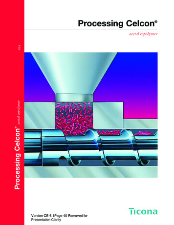
3. Fast rotation speed3. Drop the rotation speed.4. Lack of molding function4. Use molding machine with appropriate injection volume (more thantwo times bigger compare to the cavity volume).Mold releasing defect1. Lack of draft angle and polishing1a. Make the draft angle bigger.1b. Polish the mold towards mold releasing direction.2. Ejector pin placed at improper2. Increase the ejector pin and rearrange.location, lack in number and thickness3. High injection pressure and pressurekeeping3. Weaken the injection pressure and pressure keeping.4. Lack of cooling time4. Make the cooling time longer.Table 1-2 Molding defect of NOVADURAN and its countermeasures (Part 2)2. Mold Designing2.1 Point of mold designingDesigning of molded product should be done to fulfill demanded characteristics of desired product, and need toevaluate material's practical physicality, moldability, liquidity, and mold designing condition, comprehensively.Basic points of mold designing are indicated below.(1) Try not to make the thickness excessively thick, and try to keep it even, so that rapid change in thicknesswill not occur.If the molded product thickness is too thick, it will be the cause of defect like sink marks and void. Also, it willtake time to cool down and the molding cycle will be longer. When there is need to be thick for function, try tokeep it even by placing the recess. If there is unevenness or rapid change in thickness, flow marks might occurbecause it blocks the resin flow, or warpage might occur by uneven mold shrinkage ratio, or deformation ofmolded product might occur by uneven cooling speed.BadBadFairFairBadFairBadBadFairBadFairFigure 2-1 Design of thickness distribution- 11 -Fair
BadMachine directionFairMachine directionGoodMachine directionFigure 2-2 Design of thickness change(2) Try not to make the undercut.If there is undercut in molded product, problems likely to occur when releasing the mold, so as a general rule,there should be no undercut. When undercut have to be placed by necessity, make the undercut volume smallenough towards the limit strain based on material physicality, or design the mold construction not be forcedextraction by placing the slide core.Undercut volume (%) Figure 2-3 Undercut volumeφD-φdφD 100Figure 2-4 Design of undercut(3) Consider the draft angle.If the draft angle is not enough, resist when releasing the mold will be big and the molded product might deformby the ejector pin, so the draft angle should be taken as big as possible. Typical draft angle of NOVADURAN isabout 0.25 to 1 in unreinforced grade, and about 0.5 to 2 in GF reinforced grade. Following shows the pointsof the draft angle design in typical form.① Box, top form : Make the draft angle of the outside (cavity side) big to make it easy to take out. Makethe inside bit small to take balance of the cavity left and the core (outside 1 to 2 , inside 0.5 to 1 ).When placing the inverse warpage as a countermeasure against the warpage, taking the draft anglebigger is good.② Boss : Boss is relatively difficult to take out, so the draft angle need to be big (0.5 to 1 ). The basearea will be big if the boss height is high, so making a hollow is one way to prevent the sink marks.③ Grid : The pitch need to be big, because if it is small (smaller than 3mm), taking out will be difficult.- 12 -
Also, it will be more difficult to take out as the grid number increases, so the draft angle need to be bigdepending on the grid number (3 to 5 ).④ Rib : In the case of longitudinal rib, draft angle of more than 0.25 , in the case of bottom rib, draftangle of more than 0.5 is preferred. Also, from workability point of view, more than 1mm thickness forthe tip of a rib is preferred.⑤ Texture : The draft angle will differ by the texture type, depth, direction, processing method, orwhether it will be undercut or not, but generally, 4 to 5 (3 to 4 smallest) of draft angle is necessary.Figure 2-5 Design of draft angle(4) Try not to make the sharp corner.Sharp corner will block the resin flow when molding, which will become a cause of the flow marks. Also, thestress will concentrate on the sharp corner part, so it likely to be the cause of deterioration in strength such asnotch effect and residual strain. If there is metal insert, be careful so that the burr and the notch will not occuron the metal processing face.Figure 2-6 Design of corner partFigure 2-7 Corner radius and stress concentration factorFigure 2-8 Notch radius dependence property of impact strength(5) Do not make the rib too thick.If placing the recess on a specific part is difficult because of its strength, try to make the thickness even bysetting up the rib.Figure 2-9 Design of recess by rib- 13 -
(6) Do not make the ratio of diameter to length big in the case of cylindrical molded product.Long and thin core pin might cause problem such as falling over and getting broken by the resin pressure whenmolding. Also, the temperature of the central part of the core pin will become high compared to the end, so innerdiameter measurement is likely to vary, and if the mold cycle is short, skin layer of the inner diameter side mightbe torn by the resin inner pressure.Figure 2-10 Dimensional stabilize of cylindrical molded product by rib(7) Consider the weld location and the resin orientation, and determine the gate location, direction, andnumber.(8) Try to make the molded product form tough.(9) Consider the easiness of mold creation, and be careful the following points when forming so that moldmachining and finishing will be easier.① Parting line should be simple straight line without a tilt.② Round every edge, both inside and outside.③ If mold machining is difficult because of the shape, use embedded structure.④ Select a shape such as straight line and circle, so that deciding by machining will be simple.⑤ Decide surface finishing by parts, to get rid of unnecessary face accuracy.⑥ There are dimensions that directly settle by the mold and dimensions does not settle by the mold, so becareful.(Table 2-1)(10) Design considering building up and fabricating.TypeDimension that settle1. General dimensionby the moldExample of applicationAccuracy1. Inside or outside horizontal and verticalHighdimension of box type, inner and outerdiameter of the cup2. Curvature radius2. Roundness of corner part3. Central clearance3. Space of hole, salient, and recessMiddle3. Central clearance of implanted hardwareMiddleMiddleDimension that does1. Dimension at mold opening1. Outside height of box type and cup,not settle by the molddirectionthickness of base(dimensionthatgetLowacross the parting line)2. Dimension that settle by mold2. Dimension settle by relation of core andassemblagecavity, relation of side core.3. Parallelism, eccentricity3. Swing of inner and outer axis of hollowcylinder, shift of concentric circle- 14 -LowLow
Other dimension1. Skew, warpage, crook1. Making the injection speed fasterLow2. Angle2. Scale angle of indicator, tilt part angleLowTable 2-1 Dimensions settle directly by mold and dimensions does not settle by mold2.2 Gate DesigningGate selection should be made considering molded product shape, number, performance, appearance,economic efficiency, and moldability. There are many types of gates, and Figure 2-11 indicates structure of eachgate.(1) Direct sprue gateUsed in the case of single- cavity, or when placing the gate directly to the base of the molded product.Residual strain tend to occur because the injection pressure will directly apply to the molded product, but itsmold construction is most simple.(2) Side gateThis type is most generally adopted, and used well in multi-cavity mold. Its shape is rectangle or semicircle,and placed at side of the molded product.(3) Fan gateIts structure is similar to the side gate, but gate width is bigger and fan-shaped. Used in large size moldedproduct.(4) Pinpoint gateDiameter of the pinpoint gate is 0.5mm to 2mm, and as an advantage, it does not need any finishing. Gate sealis fast and pressure that generates residual strain will not apply to the molded product. If the gatecross-sectional area is small, flow distance will decrease and flow marks tend to occur around the gate.(5) Disk gateThis gate is used to prevent eccentricity and weld when molding disk or cylinder shaped one. However, thereis a disadvantage that the finishing of the gate part is difficult.(6) Ring gateUsed like the disk gate. Ring part must get filled first and then the cylinder part, otherwise the weld will occur.(7) Film gateThis type will be applied to the plate shaped molded product. This type is effective to prevent deformation bysuppressing residual strain.(8) Tab gate- 15 -
This is a method that set up a tab on the side of the molded product, and place a gate there. Normally, thegate and the tab should be placed at a right angle. Gate seal will happen on the gate part, so suppressing residualstrain and flow marks inside the tab is possible.(9) Submarine gateThere is a runner part on the parting line surface, but the gate reach the side of the molded product throughfixed template or moving template from the runner part. When releasing the mold after mold opening, the gatewill automatically get cut.2.3 Pressure lossPressure loss will occur on the sprue, runner, and gate part so be careful. Presuming the resin is Newtonianfluid, the amount of pressure loss will be shown as the following, and from that, we know it depends largely oncross-section thickness and diameter.【 Rectangle cross-section 】Pressure loss ΔP 12・L・η・QW・hη : Viscosity, Q : Current speed3L : Length,W : Width,h : thickness【 Circle, semicircle, ellipse cross-section 】Pressure loss ΔP however R 8・L・η・Qη : Viscosity, Q : Current speed4L : Length,π・R2・SR : Hydraulic radiusS : Sectional areaℓℓ : Cross-section perimeterPractically, resin is a non Newtonian fluid with viscoelasticity, so viscosity will decrease if the shearing forceget bigger and cross-section thickness and diameter get smaller. So the actual effect of pressure loss might be bitsmaller than the formula above.LandGate width (w)Gate thickness (t)GateDirect sprue gateSide gate- 16 -Fan gate
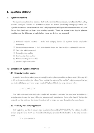
Secondary sprueProductSprueGateEjector pinMain runnerSub runnerDiskOverflowRing gateGate diameterPinpoint gateDisk gateRing gateProductParallel runnerDivision surfaceTabMain runnerSprueProductGate RunnerPrimary gatePinpoint gateDisk gateEjector pinRing gateFigure 2-11 Gate type and structure2.4 Multi-cavity layoutIn the case of multi-cavity type, runner design will play an important role, because the dimension tend to varywidely. Family-cavity type, which molds the product with different cavity shapes simultaneously, is basically notrecommended.In the case of double-cavity layout, right and left layout is preferred rather than above and bottom, because itwill be affected by the gravity. Especially talking about thick molded product, the resin will be affected by thegravity at the lower cavity, and jetting might occur because it droop down to the lower cavity after gettingthrough the gate.In the case of multi-cavity type, the runner length to each cavity should be laid out equally (isometry runner),and try to fill up simultaneously. If the runner length differs like a serial runner, keep balance by the gatediameter. In the case of more than octuple-cavity type, inner cavity tend to get filled even if the isometry runneris used, so keeping balance by the gate diameter might be necessary (Figure 2-13).- 17 -
(A) Serial runner(B) Isometry runner(C) Isometry runnerFigure 2-12 Layout example of multi-cavityInner cavity tend to get filledFigure 2-13 Filling pattern example of octuple-cavity isometry runner (one side half model)2.5 Cooling pi
1. Injection Molding 1.1 Injection machine The injection machine is a machine that melt plasticize the molding material inside the heating cylinder and inject this into the mold tool to create the molded product by solidifying inside it. The injection machine is constructed of a mold