Transcription
AutodeskSimulation Moldflow Plastics madeperfect.Plastic injection moldingsimulation of a concept consumerprinter. Designed in Autodesk Inventor software. Simulated inAutodesk Simulation Moldflow software. Rendered in Autodesk 3ds Max software.
Validation and Optimization of Plastic PartsInnovative plastic resins and functional plastic part designs areon the rise in almost every industry. Plastics and fiber-filledcomposites answer growing pressures to reduce costs and cuttime to market. The need for simulation tools that providedeep insight into the plastic injection molding process hasnever been greater.ContentsValidation and Optimizationof Plastic Parts . 1Part Layout Simulation.2Injection Molding Process Simulation. 3CAD Interoperability and Meshing . 5Results Evaluationand Productivity Tools.6Autodesk Simulation Moldflow plastic injectionmolding software, part of the Autodesk Simulationsolution for Digital Prototyping, provides toolsthat help manufacturers predict, optimize, andvalidate the design of plastic parts, injectionmolds, and extrusion dies. Companies worldwideuse Autodesk Simulation Moldflow Adviser andAutodesk Simulation Moldflow Insight softwareto help reduce the need for costly physical prototypes, reduce potential manufacturing defects, andget innovative products to market faster.Feature Comparison.71Autodesk Simulation Moldflow Product LineAutodesk is dedicated to providing a wide rangeof injection molding simulation tools to help CAEanalysts, designers, engineers, mold makers, andmolding professionals create more accurate digitalprototypes and bring better products to marketat less cost.
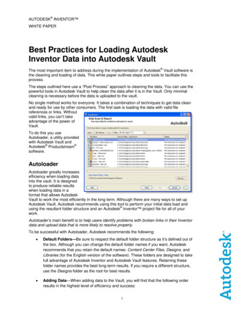
Part Layout SimulationValidate and optimize plastic parts, injection molds, resinselection, and the injection molding process.Plastic Flow SimulationSimulate the flow of melted plastic to help optimizeplastic part and injection mold designs, reducepotential part defects, and improve the moldingprocess.Part DefectsDetermine potential part defects such as weld lines,air traps, and sink marks, then rework designs tohelp avoid these problems.Thermoplastic FillingSimulate the filling phase of the thermoplasticinjection molding process to help predict the flow ofmelted plastic and fill mold cavities uniformly; avoidshort shots; and eliminate, minimize, or repositionweld lines and air traps.Feed System SimulationModel and optimize hot and cold runner systemsand gating configurations. Improve part surfaces,minimize part warpage, and reduce cycle times.Hot Runner SystemsModel hot runner system components and set upsequential valve gates to help eliminate weld linesand control the packing phase.Gate LocationIdentify up to 10 gate locations simultaneously.Minimize injection pressure and exclude specificareas when determining gate location.Thermoplastic PackingOptimize packing profiles and visualize magnitudeand distribution of volumetric shrinkage to helpminimize plastic part warpage and reduce defectssuch as sink marks.Runner Design WizardCreate feed systems based on inputs for layout,size, and type of components, such as sprues,runners, and gates.Balancing RunnersBalance runner systems of single-cavity, multicavity,and family mold layouts so parts fill simultaneously,reducing stress levels and volume of material.2
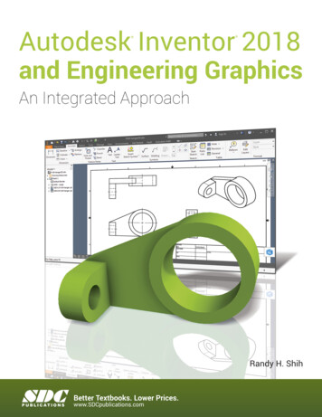
Injection Molding Process SimulationMold Cooling SimulationImprove cooling system efficiency, minimize partwarpage, achieve smooth surfaces, and reducecycle times.Cooling Component ModelingAnalyze a mold’s cooling system efficiency.Model cooling circuits, baffles, bubblers, and moldinserts and bases.Cooling System AnalysisOptimize mold and cooling circuit designs to helpachieve uniform part cooling, minimize cycletimes, reduce part warpage, and decreasemanufacturing costs.Rapid Heat Cycle MoldingSet up variable mold surface temperature profilesto maintain warmer temperatures during filling toachieve smooth surfaces; reduce temperatures inthe packing and cooling phases to help freeze partsand decrease cycle times.WarpagePredict warpage resulting from process-inducedstresses. Identify where warpage might occurand optimize part and mold design, materialchoice, and processing parameters to help controlpart deformation.Shrinkage and Warpage SimulationEvaluate plastic part and injection mold designs tohelp control shrinkage and warpage.ShrinkageMeet part tolerances by predicting part shrinkagebased on processing parameters and grade-specificmaterial data.Core Shift ControlMinimize the movement of mold cores by determining ideal processing conditions for injectionpressure, packing profile, and gate locations.Fiber Orientation and BreakageControl fiber orientation within plastics to helpreduce part shrinkage and warpage across themolded part.CAE Data ExchangeValidate and optimize plastic part designs usingtools to exchange data with mechanical simulationsoftware. CAE data exchange is available withAutodesk Simulation, ANSYS , and Abaqus software to predict the real-life behavior of plasticparts by using as-manufactured material properties.3
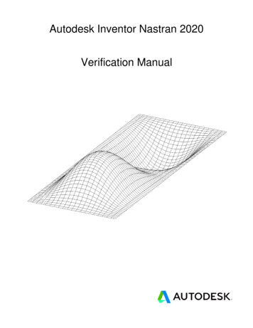
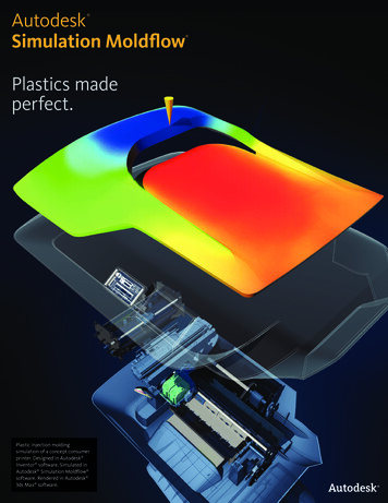
Injection Molding Process SimulationThermoset Flow SimulationSimulate thermoset injection molding, RIM/SRIM,resin transfer molding, and rubber compoundinjection molding.Reactive Injection MoldingPredict how molds will fill with or without fiberreinforced preforms. Help avoid short shots dueto pregelation of resin, and identify air traps andproblematic weld lines. Balance runner systems,select molding machine size, and evaluatethermoset materials.Specialized Simulation ToolsSolve design challenges with simulation.Specialized Molding ProcessesSimulate a wide range of plastic injection moldingprocesses and specialized process applications.Insert OvermoldingRun an insert overmolding simulation to helpdetermine the impact of mold inserts on melt flow,cooling rate, and part warpage.Gas-Assisted Injection MoldingDetermine where to position polymer and gasentrances, how much plastic to inject prior to gasinjection, and how to optimize size and placementof gas channels.Co-Injection MoldingVisualize the advancement of skin and corematerials in the cavity and view the dynamicrelationship between the two materials as fillingprogresses. Optimize material combinations whilemaximizing the product's cost-performance ratio.Microchip EncapsulationSimulate encapsulation of semiconductor chipswith reactive resins and the interconnectivity ofelectrical chips. Predict bonding wire deformationwithin the cavity and shifting of the lead frame dueto pressure imbalances.Underfill EncapsulationSimulate flip-chip encapsulation to predictmaterial flow in the cavity between the chip andthe substrate.Two-Shot Sequential OvermoldingSimulate the two-shot sequential overmoldingprocess: one part is filled; the tool opens andindexes to a new position; and a second part ismolded over the first.BirefringencePredict optical performance of an injection-moldedplastic part by evaluating refractive index changesthat result from process-induced stresses. Evaluatemultiple materials, processing conditions, andgate and runner designs to help controlbirefringence in the part.Injection-Compression MoldingSimulate simultaneous or sequential polymerinjection and mold compression. Evaluatematerial candidates, part and mold design,and processing conditions.MuCell MuCell (from Trexel, Inc.) simulation resultsinclude filling pattern, injection pressure, and cellsize. These are all critical factors in optimizinga given part for the process, as well as theprocess itself.4
CAD Interoperability and MeshingUse tools for native CAD model translation and optimization.Autodesk Simulation Moldflow provides geometry support forthin-walled parts and thick and solid applications. Select meshtype based on desired simulation accuracy and solution time.CAD Solid ModelsImport and mesh solid geometry from Parasolid based CAD systems, Autodesk Inventor software,CATIA V%, Pro/ENGINEER , Creo Elements/Pro, Autodesk Alias , Siemens NX , Rhino , andSolidWorks , as well as ACIS , IGES, and STEPuniversal files.Error Checking and RepairScan imported geometry and automatically fixdefects that can occur when translating a modelfrom CAD software.Centerline Import/ExportImport and export feed system and coolingchannel centerlines from and to CAD software, tohelp decrease modeling time and avoid runner andcooling channel modeling errors.Autodesk Simulation Moldflow CAD DoctorCheck, correct, heal, and simplify solid modelsimported from 3D CAD systems to preparefor simulation.3D SimulationsPerform 3D simulations on complex geometryusing a solid, tetrahedral, finite element meshtechnique. This approach is ideal for electricalconnectors, thick structural components, andgeometries with thickness variations.Dual Domain TechnologySimulate solid models of thin-walled parts usingDual Domain technology. Work directly from 3Dsolid CAD models, leading to easier simulation ofdesign iterations.Midplane MeshesGenerate 2D planar surface meshes with assignedthicknesses for thin-walled parts.5
Results Evaluation and Productivity ToolsVisualize and evaluate simulation results, and use automaticreporting tools to share the results with stakeholders. Takeadvantage of features such as a material database and advisersto further boost productivity.Results Interpretation and PresentationUse a wide range of tools for model visualization,results evaluation, and presentation.Material DataImprove simulation accuracy with precisematerial data.Automation and CustomizationAutomate common tasks and customize AutodeskSimulation Moldflow software for your organization.Results AdviserQuery regions of a model to identify primary causesof short shots and poor part or cooling quality. Getsuggestions on how to correct the part, mold, orprocess.Material DatabaseUse the built-in material database of gradespecific information on more than 8,500 plasticmaterials characterized for use in plastic injectionmolding simulation.API ToolsApplication programming interface (API)tools enable you to automate common tasks,customize the user interface, work with thirdparty applications, and help implement corporatestandards and best practices.Photorealistic Defect VisualizationIntegration with Autodesk Showcase softwareenhances quality assessments of plastic parts byexamining near-photorealistic renderings of digitalprototypes.Automatic Reporting ToolsUse the Report Generation wizard to create webbased reports. Prepare and share simulation resultsmore quickly and easily with customers, vendors,and team members.Microsoft Office Export CapabilityExport results and images for use in Microsoft Word reports and PowerPoint presentations.Autodesk Simulation Moldflow CommunicatorCollaborate with manufacturing personnel,procurement engineers, suppliers, and externalcustomers using Autodesk Simulation Moldflow Communicator software. Use the AutodeskSimulation Moldflow Communicator resultsviewer to export results from Autodesk SimulationMoldflow software so stakeholders can more easilyvisualize, quantify, and compare simulation results.Autodesk Simulation Moldflow Plastics LabsGet plastic material testing services, expert datafitting services, and extensive material databaseswith the Autodesk Simulation Moldflow Plastics Labs.Productivity ToolsUse advisers and extensive help to boost productivity.Cost AdviserLearn what drives part costs to help minimize thosecosts. Estimate product costs based on materialchoice, cycle time, post-molding operations, andfixed costs.Design AdviserQuickly identify areas of plastic parts that violatedesign guidelines related to the injection moldingprocess.HelpGet help on a results plot, including informationon what to look for and how to correct typicalproblems. Learn more about solver theory,interpreting simulation results, and designingbetter plastic parts and injection molds.6
Feature ComparisonCompare the features of Autodesk Simulation Moldflow products to learn how Autodesk Simulation Moldflow Adviser and Autodesk Simulation Moldflow Insightsoftware can help meet the needs of your ltimate Meshing TechnologyDual Domain3DMidplaneCAD InteroperabilityCAD Solid ModelsPartsAssembliesSimulation CapabilitiesThermoplastic FillingInsert Overmolding Two-Shot SequentialOvermolding Part DefectsGate LocationMolding WindowThermoplastic PackingRunner Balancing CoolingWarpageFiber OrientationCore Shift ControlMolding ProcessesThermoplastic Injection Molding Reactive Injection MoldingMicrochip EncapsulationUnderfill EncapsulationGas-Assisted Injection MoldingInjection-Compression MoldingCo-Injection MoldingMuCell BirefringenceDatabasesThermoplastics MaterialsThermoset MaterialsMolding MachinesCoolant MaterialsMold Materials7
iumAutodeskSimulationMoldflowInsightUltimate CAE Data ExchangeAutodesk Simulation AbaqusANSYSLS-DYNA NEi NastranSupported LanguagesEnglishChinese (Simplified)Chinese ugueseSpanish 8
Digital Prototyping for the Manufacturing MarketAutodesk is a world-leading supplier of engineering software,providing companies with tools to design, visualize, andsimulate their ideas. By putting powerful Digital Prototypingtechnology within the reach of mainstream manufacturers,Autodesk is changing the way manufacturers think about theirdesign processes, and helping them to create more productiveworkflows. The Autodesk approach to Digital Prototyping isunique in that it is scalable, attainable, and cost-effective, whichallows a broader group of manufacturers to realize the benefitswith minimal disruption to existing workflows, and provides themost straightforward path to creating and maintaining a singledigital model in a multidisciplinary engineering environment.Learn More or PurchaseAccess specialists worldwide who can provide product expertise, a deepunderstanding of your industry, and value that extends beyond your software.To license Autodesk Simulation Moldflow software, contact an AutodeskAuthorized Reseller. Locate a reseller near you at www.autodesk.com/reseller.To learn more about Autodesk Simulation Moldflow software, visitwww.autodesk.com/moldflow.Autodesk EducationFrom instructor-led or self-paced classes to online training or educationresources, Autodesk offers learning solutions to fit your needs. Gain accessto free* software if you are a student or educator. Get expert guidance atan Autodesk Authorized Training Center (ATC ) site, access learning toolsonline or at your local bookstore, and validate your experience with AutodeskCertification. Learn more at www.autodesk.com/learning.Autodesk SubscriptionAutodesk Subscription allows customers to extend the value of their softwareinvestment with access to the latest releases, powerful web services, andexpedited technical support. Learn more at www.autodesk.com/subscription.*Free products are subject to the terms and conditions of the end-user license agreement that accompaniesdownload of this software.Autodesk, Alias, ATC, Autodesk Inventor, Inventor, Moldflow, Showcase, and 3ds Max are registered trademarksor trademarks of Autodesk, Inc., and/or its subsidiaries and/or affiliates in the USA and/or other countries. Allother brand names, product names, or trademarks belong to their respective holders. Autodesk reserves theright to alter product and services offerings, and specifications and pricing at any time without notice, and isnot responsible for typographical or graphical errors that may appear in this document. 2012 Autodesk, Inc.All rights reserved.
process itself. Specialized Molding Processes Simulate a wide range of plastic injection molding processes and specialized process applications. Gas-Assisted Injection Molding Determine where to position polymer and gas entrances, how much plastic to inject prior to gas injection