Transcription
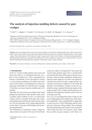
eXPRESS Polymer Letters Vol.9, No.4 (2015) 394–400Available online at www.expresspolymlett.comDOI: 10.3144/expresspolymlett.2015.37The analysis of injection molding defects caused by gatevestigesT. Tábi1,2, A. Suplicz1, F. Szabó1, N. K. Kovács1, B. Zink1, H. Hargitai3, J. G. Kovács1*1Department of Polymer Engineering, Faculty of Mechanical Engineering, Budapest University of Technology andEconomics, M!egyetem rkp. 3., H-1111 Budapest, Hungary2MTA–BME Research Group for Composite Science and Technology, M!egyetem rkp. 3., H-1111 Budapest, Hungary3Department of Materials Science and Technology, Széchenyi István University, Egyetem tér 1., H-9026 Gy"r,HungaryReceived 26 August 2014; accepted in revised form 2 November 2014Abstract. Issues of product safety are the most serious problems of an injection molded product due to their risk to humanhealth. Such a safety problem can be the needle-shaped vestige at the gate zone of injection molded products, called a gatevestige. Only observations of the formation of gate vestiges can be found in the literature, but the processing parametersinfluencing their dimensions, especially their height have not been studied yet. Our goal was to study the effect of variousinjection molding processing parameters and gate constructions on gate vestige formation.Keywords: processing technologies, injection molding defect, damage mechanism, gate vestiges, 3-plate mold1. IntroductionIn the 21st century modern plastics have more andmore roles and are so widespread that they are apart of our everyday lives. Their consumption hasbecome a benchmark of how developed a countryis. In the injection molding cycle defects can occur,such as burn marks [1], delamination [2], flash [3],jetting [4], sink marks [5], weld lines [6] or warpage[7] and these can cause injection molded parts to berejected.Typically, the most serious are problems that coulddamage the mold and/or affect product safety. Sucha product safety problem can be a so-called gatevestige, which is a remnant of the gate, thus a separation phenomenon between the runner and the product. The size and shape of the vestige depend mostlyon the shape of the gate (mold design) and the processing parameters.The elimination or moderation of gate vestiges byusing various valve gates in the case of a hot runnersystem are widely investigated [8]. Valve gates likereciprocating pinpoint gates have a mechanicallyactivated pin that shuts off the gate as the pin movesforward, which provides mechanical sealing and arelatively clean vestige [9, 10]. These valve gates provide the most control over gate vestiges but they significantly increase the complexity of the mold andintroduce wear problems. Vestiges can also be controlled by using a standard fixed hot tip torpedo in hotrunner systems. Gate vestiges and freezing are controlled by the temperature and the location of the tipin the gate area [10].Xie et al. [11] investigated the effect of gates on thecavity filling pattern and residual stress of the injection molded part. They concluded that if a larger gateis used, the cavity will be filled faster and the residual stress of the part will be smaller. They concludedthat melt temperature and injection rate can significantly affect the above two aspects, which mighthave an effect on gate vestiges as well. Shen et al.*Corresponding author, e-mail: kovacs@pt.bme.hu BME-PT394
Tábi et al. – eXPRESS Polymer Letters Vol.9, No.4 (2015) 394–400[12] showed simulation methods for gate locationanalysis, in which they calculated the ideal locationand size of gates. Zhai et al. [13] performed gate location optimization for injection molding. They concluded that if injection pressure at the end of fill isminimized, gate location can be optimized. In spiteof the best location, possible injection moldingdefects were not mentioned by the authors.Sánchez and Lladó [14, 15] investigated direct gates,which are similar to pinpoint gates but significantlylarger, thus the conclusions cannot be used for thosebecause of the significantly different shear effects.For cold runner systems like three-plate molds, gatevestige and other injection molding defects can beavoided or minimized if a suitable gate or nozzledesign is used. The tapered region should be as shortas possible to achieve lower pressure for filling andreduce the height of the vestige. Generally, its lengthranges from 0.13 to 0.25 mm. A tapered region andsharp corners at the entry into the cavity are important to ensure that the plastic will break between thegate and the product but as near the product as possible, leaving no or only a little vestige. It is important to optimize gate size as it has a major influenceon gate vestige, shear induced heat, holding time andother important parameters. The gates of a threeplate mold are inherently self-degating, since thegate breaks off as the product is ejected from thecavity [9].Although the problem of gate vestiges seems to besolved in expensive and complicated hot runnermolds, in three-plate molds gate vestiges can stilloccur. The height of gate vestiges is determined notonly by the mechanical strength of the solidified thermoplastic, but as gate vestiges are formed as a resultof a complex process, injection molding parametersprobably also have a significant effect on it. Noinformation was found in the literature on the effectof injection molding parameters on the formation ofgate vestiges.In this paper our goal was to investigate the effectof various injection molding processing parametersand examine various gate constructions influencingthe formation of gate vestiges. A quick measuringmethod was also developed to determine the dimensions of gate vestiges without any need for timeconsuming optical and/or scanning electron microscope measurements.2. Materials and equipmentsBASF Terluran GP35 injection molding grade ABSterpolymer was chosen for the tests. This grade ofABS has a specific gravity of 1.04 g/cm3, a melt volume rate of 34 cm3/10 min (at 220 C and 10 kg ofload) and a recommended melt and mold temperature of 220–270 C and 40–60 C respectively. Thematerial was dried at 85 C for 4 hours prior to injection molding.A three-plate mold with 16 cavities was chosen forthe examinations. In the mold there were big differences between gate dimensions, therefore 15 cavities were blocked and the mold was used as a singlecavity mold. The effect of nozzle (gate) geometry ongate vestiges was also measured. Some geometricalparameters such as the diameter of the outlet, thenozzle end height and the internal angle near theoutlet were varied in our experiments (Figure 1).The other main geometrical parameters includingthe 2 mm inner diameter, the 15.6 mm length of thenozzle and the interior draft angle of 2 were thesame. The varied geometrical parameters of the various nozzles can be seen in Table 1.An Engel Victory 330/60 injection molding machinewith a clamping force of 600 kN was used for producing parts for the investigation. The injection molding machine had a 35 mm diameter screw capable ofa maximum injection rate of 151 cm3/s and a maximum injection pressure of 1595 bars. The specimenswere injection molded with the following parameters using pressure controlled filling (Table 2).Figure 1. The varied geometrical parameters of the nozzles395
Tábi et al. – eXPRESS Polymer Letters Vol.9, No.4 (2015) 394–400Table 1. Geometrical parameters of various nozzle 1.01.01.21.21.21.01.0Nozzle end e[ ]4545454545454545453060Table 2. Injection molding set-up parametersInjection molding parameterValueTotal injection time (the sum of the filling and holding2.5time) [s]Pressure [bar]600Injection rate limit [cm3/s]110Residual cooling time [s]5Screw rotational speed [m/min]17.1Back pressure [bar]100Temperature of the zones [ C]238–200Temperature of the stationary/movable mold half [ C] 35/16Cycle time [s]11.2Injection molded specimens produced in the first50 cycles were automatically rejected. Then, whensteady-state production conditions were reached,injection molding was continued and every tenthspecimen (cycle) was selected for measurement. Atotal number of twelve specimens were selectedfrom continuous production to determine the average and the standard deviation of the measured values.Mold temperature was set up based on preliminarystudies and the inlet temperatures were chosen tomaintain a uniform mold surface temperature. Someinjection molding parameters (cooling time, moldopening speed, injection rate and total injection time)were varied to better understand gate vestige formation and to map their effect on the dimensions of thegate vestiges.Microscopic measurements were performed toobserve gate vestiges by using an Olympus BX 51Mtype optical microscope and a Jeol JSM 6380LA typeelectron microscope. The optical microscope wasused only to determine the geometry of the gate vestiges, while the scanning electron microscope (SEM)was used for deeper analysis to determine the causesof gate vestige formation. To speed up the measurement of dimensions and at the same time keep theaccuracy of the optical microscope, a UniversalSerial Bus (USB) microscope type Celestron Handheld Digital Microscope was used in a combinationwith and self-developed software to automaticallyidentify gate vestige dimensions. The new systemwas previously tested and validated by the conventional optical microscopic measurements.3. Measurement methodAs the first step, the optical microscope was used todetermine the dimensions of gate vestiges, namelytheir height, bottom (base) diameter, and top diameter. By using 50# magnification, the gate sections ofthe specimens were easily observable and the dimensions of the gate vestiges were measured (Figure 2).The standard deviation of measurement was foundto be low when the same 12 specimens were measured by various operators (human factor) and alsothe repeatability of the measurements was found tobe excellent. The maximum differences betweenthe values measured by the three measuring personswere 48, 31 and 17 µm, (height, bottom and topdiameter). The USB microscope was also tested;photos were taken, loaded into graphics softwareand the dimensions of the gate vestiges were determined by converting the dimensions in pixels intoµm using the resolution of the image. There is nosignificant difference between the measured valuesobtained from the optical and the USB microscope.It can be stated that the USB microscope not onlyallows faster evaluation but is also at least as accurate as the optical microscope, which makes theUSB microscope suitable for the measurements.Figure 2. Analyzing the dimensions of gate vestige396
Tábi et al. – eXPRESS Polymer Letters Vol.9, No.4 (2015) 394–4004. Results and discussion4.1. The effect of nozzle geometry on gatevestigesBefore analyzing the effect of various nozzle geometries, the reproducibility of the dimensions of gatevestiges was checked. Reproducibility was found tobe very good. Injection molding was performed usingdifferent geometry nozzles. Figure 3 shows the mostimportant dimension, the height of the gate vestigesaccording to the various nozzle geometries.It can be seen that the height of gate vestiges can besignificantly decreased by modifying the geometryof the nozzle. According to the height of the gatevestige, various types can be observed, such as lowFigure 3. The height of the gate vestiges according to thevarious nozzles(nozzles number 1 and 2), medium (nozzles number 3, 6 and 7) and high (nozzles number 4, 5, 8, 10and 11) and even no gate vestige in the case of nozzle number 9. Nozzles number 9, 1, 3, and 5 werechosen to represent no (zero), low, medium and highgate vestiges, respectively, for SEM observation andthe images of the gate vestiges were also insertedinto the drawings of the nozzles for visualization(Figure 4).It is obvious that nozzle number 9 was preferred asno gate vestige was produced and surprisingly, thehighest gate vestige was not created with the nozzlewith the largest nozzle end height dimension. It canalso be seen that the diameter of the vestige is notequal to the diameter of the nozzle, thus the vestigedoes not form by the material simply detachingfrom the inner wall of the nozzle, but it is torn fromits own material. This explains why a highly shearedregion of material was found on the surface of thevestiges, which probably formed during degating dueto the friction within the material or due to the highshear during the filling phase (Figure 5). This wouldmean that gate vestige takes place only as delamination at the interface of highly oriented layers. TheseFigure 4. SEM micrographs and 10 superimposed microscopic pictures of the gate vestiges and the nozzle geometries forno (zero) gate vestige/nozzle number 9. (a), low (broken) gate vestige/nozzle number 1. (b), medium (broken)gate vestige/nozzle number 3. (c) and high (theoretically ‘good’) gate vestige/nozzle number 5. (d)Figure 5. The highly sheared region of the gate vestige397
Tábi et al. – eXPRESS Polymer Letters Vol.9, No.4 (2015) 394–4004.2. The effect of injection moldingparametersIn this chapter the effect of injection molding parameters, such as cooling time, mold opening speed,injection rate and total injection time on the dimension of gate vestiges were investigated. For furtherexperiments, nozzle number 9 was used.Figure 6. Gate vestige height produced with various nozzles as a function of nozzle end heightkind of delamination was observable on all gatevestige surfaces.It is assumed that the height of gate vestiges is limited because if the gate vestige forming during filling the cavity was too high, it would break duringdegating due to the long grip length and this wouldresult in a shorter and broken gate vestige. The heightof the gate vestige can be seen as a function of nozzle end height and nozzle diameter in Figure 6.The results seem to be stochastic at first sight, but ifit is taken into account that some of them are broken, and some of them are undamaged, just pulledout from the inner core, a clearer tendency can beobserved. No significant difference was found in thebottom diameter of gate vestiges as nozzle end heightwas increased, but there is a positive correlationbetween gate vestige bottom diameter and nozzleoutlet diameter. As expected, when the outlet diameter of the nozzle was increased, the bottom diameter of gate vestiges increased (Figure 7). In the caseof nozzle number 9 (1.2 mm nozzle diameter and0.8 mm nozzle end height) no gate vestige exists thusonly the outer diameter of the remaining ‘ring’ (Figure 4a) could be measured by SEM. Changing theinternal angle near the outlet of the nozzles did nothave a significant effect on the dimensions of gatevestiges.Figure 7. Gate vestige diameter at the bottom as a function ofnozzle diameter, produced with various nozzles4.2.1. Analysis of cooling timeGate vestiges may be caused by the breaking of thestill hot and thus rubber-like runner system. In orderto analyze this possibility, specimens were injectionmolded with an extremely long cooling time of10 minutes. It was found that the height of the gatevestige did not change significantly; only a negligible decrease was found. It means that gate vestigesdo not form because of the breaking of a still warmrunner system, but form previously in the fillingand holding phases.4.2.2. Analysis of mold opening speedSince the mechanical properties of polymers dependon the rate of deformation, the effect of mold opening speed was investigated to find whether it is possible to tear the specimens from the runner systemleaving no gate vestige by using extremely high orlow mold opening speeds. The original value of moldopening speed of 150 mm/s was used as a reference,while 10 and 450 mm/s of mold opening speeds wereinvestigated as the smallest and highest possiblespeeds. The results showed that mold opening speedhas only a minor effect on the height of gate vestiges. A possible explanation of the results is that itwas not possible to vary deformation rate by moldopening speed at the desired level, where it couldhave had a significant effect on the gate vestige;only the top of the vestige was broken.4.2.3. Analysis of injection rateThe effect of injection rate, or screw (ram) speed ongate vestiges was also analyzed. For this test 15, 20,30, 40 and 50 cm3/s were set for injection rates. It wasfound that by decreasing the injection rate, the heightof the gate vestige also decreased (Figure 8).By increasing the injection rate, the bottom diameter of gate vestiges remains constant, while theirheight increases and their top diameter decreases,which means that they get more and more tapered.A possible explanation of the decreasing height of398
Tábi et al. – eXPRESS Polymer Letters Vol.9, No.4 (2015) 394–400appeared. This most preferred ‘no gate vestige’ interval was only stable when total injection time wasbetween 2.3 and 2.8 s. This special phenomenon isto be further investigated so that this kind of gatevestige can be reproduced on other products. Thefact that the size of gate vestiges decreased as thetotal injection time was increased can be explainedby the longer holding phase within the total injection time.Figure 8. Dimensions of the gate vestige as a function ofinjection rategate vestiges is the lower melt rate during the fillingof the cavity, which results in less shearing.4.2.4. Analysis of total injection time(filling holding)The effect of total injection time on the formation ofgate vestiges was also investigated. The original valueof total injection time (2.5 s) was varied between 2and 5 s, while cooling time was also changed tokeep the same cycle time. Since total injection timecan be divided into filling time and holding time, iftotal injection time is changed, the parameter that isactually changed is holding time. As total injectiontime was increased, the height of the gate vestigegradually decreased (Figure 9).There is a noticeable tendency that if the total injection time is increased, the height of the gate vestigedecreases. However, a special phenomenon can alsobe observed: when the total injection time is around2.5 s, no gate vestige, while at a total injection timeof 2 or 3 s, a gate vestige with a certain heightFigure 9. The height of gate vestiges as a function of totalinjection time. (For every single point 10 measurements were made where ‘Maximum’ is thehighest measured value and ‘Average’ is the average of the ten samples.)5. ConclusionsIn our work, the product safety problem of injectionmolded parts called gate vestige was investigatedwith a three-plate multi-cavity mold. Since the unbalanced runner system strongly influences the results,15 cavities were blocked. As the first step, we developed a quick measuring method suitable for accurately determining the dimensions of gate vestigeswith the help of a USB microscope. 11 different nozzles were produced to examine the effect of nozzlegeometry. The reproducibility of the technology withthe single-cavity mold was checked and found to beexcellent. It was demonstrated that by increasingnozzle end height and/or the outlet diameter of thenozzle, the height of the gate vestige could bedecreased.The effect of some of the process parameters liketotal injection time, cooling time, injection rate andmold opening speed were also tested. It was provedthat by increasing total injection time or decreasingthe injection rate, it is possible to decrease the heightof gate vestiges, while cooling time and mold opening speed had only a minor effect on their height.The main causes of gate vestiges were found to beshear and orientation conditions during molding. Itis assumed that the formation of the gate vestigestructure itself is already completed during fillingand can be found within the nozzle in the solidifiedpolymer, however, degating can still modify thisstructure by breaking it at a certain cross-section.Finally, the low standard deviation of the height ofgate vestiges proved that the whole process of gatevestige formation is not stochastic or random. Thisproves that if all the parameters and conditions ofthe injection molding process are known, the heightof gate vestiges can be calculated, although probably in a very complex way.399
Tábi et al. – eXPRESS Polymer Letters Vol.9, No.4 (2015) 394–400Acknowledgements[5] Mathivanan D., Parthasarathy N. S.: Prediction of sinkdepths using nonlinear modeling of injection moldingvariables. The International Journal of Advanced Manufacturing Technology, 43, 654–663 (2009).DOI: 10.1007/s00170-008-1749-1[6] Kovács J. G., Sikló B.: Experimental validation ofsimulated weld line formation in injection mouldedparts. Polymer Testing, 29, 910–914 (2010).DOI: 10.1016/j.polymertesting.2010.06.003[7] Kovács J. G., Sikló B.: Investigation of cooling effectat corners in injection molding. International Communications in Heat and Mass Transfer, 38, 1330–1334(2011).DOI: 10.1016/j.icheatmasstransfer.2011.08.007[8] Beaumont J. P.: Runner and gating design handbook.Hanser, Munich (2004).[9] Rees H.: Mold engineering. Hanser, Munich (2002).[10] Campo E. A.: The complete part design handbook.Hanser, Munich (2006).[11] Xie P., Guo F., Jiao Z., Ding Y., Yang W.: Effect of gatesize on the melt filling behavior and residual stress ofinjection molded parts. Materials and Design, 53, 366–372 (2014).DOI: 10.1016/j.matdes.2013.06.071[12] Shen Y-K., Wu C-W., Yu Y-F., Chung H-W.: Analysisfor optimal gate design of thin-walled injection molding.International Communications in Heat and Mass Transfer, 35, 728–734 (2008).DOI: 10.1016/j.icheatmasstransfer.2008.01.014[13] Zhai M., Lam Y. C., Au C. K., Liu D. S.: Automatedselection of gate location for plastic injection moldingprocessing. Polymer-Plastics Technology and Engineering, 44, 229–242 (2005).DOI: 10.1081/PTE-200048523[14] Sánchez B., Lladó J.: Surface quality of PVC fittingsbased on the design of the sprue. Journal of MaterialsProcessing Technology, 207, 13–20 (2008).DOI: 10.1016/j.jmatprotec.2008.04.041[15] Lladó J., Sánchez B.: Influence of injection parameterson the formation of blush in injection moulding of PVC.Journal of Materials Processing Technology, 204, 1–7(2008).DOI: 10.1016/j.jmatprotec.2007.12.063This paper was supported by the János Bolyai ResearchScholarship of the Hungarian Academy of Sciences. Thiswork was supported by the Hungarian Scientific ResearchFund (OTKA K105257 and OTKA PD 105995).This work is connected to the scientific program of the‘Development of quality oriented and harmonized R D Istrategy and functional model at BME’ project. This projectis supported by the New Széchenyi Plan (Project ID:TÁMOP-4.2.1/B-09/1/KMR-2010-0002).The work reported in this paper has been developed in theframework of the project ‘Talent care and cultivation in thescientific workshops of BME’ project. This project is supported by the grant TÁMOP - 4.2.2.B-10/1-2010-0009.The research work presented in this paper was carried out aspart of the TÁMOP-4.2.2.A-11/1/KONV-2012-0029 projectin the framework of the New Széchenyi Plan. The realization of this project is supported by the European Union, andco-financed by the European Social Fund.References[1] Garcia J. L., Koelling K. W., Xu G., Summers J. W.:PVC degradation during injection molding: Experimental evaluation. Journal of Vinyl and Additive Technology, 10, 17–40 (2004).DOI: 10.1002/vnl.20004[2] Karger-Kocsis J., Csikai I.: Skin-core morphology andfailure of injection-molded specimens of impact-modified polypropylene blends. Polymer Engineering andScience, 27, 241–253 (1987).DOI: 10.1002/pen.760270403[3] Zhu J., Chen J. C.: Fuzzy neural network-based inprocess mixed material-caused flash prediction (FNNIPMFP) in injection molding operations. The International Journal of Advanced Manufacturing Technology, 29, 308–316 (2006).DOI: 10.1007/s00170-005-2528-x[4] Oda K., White J. L., Clark E. S.: Jetting phenomena ininjection mold filling. Polymer Engineering and Science, 16, 585–592 (1976).DOI: 10.1002/pen.760160811400
An Engel Victory 330/60 injection molding machine with a clamping force of 600 kN was used for pro-ducing parts for the investigation. The injection mold - ing machine had a 35 mm diameter screw capable of a maximum injection rate of 151cm3/s and a maxi-mum injection pressure of 1595 bars. The specimens were injection molded with the following .