Transcription
CONTENTS1. Injection Molding Machine1.1 Injection Unit1.2 Clamping Unit1.3 Multi-program Control1.4 Defective Molding, Causes and Remedies2. Molding Operation2.1 Preliminary drying of materials ・Dryer2.2 Molding Conditions2.3 Other cautions2.4 Product Quality Control2.5 Material replacement ・Interruption of Operation ・Cleaning by Dismantling3. Product Design and Mold Design3.1 Product Design3.2 Mold Design4. Mold Shrinkage and Dimensional Accuracy5. CAE6. Hot Runner Molding7. Reuse of Iupilon / NOVAREX8. Annealing Treatment of Iupilon / NOVAREX8.1 Annealing Treatment8.2 Annealing Effect of using both hot air / far infrared radiation heating systemInternational System of Units (SI units)
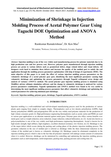
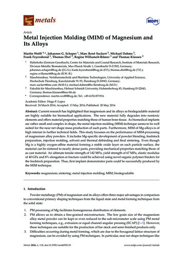
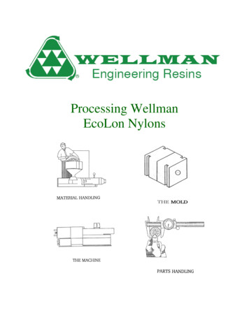
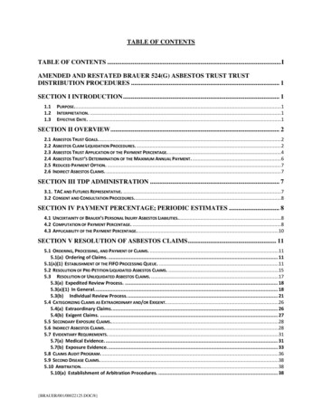
1. Injection molding machineAs for the injection molding machine, several types such as plunger type, plunger preplasticating type, screwpreplasticating type and in-line screw type, etc. have been developed so far, but presently the in-line screw type injectionmolding machine as shown in Figure 1・1-1 has become the main type.movingplateheated cylinderfixed platehopperinjection cylinderband heatermoldscrewFigure 1・ 1‐ 1 Theory of the in-line screw type injection molding machineThe injection molding machine consists of the injection unit and the clamping unit, and their features are describedbelow.1・1 Injection unit1) Injection capacityThe proper injection capacity is found from the relationship of the molding machine capacity for the weight of 1 shotas shown in Figure 1・1-2. It is necessary to select the molding machine that satisfies the capacity of the shaded area.This figure is the summary of the actual molding results in the past, but basically, it is based on the following idea.injection moldingmachine capacitygood moldingareainsufficientcapacity areaexcessivecapacity areaFig.1 shot weight (g)1・1-2 Selection of molding machine from the injection capacity
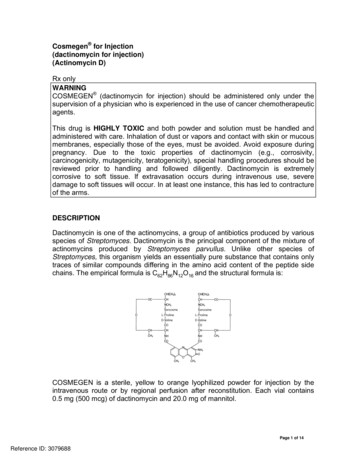
At the side where the capacity is small, plasticizing time and injection time become long, and it is used at the narrowcapacity of the molding machine. That is, the filling shortage is caused due to the extension of molding cycle and slowfilling rate.On the other hand, at the side where the capacity is large, dwell time of the resin inside the cylinder becomes long,and the resin thermally decomposes. The capacity range in the figure is indicated rather widely, but when it is easy tobe thermally decomposed with materials containing lots of pigments and additives, it is better to conduct the moldingat shot weight of 70 80% of the injection capacity.2) BarrelGenerally, using the material (for example, nitride steel etc.) for the molding of Iupilon / NOVAREX is good. However,concerning the molding of glass fiber reinforced grade (Iupilon GS etc.) and optical grade (Iupilon H-400 etc.), it isgood to consider the following for the barrel material.As for glass fiber reinforced PC, it is good to use the bimetal (double-structure cylinder covered the inside with anothermetal and centrifugal casting) to prevent the barrel abrasion. For example, the H alloy (Hitachi Metals Ltd.), N alloy(Japan Steel Works Ltd.), K alloy (Kobe Steel Ltd.) etc. are well known.Figure 1・1-3 indicates the abrasion data when molding glass fiber (30%) PC in case of using the H alloy barrel. Theabrasion of the metering section vicinity where the feed section and the backflow prevention ring contact with isimproved 1).In addition, the bimetal cylinder such as H alloy is also effective in suppressing the generation of the burn of Iupilon /NOVAREX although the burn mark and black specks due to thermal decomposition become problems in thetransparent use.1)Hitachi Metals Ltd. “H alloy” cataloguehoppercylindermolding resinnitrided steel cylinder after6-month use(disposed after measuring)variation ofinner diameterH-503 cylinder after 1 anda half year use slongitudinalheatexpansioncoefficient( )distance from the cylinder tip (mm)Fig. 1・1-3 Barrel material and abrasion data when using GF (30%) PCanti-wear, anti-corrosion
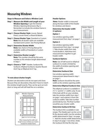
3) ScrewThe 3-stage type screw of the single flight is usually used.The screw design consists of the basic design based on the premises of smooth conveyance of pellet, plasticization formelting, dearation and compression, and measurement with a little unevenness.Supply (feed section): Stroke is designed long for conveying and melting the pellet, and increasing plasticizationquantity.Compression (compression section): Return the air and water involved in the feed section to the hopper side anddeaerate. In addition, a sufficiently melting mechanism is required. Because PC is a high viscosity material, the rapidcompression type is unsuitable and moderating compression type with gradually increasing outside diameter isrecommended.Measurement (metering section): In order to suppress the measurement unevenness, the measurementstroke is designed long, 4D 5D or more.The screw design of PC is indicated in Fig. 1・1-4. 2)screw headbackflow prevention ring pitchsealingheadmetering sectionouterdiametercompression sectionNotes: % in (feed section) shows an example of total length LBasic shape of screwstrokemetering zonecompressionzonefeed zonescrew lengthScrew diameter(mm)306090120120Screw depthFeed sectionMetering ��012.04.8Max. 14.0Max.5.6Compression ratio2.0:12.2:12.4:12.5:1Max. 3.0:1Screw pitchH 1.0D Screw diameter more than 80mmH 0.9D Screw diameter less than 80mmFig.1・1-4Design of screw for ---------------------------------2) Jonathan M. Newcome:SPE Tech Pap Reg Tech Conf. PIONEER VALLEY SEC (’77 june 8/9) 45 – 78
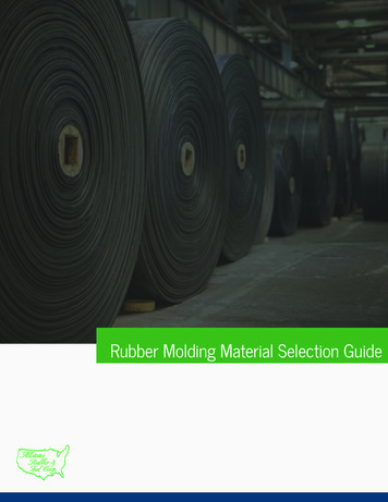
In the same figure, L/D is 20, the ratio of Feed (F) / Compression (C) / Metering (M) is divided into 60/20/20, pitch His almost equal to screw diameter D, and compression ratio C.R. of the screw is 2.0:1 2.5:1.The screw that its surface is covered with thick film hard Cr coating is good. When the glass fiber reinforced materialis used, there is a problem of abrasion, but constantly preparing spare screw and regularly exchanging after recoatingare recommended.The screw that processed nitriding treatment is hard to be worn due to its high hardness. On the other hand, fortransparent product and colored product (except the black) avoiding the burn, because it is easy to cause the burn in PCmolding, it had better use the screw that processed with (Ni Cr), (Co Cr), TiC treatment at the surface though it is alittle expensive.Recently, the example which uses dulmage, sub flight, pin screw mounted at the screw head with the purpose toimprove the melting and mixing and the dispersibility is observed with the precondition of not giving excessiveshearing force to PC and the design without PC stagnation.4) Backflow prevention valve, check ringThe screw head is equipped with the backflow prevention valve to maintain the effective injection pressure bypreventing a part of measured resin from backflow through the ditch of the screw at the time of injection. The structureof this valve is indicated in Fig. 1・1-5. It can be understood that it is easy for resin stagnation with this valvestructure.Therefore, the design of the flow path without dead space by taking enough R so as not to provide the corner as muchas possible is expected. In addition, as for high viscosity material such as PC, because torque is big, the fatigue failureoccurs in the screw of small aperture when receiving the load by repeated rotation, the use of screw of wide aperture isrecommended.Back flow ring type equipped with nailcross-section drawingFig.1・1-5Design of Shut Off Valve
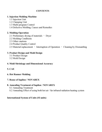
As for compound reinforced PC such as glass fiber reinforced material etc. the backflow prevention ring sometimescracks when the load becomes large compared with the non-reinforced material. When molding without being aware ofthis, the uneven dimension and the deviation from tolerance in the molding of a precise part occur due to the unstablemeasurement. It is necessary to note that such a trouble easily occurs in case of overload and insufficient purge.5) NozzleA nozzle with the structure without PC stagnation is desirable as possible. Therefore, it is necessary to avoid using theneedle shut off nozzle and torpedo nozzle due to resin stagnation. The open nozzle is the best for use.The open nozzle is easy to cause drooling, stringiness, and it is difficult to prevent them but using a long-extended nozzleand adjusting independently the temperature at two separate places of the tip and the bottom, are effective.6) HeaterSince PC is molded at high temperature, the heater with heat capacity can be heated to about 370 is used, and aband heater is usually used.When disassembling to clean the nozzle and cylinder head and when the heater is stuck with drooling resin, the heateris disconnected. It is necessary to note that it is easy to cause the burn when continuing molding without being aware ofheater disconnection.1・2 Clamping unitAs for the molding of Iupilon / NOVAREX, either the hydraulic type or the toggle type is available.Since the average value of the mold internal pressure in the molding of Iupilon / NOVAREX is 350-500kg/cm2, theclamping force F can be calculated by the following equation.F(ton) (0.35 0.50) Swhere S: projected area as indicated in Fig. 1・2-1. However, it is necessary to note that whenthe arrangement of molding is eccentric from the center of mold (center of die plate), the clamping force,which is higher than the above formula is required.clampingpressure ofthe moldingmachine(ton)projected area of the molded pieceFig.1・2-1 Selection of molding machine from clamping pressure
1・3Multistep program controlThe improvement of poor appearance of the moldings, the reduction of size unevenness betweenthe molding shots, and the measures against sink marks, warpage and flash can be achieved by controlling the injectionrate, holding pressure, screw rotation speed and back pressure with multistep program control at the time of injection.The effect of multistep program control in PC and its control system are indicated in Fig. 1・3-1. The outline isintroduced below. 3)Table 1・3-1Effect of multistep control (in case of PC)Molding conditionsInjection rateEffectPrevention of jetting mark at gate part, prevention of flowmark of sharp corner, prevention of core falling andprevention of flashHolding pressureScrew rotationspeedBack pressureReduction of molding stress and prevention of sink markStability of measurementStability of measurement3: Screw position detector5: Injection rate detector10: Screw rotation speeddetector1: Servo valve6: Injectionrate controller9: Holdingpressurecontroller7: Pressure detector2: Servo valve4: Programsetting device8: Screw back11: Screwpressurerotation omparison controllerSetting valueControllerControlledobjectControl variableDetecting valueDetectorFig. 1・3-1Outline of multistep program control system
〈 Control of the injection rate〉Since the poor appearance is resulted from the change of rate of the flow front, the measures can be done by controllingthe injection rate. The relationship between the flow rate and the defective phenomena is summarized in Table 1・3-2. Itcan be understood that the injection rate should be set to an appropriate range because there is a problem even if the flowrate is too fast or too slow.Table 1・3-2Flow rate and defective phenomenaDefective phenomena results from too Defective phenomena results from tooslowfastflow rate of resinflow rate of resinFlow markJetting markTranscription defect of moldGas burnsurfaceSink mark due to trouble ofWeld lineair purgeShort shotFig. 1 3-2 indicates an example of a measure to avoid the area of various defective phenomena by controlling theinjection rate with multistep program control.It is understood that the setting range of the injection rate to have a product of good quality is narrow (shaded part) incase of general molding.jettinggas burninjection ratearea to obtain goodproduct when settingprogram of injectionratearea to obtain goodproduct when notsetting program ofinjection ratescrew strokeweld lineFig.1・3-2gateflow marktranscriptiondefect of moldsurfaceDefective area of injection rate〈 Control of the holding pressure〉The defective phenomena such as sink marks, warpage and flash are related to the holding pressure.The measure against these phenomena becomes possible by controlling the holding pressure.The relationship between the defective phenomena such as sink marks, warpage and flash and the holding pressure issummarized in Table 1・3-3. Figure 1・3-3 indicates the pattern of the holding pressure program which was obtained toavoid the defective phenomenon ------------------------------3)Sumitomo Heavy Industries, Ltd. Plastic Machinery, lecture textbook of injection molding “Molding B Course Practical Application”
Table1.3-3Holding pressure and defective phenomenaDefective phenomena results from toolowholding pressureShort shotDefective phenomena results from toohighholding pressureFlashSink markOverdimensionUnderdimensionCrackMold release defectShrinkage strainResidual stresswarpageflashholdingpressuresink markholding pressure timeFig. 1・3-3 Holding pressure pattern to avoid defective area〈 Control of screw back pressure and screw rotation speed〉The stability of measurement (plasticization) is related to screw back pressure and screw rotation speed.It is possible to improve the accuracy of uneven repeated measurement by controlling these factors.Fig. 1・3-4 indicates the result of comparing the effects of the multistep program control of screw back pressure andscrew rotation speed about the measurement position or mold release resistance4).From this figure, it is thought that the unevenness of the measurement position, mold re
1. Injection molding machine As for the injection molding machine, several types such as plunger type, plunger preplasticating type, screw preplasticating type and in-line screw type, etc. have been developed so far, but presently the in-line screw type injection molding machine as shown in Figure 1・1-1 has become the main type.