Transcription
OVERMOLDING GUIDEGLS TPEInjection Molded Guide 1
IntroductionTable of ContentsIntroduction1Overmolding2Material Selection4Part and Mold Design6Material Handling and Preparation17TPE Injection Molding18Overmolding Processing – Maximizing Adhesion21TPE Injection Molding Troubleshooting23TPE Overmolding Troubleshooting28Index30Avient is the recognized leader in the overmolding of thermoplasticelastomers (TPEs). Our GLS overmold TPEs have excellent adhesion to a widevariety of substrates, from polyolefins, such as polypropylene and polyethylene, toengineering resins, such as PC, ABS, acetal and nylon.Avient has developed several innovative technologies that have continued toset the standard in overmolding. Our overmolding product line includes a varietyof TPE technologies designed to deliver optimum adhesion to many engineeringplastics in both insert and two-shot molding processes.When working with Avient, you get the benefit of a world-classapplication development team spanning: Component design knowledge. Valuable tooling input. Creativity in molding process knowledge and material combinations. Compound development to meet specific application requirements.This GLS TPE Overmolding Guide is a comprehensive discussion of issuesthat are critical to achieving high quality overmolded products. This guide is acompilation of more than 25 years of experience in the development, designand processing of overmolding TPEs, based on contributions from a variety ofAvient and industry sources.1
IntroductionTable of ContentsIntroduction1Overmolding2Material Selection4Part and Mold Design6Material Handling and Preparation17TPE Injection Molding18Overmolding Processing – Maximizing Adhesion21TPE Injection Molding Troubleshooting23TPE Overmolding Troubleshooting28Index30Avient is the recognized leader in the overmolding of thermoplasticelastomers (TPEs). Our GLS overmold TPEs have excellent adhesion to awide variety of substrates, from polyolefins, such as polypropylene andpolyethylene, to engineering resins, such as PC, ABS, acetal and nylon.Avient has developed several innovative technologies that have continuedto set the standard in overmolding. Our overmolding product line includesa variety of TPE technologies designed to deliver optimum adhesion tomany engineering plastics in both insert and two-shot molding processes.When working with Avient, you get the benefit of a world-classapplication development team spanning: Component design knowledge. Valuable tooling input. Creativity in molding process knowledge and material combinations. Formulation development to meet specific application requirements.This GLS TPE Overmolding Guide is a comprehensive discussion ofissues that are critical to achieving high quality overmolded products.This guide is a compilation of more than 25 years of experience in thedevelopment, design and processing of overmolding TPEs, based oncontributions from a variety of Avient and industry sources.1
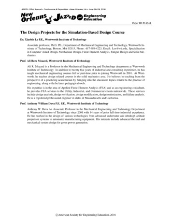
OvermoldingOvermolding is the injection molding process where one material (usually a TPE) is moldedonto a second material (typically a rigid plastic). If properly selected, the overmolded TPE willform a strong bond with the plastic that is maintained in the end-use environment. The useof primers or adhesives is no longer required to achieve an optimum bond between thetwo materials.Overmolding can be used to enhance many features of product designs, including:SafetyErgonomicsProduct Functionality Improved grip in dryand wet environments. Vibration damping. Increase in comfort level. Water resistant seal. Sound absorption. Electrical insulation.Overmolding Process SelectionA processor will weigh numerous factors when choosing the appropriate manufacturing methodfor the application. The most critical decision factors are production scale economics, local laborcosts, available equipment and the materials selected.Generally, insert molding is the process of choice when annual production volumes and local laborcosts are low. For higher volume production programs (over 250,000 units annually) or areas withincreased labor costs, multi-shot molding operations are the method of choice.With any overmolding application, the challenge is in achieving maximum adhesion between theTPE and the substrate. For some overmolding TPEs, there may be a significant difference in bondstrength between multi-shot and insert molding. Even if an excellent bond is achieved with two-shotmolding, the same material may have poor bond strength when insert molded. Thus, a completeunderstanding of the TPEs, engineering plastics, and associated details about molding these materialsis essential to produce high-quality finished products.Overmolding Process TypesTwo injection molding processes dominate the manufacture of overmolded products: insert moldingand multi-shot injection molding.Insert MoldingThe most widely used process is insertmolding, where a pre-molded insert isplaced into a mold and the TPE is shotdirectly over it (Figure 1). For molders,the advantage of insert molding is thatconventional single shot IM machinescan be used (new machineryexpenditures are not necessary), and thetooling costs associated with insertmolding are lower than with multi-shotprocessing.TPE OvermoldSubstrateFace Mounted Replaceable InsertMagnetized to Hold Metal InsertFigure 1. Spring-loaded insert for metal tolerances.Multiple Material MoldingMultiple material, also known as two-shot (or multi-shot), molding requires a special injectionmolding machine that is equipped with two or more barrels, allowing two (or more) materials tobe shot into the same mold during the same molding cycle.A molder will choose multi-shot molding to reduce cycle times, achieve superior part quality andreduce labor costs.23
OvermoldingOvermolding is the injection molding process where one material (usually a TPE) is moldedonto a second material (typically a rigid plastic). If properly selected, the overmolded TPE willform a strong bond with the plastic that is maintained in the end-use environment. The useof primers or adhesives is no longer required to achieve an optimum bond between thetwo materials.Overmolding can be used to enhance many features of product designs, including:SafetyErgonomicsProduct Functionality Improved grip in dryand wet environments. Vibration damping. Increase in comfort level. Water resistant seal. Sound absorption. Electrical insulation.Overmolding Process SelectionA processor will weigh numerous factors when choosing the appropriate manufacturing methodfor the application. The most critical decision factors are production scale economics, local laborcosts, available equipment and the materials selected.Generally, insert molding is the process of choice when annual production volumes and local laborcosts are low. For higher volume production programs (over 250,000 units annually) or areas withincreased labor costs, multi-shot molding operations are the method of choice.With any overmolding application, the challenge is in achieving maximum adhesion between theTPE and the substrate. For some overmolding TPEs, there may be a significant difference in bondstrength between multi-shot and insert molding. Even if an excellent bond is achieved with two-shotmolding, the same material may have poor bond strength when insert molded. Thus, a completeunderstanding of the TPEs, engineering plastics, and associated details about molding these materialsis essential to produce high-quality finished products.Overmolding Process TypesTwo injection molding processes dominate the manufacture of overmolded products: insert moldingand multi-shot injection molding.Insert MoldingThe most widely used process is insertmolding, where a pre-molded insert isplaced into a mold and the TPE is shotdirectly over it (Figure 1). For molders,the advantage of insert molding is thatconventional single shot IM machinescan be used (new machineryexpenditures are not necessary), and thetooling costs associated with insertmolding are lower than with multi-shotprocessing.TPE OvermoldSubstrateFace Mounted Replaceable InsertMagnetized to Hold Metal InsertFigure 1. Spring-loaded insert for metal tolerances.Multiple Material MoldingMultiple material, also known as two-shot (or multi-shot), molding requires a special injectionmolding machine that is equipped with two or more barrels, allowing two (or more) materials tobe shot into the same mold during the same molding cycle.A molder will choose multi-shot molding to reduce cycle times, achieve superior part quality andreduce labor costs.23
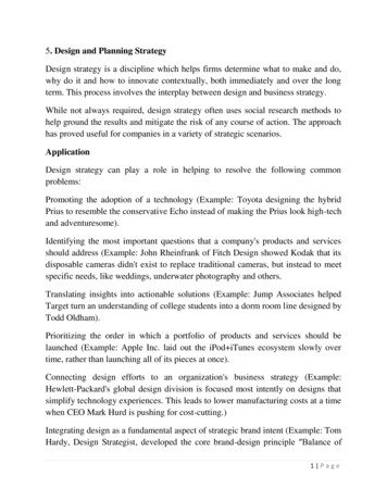
Material SelectionThe most common word used to describe a soft touch overmold is “feel” — but the termitself is very difficult to describe. When a designer wants the product to feel “grippy” or“squishy”, what exactly does this mean in terms of material properties?Basically, the “feel” of a soft touch overmold is dependent upon a combination of materialproperties (hardness, modulus, and coefficient of friction), texture and the TPE wall thickness.Thickness EffectsWhen choosing a soft touch TPE, designers usually ask for the softest material available. Whatthey do not know is that the soft durometer of a TPE adds little value to the concept of “cushion”when the thickness of the TPE is below a certain point (typically 0.040"). This means that thethinner the TPE overmold, the harder it will feel — the actual hardness effect is dependent onthe thickness of the TPE overmold. One way of getting around this issue is to incorporate multipleribs that are placed closely together to create the perception of thickness without using a large amountof material. This technique is used often in personal care grips.Adhesion RequirementsWhen selecting a TPE for an overmolding application, the substrate type should be considered.Not all GLS TPEs will bond to all types of substrates; for example, a Dynaflex TPE that bondsto polypropylene (PP) will not adhere to polycarbonate (PC).Avient offers a diverse product line of TPE compounds and alloys for overmolding onto a varietyof substrates. Most Dynaflex , Versaflex , Versalloy and OnFlex materials are suitable fortwo-shot or insert molding with a polypropylene (PP) as the insert or substrate.The Avient GLS Overmolding TPEs (Versaflex and Versollan ) are speciallyformulated to bond to a variety of thermoplastics, including: Polycarbonate (PC) Acrylonitrile Butadiene Styrene (ABS) PC/ABS Standard and Modified* Nylon 6, Nylon 6/6, Nylon 6,6,6Hardness vs. ModulusOne common myth in the TPE industry is that the durometer (or hardness) of a material is directlyrelated to its flexibility. This is not always true; for example, a 65 Shore A SEBS material ismuch more flexible than a 65 Shore A TPU. Instead of using Shore Hardness, a more suitablemeasure of flexibility is the flexural modulus, which measures a material’s resistance to bending.A higher flexural modulus typically means that a material will feel more stiff and unyielding.Coefficient of FrictionWhen two surfaces are dragged flat against each other, the resulting resistance is characterized asfriction. The coefficient of friction (COF) characterizes the degree of force required to move onesurface across another — either from a complete stop (static friction) or when the surface is alreadymoving (kinetic friction). Typically, TPEs are described as rubbery or “grippy” — Avient has thecapability to customize the COF according to the requirements of the application — from smoothand silky to extremely tacky.One area that product designers often misunderstand is the relationship between durometer andCOF. Most believe that the softer the TPE, the greater the COF — this is a very general statementand is not true in all cases. There are several GLS products in the 40 Shore A Hardness range thathave varying COFs. Copolyester Polystyrene (PS) High Impact Polystyrene (HIPS) PC/PETG Acetal (POM) Polyphenylene oxide (PPO) Alloys or blends of the above*Glass-filled, impact-modified, and/or heat-stabilized versions.For more information regarding specific overmolding TPEs and their corresponding substratematerials, please refer to the Avient's Thermoplastic Elastomers Product Selector Guide.For assistance in choosing the material with the optimum COF for an application, please contactyour Avient representative.45
Material SelectionThe most common word used to describe a soft touch overmold is “feel” — but the termitself is very difficult to describe. When a designer wants the product to feel “grippy” or“squishy”, what exactly does this mean in terms of material properties?Basically, the “feel” of a soft touch overmold is dependent upon a combination of materialproperties (hardness, modulus, and coefficient of friction), texture and the TPE wall thickness.Thickness EffectsWhen choosing a soft touch TPE, designers usually ask for the softest material available. Whatthey do not know is that the soft durometer of a TPE adds little value to the concept of “cushion”when the thickness of the TPE is below a certain point (typically 0.040"). This means that thethinner the TPE overmold, the harder it will feel — the actual hardness effect is dependent onthe thickness of the TPE overmold. One way of getting around this issue is to incorporate multipleribs that are placed closely together to create the perception of thickness without using a large amountof material. This technique is used often in personal care grips.Adhesion RequirementsWhen selecting a TPE for an overmolding application, the substrate type should be considered.Not all GLS TPEs will bond to all types of substrates; for example, a Dynaflex TPE that bonds topolypropylene (PP) will not adhere to polycarbonate (PC).Avient offers a diverse product line of TPE formulations and alloys for overmolding onto avariety of substrates. Most Dynaflex , Versaflex , Versalloy and OnFlex materials aresuitable for two-shot or insert molding with a polypropylene (PP) as the insert or substrate.Avient's GLS Overmolding TPEs (Versaflex and Versollan ) are speciallyformulated to bond to a variety of thermoplastics, including: Polycarbonate (PC) Acrylonitrile Butadiene Styrene (ABS) PC/ABS Standard and Modified* Nylon 6, Nylon 6/6, Nylon 6,6,6Hardness vs. ModulusOne common myth in the TPE industry is that the durometer (or hardness) of a material is directlyrelated to its flexibility. This is not always true; for example, a 65 Shore A SEBS material ismuch more flexible than a 65 Shore A TPU. Instead of using Shore Hardness, a more suitablemeasure of flexibility is the flexural modulus, which measures a material’s resistance to bending.A higher flexural modulus typically means that a material will feel more stiff and unyielding.Coefficient of FrictionWhen two surfaces are dragged flat against each other, the resulting resistance is characterized asfriction. The coefficient of friction (COF) characterizes the degree of force required to move onesurface across another — either from a complete stop (static friction) or when the surface is alreadymoving (kinetic friction). Typically, TPEs are described as rubbery or “grippy” — Avient has thecapability to customize the COF according to the requirements of the application — from smoothand silky to extremely tacky.One area that product designers often misunderstand is the relationship between durometer andCOF. Most believe that the softer the TPE, the greater the COF — this is a very general statementand is not true in all cases. There are several GLS products in the 40 Shore A Hardness range thathave varying COFs. Copolyester Polystyrene (PS) High Impact Polystyrene (HIPS) PC/PETG Acetal (POM) Polyphenylene oxide (PPO) Alloys or blends of the above*Glass-filled, impact-modified, and/or heat-stabilized versions.For more information regarding specific overmolding TPEs and their corresponding substratematerials, please refer to the Avient's Thermoplastic Elastomers Product Selector Guide.For assistance in choosing the material with the optimum COF for an application, please contactyour Avient representative.45
Part and Mold DesignPart Design Basics The wall thickness of the substrate and overmold should be as uniform as possibleto obtain the best molding cycle time. Wall thicknesses ranging from 0.060" to 0.120"(1.5 mm-3 mm) will ensure good bonding in most overmolding applications. If the part requires the use of thick TPE sections, they should be cored out to minimizeshrinkage problems, reduce the part weight and lower cycle time. Transitions between wall thickness should be gradual to reduce flow problems, such as backfills and gas traps. The use of radii (0.020" or 0.5 mm minimum) in sharp corners helps reduce localized stresses. Deep, unventable blind pockets or ribs should be avoided. Long draws should have a 3-5 draft per side to aid component ejection. Properly designed deep undercuts are possible with GLS TPEs ( 60 A Hardness) if:- The part does not have sharp corners.- An advancing core is used when the mold opens.- The elastomer is allowed to deflect as it is ejected. The TPE thickness should be less than or equal to the thickness of the substrate to preventwarpage; this is especially critical for long, flat geometries.Flow Length (L) and Wall Thickness (T)There are two main factors that affect the maximum achievable flow length for a specific TPE: theindividual TPE flow characteristics and the process conditions used in the overmolding process.The flow characteristics of a TPE can be quantified by performing a spiral flow test. Spiral flowtesting, which has been traditionally used for thermoplastics, provides the processor with a comparativeanalysis of a material’s ability to fill a part. The spiral flow lengths of various GLS product lines attwo injection speeds (3 in/sec and 5 in/sec) are summarized in Table 1. For applications with higherbond strength requirements, shorter flow lengths are advisable. Alternatively, mechanical interlocksare highly recommended.Table 1. Typical Flow lengths achievable with GLS TPEs*.Flow Length, inches (cm)SeriesInjection Velocity, 3 in/s (8 cm/s)Injection velocity, 5 in/s (13 cm/s)DynaflexTM D13-15 (33-38)18-20 (46-51)DynaflexTM G12-22 (30-56)18-30 (46-70)Versaflex9-16 (23-41)13-26 (33-66)VersalloyTM18-20 (46-51)30-32 (76-81)VersollanTM12-17 (30-43)19-22 (48-56)TM*Spiral flow tests performed using a 0.0625" (1.6 mm) thick, 0.375" (9.5 mm) wide channel at 400 F (204 C).6ShrinkageDue to the wide variety of chemistries of GLS overmolding TPEs, their shrinkage characteristicscan vary significantly. Table 2 summarizes general shrinkage ranges for the various GLS productfamilies. Typical shrinkage values for specific GLS products are located on the individual technicaldata sheet.It should be noted that these shrinkage values are guidelines only; the shrinkage of a material isextremely dependent on the material chosen, the part/mold design, and the processing conditionsused to mold the part. The shrinkage guidelines provided by Avient are based on a particularspecimen geometry (rectangle/plaque) and are determined using a specific type of injection moldingmachine. As a result, prototyping is highly recommended to assist in predicting the shrinkageeffects of a particular GLS TPE.The following process parameters may increase part shrinkage: Mold and melt temperatures that are too high – results in heat sinks due to shrinkage. Mold and melt temperatures that are too cold – leads to molded-in stresses that maycontribute to part warpage. Low pack pressures.Table 2. Typical shrinkage for GLS TPEs*.Typical Shrinkage, %SeriesFlow DirectionCross DirectionTM1.5- 2.10.7-1.3TM0.9- 2.10.5-1.0DynaflexVersalloy*These shrinkage values are a range that is representative of all of the TPE grades in a specific product family and should not beused as guidelines for part and mold design. Please refer to Product Data Sheets for specific shrinkage values for each individual grade.Shut-Off DesignsThere are two different types of shut-off designs with the purpose of minimizing flashing of theTPE or reducing the chance of peeling (delamination) of the TPE.To reduce the opportunity for peeling, the overmold should be designed inaccordance with the following guidelines: The surface of the TPE should be flush with the non-overmolded section of the substrate. The edge of the TPE should be at a deeper level than the surface of the non-overmoldedsection of the substrate. Do not design the TPE edge so that it is even with or over the edge of the part.7
Part and Mold DesignPart Design Basics The wall thickness of the substrate and overmold should be as uniform as possibleto obtain the best molding cycle time. Wall thicknesses ranging from 0.060" to 0.120"(1.5 mm-3 mm) will ensure good bonding in most overmolding applications. If the part requires the use of thick TPE sections, they should be cored out to minimizeshrinkage problems, reduce the part weight and lower cycle time. Transitions between wall thickness should be gradual to reduce flow problems, such as backfills and gas traps. The use of radii (0.020" or 0.5 mm minimum) in sharp corners helps reduce localized stresses. Deep, unventable blind pockets or ribs should be avoided. Long draws should have a 3-5 draft per side to aid component ejection. Properly designed deep undercuts are possible with GLS TPEs ( 60 A Hardness) if:- The part does not have sharp corners.- An advancing core is used when the mold opens.- The elastomer is allowed to deflect as it is ejected. The TPE thickness should be less than or equal to the thickness of the substrate to preventwarpage; this is especially critical for long, flat geometries.Flow Length (L) and Wall Thickness (T)There are two main factors that affect the maximum achievable flow length for a specific TPE: theindividual TPE flow characteristics and the process conditions used in the overmolding process.The flow characteristics of a TPE can be quantified by performing a spiral flow test. Spiral flowtesting, which has been traditionally used for thermoplastics, provides the processor with a comparativeanalysis of a material’s ability to fill a part. The spiral flow lengths of various GLS product lines attwo injection speeds (3 in/sec and 5 in/sec) are summarized in Table 1. For applications with higherbond strength requirements, shorter flow lengths are advisable. Alternatively, mechanical interlocksare highly recommended.Table 1. Typical Flow lengths achievable with GLS TPEs*.Flow Length, inches (cm)SeriesInjection Velocity, 3 in/s (8 cm/s)Injection velocity, 5 in/s (13 cm/s)DynaflexTM D13-15 (33-38)18-20 (46-51)DynaflexTM G12-22 (30-56)18-30 (46-70)Versaflex9-16 (23-41)13-26 (33-66)VersalloyTM18-20 (46-51)30-32 (76-81)VersollanTM12-17 (30-43)19-22 (48-56)TM*Spiral flow tests performed using a 0.0625" (1.6 mm) thick, 0.375" (9.5 mm) wide channel at 400 F (204 C).6ShrinkageDue to the wide variety of chemistries of GLS overmolding TPEs, their shrinkage characteristicscan vary significantly. Table 2 summarizes general shrinkage ranges for the various GLS productfamilies. Typical shrinkage values for specific GLS products are located on the individual technicaldata sheet.It should be noted that these shrinkage values are guidelines only; the shrinkage of a material isextremely dependent on the material chosen, the part/mold design, and the processing conditionsused to mold the part. The shrinkage guidelines provided by Avient are based on a particularspecimen geometry (rectangle/plaque) and are determined using a specific type of injection moldingmachine. As a result, prototyping is highly recommended to assist in predicting the shrinkageeffects of a particular GLS TPE.The following process parameters may increase part shrinkage: Mold and melt temperatures that are too high – results in heat sinks due to shrinkage. Mold and melt temperatures that are too cold – leads to molded-in stresses that maycontribute to part warpage. Low pack pressures.Table 2. Typical shrinkage for GLS TPEs*.Typical Shrinkage, %SeriesFlow DirectionCross DirectionTM1.5- 2.10.7-1.3TM0.9- 2.10.5-1.0DynaflexVersalloy*These shrinkage values are a range that is representative of all of the TPE grades in a specific product family and should not beused as guidelines for part and mold design. Please refer to Product Data Sheets for specific shrinkage values for each individual grade.Shut-Off DesignsThere are two different types of shut-off designs with the purpose of minimizing flashing of theTPE or reducing the chance of peeling (delamination) of the TPE.To reduce the opportunity for peeling, the overmold should be designed inaccordance with the following guidelines: The surface of the TPE should be flush with the non-overmolded section of the substrate. The edge of the TPE should be at a deeper level than the surface of the non-overmoldedsection of the substrate. Do not design the TPE edge so that it is even with or over the edge of the part.7
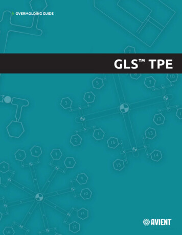
To reduce the probability of flashing the mold, the overmold should be designedwith the following guidelines: Provide a 0.015" – 0.030" (0.38 mm – 0.76 mm) deep groove on the substrate, along the edge ofthe TPE overmold (Figure 2). The steel should have positive shut-off in the groove. In addition,shrinkage of both the TPE and substrate should be considered. When metal or other non-compressible substrates are used, provide springs underneaththe steel sections shutting off on the substrate to prevent flashing due to a steel insert witha poor fit.TPESubstrateSubstrateTPEThe fundamental bond of GLSTPE over the rigid substrate canbe provided by a combination ofthree basic methods: Molecular adhesion. Mechanical design techniques. Mechanical interlocks.Figure 2. Examples of shut-off designs.Figure 3 illustrates three mechanicalinterlock design options that can beutilized to optimize finished componentbond strength.Utilizing texture on the TPE overmoldsurface is a good way to impart aunique surface feel to the productand minimize the appearance of surfaceFigure 3. Types of successful mechanical interlocks.defects. It should be emphasized thatcertain textures will lead to a perceived hardness that is higher (or lower) than the actualhardness of the TPE. As a result, the TPE surface texture should be taken into considerationduring the material selection phase of the product development process.8General Mold Design Considerations The viscosity of GLS overmolding TPEs is very shear dependent and this should be consideredwhen designing the molds and setting the molding process conditions. Start with small TPE injection gates to obtain best TPE fill with minimum cosmetic gate vestige.Large gates should be avoided. Gates should be located at the thickest TPE wall section. Thought should be given to proper component ejection from the tool to minimize markson the soft elastomer surface. It is critical that adequate cooling is provided to the TPE cavity through proper mold coolingtechniques to minimize cycle time. Flow ratios should not exceed 150: 1L/T as an absolute maximum for most overmoldingapplications.Mold ConstructionGLS overmolding TPEs are generally non-abrasive and non-corrosive. The choice of tool steel willdepend on the quantity and quality of parts to be produced, the longevity of mold required, andthe type of rigid substrate being used in the application. If a reinforced substrate material is used,high hardness abrasion resistant steel will be required. For high volume two-shot or insert moldedcomponent production, the initial expense of high quality injection mold tooling is a soundinvestment. P-20 steel is typically used for mold bases and ejector plate, while H-13 steel is used forcavity and core plates. For applications that require optimum cooling, beryllium copper coresare common.Most GLS materials replicate the mold surface fairly well. A polished mold is required to producea glossy surface or optimum clarity. To produce a part with the matte appearance of a thermosetrubber, a rougher mold surface is required. In general, an EDM finish will produce a good surfaceand good release from the mold. Vapor honing, sand or bead blasting and chemical etching mayalso be used to produce surfaces with varying degrees of gloss and appearance. To aid in release,the cavity or core may be coated with a release coating, such as PTFE impregnated nickel, after ithas been given a sand blast or EDM finish.9
To reduce the probability of flashing the mold, the overmold should be designedwith the following guidelines: Provide a 0.015" – 0.030" (0.38 mm – 0.76 mm) deep groove on the substrate, along the edge ofthe TPE overmold (Figure 2). The steel should have positive shut-off in the groove. In addition,shrinkage of both the TPE and substrate should be considered. When metal or other non-compressible substrates are used, provide springs underneaththe steel sections shutting off on the substrate to prevent flashing due to a steel insert witha poor fit.TPESubstrateSubstrateTPEThe fundamental bond of GLSTPE over the rigid substrate canbe provided by a combination ofthree basic methods: Molecular adhesion. Mechanical design techniques. Mechanical interlocks.Figure 2. Examples of shut-off designs.Figure 3 illustrates three mechanicalinterlock design options that can beutilized to optimize finished componentbond strength.Utilizing texture on the TPE overmoldsurface is a good way to impart aunique surface feel to the productand minimize the appearance of surfaceFigure 3. Types of successful mechanical interlocks.defects. It should be emphasized thatcertain textures will lead to a perceived hardness that is higher (or lower) than the actualhardness of the TPE. As a result, the TPE surface texture should be taken into considerationduring the material selection phas
wo injection molding processes dominate the manufacture of overmolded products: insert molding and multi-shot injection molding. Insert Molding The most widely used process is insert molding, where a pre-molded insert is placed into a mold and the TPE is shot directly over it (Figure 1). For molders,