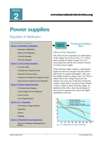
Transcription
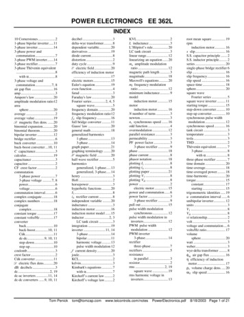
POWER ELECTRONICS EE 362LINDEX10 Cornerstones.21-phase bipolar inverter.113-phase inverter .143-phase power andcommutation.73-phase PWM inverter.143-phase rectifier .73-phase Thèvenin equivalent.8with α.83-phase voltage andcommutation.7, 8air gap flux .16amp.3Ampere's law .20amplitude modulation ratio12areasphere .20average .2average value.19B magnetic flux dens. .20binomial expansion.20binomial theorem.20bipolar inverter .12bridge rectifier .6buck converter .10buck-boost converter .10, 11C capacitance.3calculus.19capacitance .3capacitor .2CF crest factor .2commutation3-phase power .73-phase voltage .7, 8power.6voltage.6commutation interval.6complex conjugate.18complex numbers .18conjugatecomplex.18constant torque .17constant volts/Hz .17converterbuck.10buck-boost.10, 11Cúk.11dc-dc.9, 10, 11step-down .10step-up.10coulomb.3crest factor .2Cúk converter .11D electric flux dens.20dB decibels .3dc.2, 19dc-ac inverters .11, 14dc-dc converters .9, 10, 11Tom Penickdecibel .3delta-wye transformer.8dependent variable.20derivatives .19diode current.8distortion .2duty cycle .9E electric field .20efficiency of induction motor.17electric motors.15Euler's equation .19even function.4farad .3Faraday's law.20Fourier series.2, 4, 5square wave.5frequency domain.20frequency modulation ratio12fsl slip frequency .16full bridge converter .11Gauss' law .20general math .18generalized harmonics1-phase .133-phase .14graph paper.21graphing terminology .20H magnetic field .20half-wave rectifier .5harmonicsgeneralized, 1-phase.13generalized, 3-phase.14henry .3Hoft .2horsepower .3hyperbolic functions.20I1 .8iA rectifier current .8independent variable .20inductance .3induction motor .16induction motor model .15inductor .2, 3LC tank circuit .3integration .19inverter .11, 143-phase .14bipolar .11harmonic voltage.13pulse width modulation 12J current density .20joule.3KCL.2kelvin.3Kimbark's equations .7with α.7Kirchoff’s current law .2Kirchoff’s voltage law.2tom@tomzap.comKVL .2L inductance .3L’Hôpitol’s rule.20LC tank circuit .3linear range.12linearizing an equation .20ma amplitude modulationratio .12magnetic path length .3magnitude.18Maxwell's equations.20mf frequency modulationratio .12minimum inductance.9modelinduction motor.15motorinduction motor.16N number of turns .3newton.3ns synchronous speed .16odd function .4overmodulation .12parallel resistance .3permeability .3PF power factor.33-phase rectifier .9phase .18phase current .8phasor notation.18plotting I1 .8plotting iA .8plotting paper .21plotting V1 .8plotting Vdc .8power .2electric motor .15power and commutation.6power factor .33-phase rectifier .9pull out .15pulse width modulationsynchronous .12pulse width modulation ininverters.12PWM pulse widthmodulation .12PWM inverter3-phase.14rectifierthree-phase.7rectifiers .5resistancein parallel .3resistor.2rms .2, 19square wave .19rms harmonic voltage onics.pdfroot mean square . 19rpminduction motor. 16s slip. 16S.S. capacitor principle . 2S.S. inductor principle. 2series . 20single-phase bridge rectifier 6slip . 16slip frequency. 16slip speed . 16space-time . 18sphere. 20square waveFourier series . 5square wave inverter . 11starting torque . 15step-down converter. 10step-up converter. 10synchronous pulse widthmodulation . 12synchronous speed . 16tank circuit . 3temperature . 3tesla . 3THD . 2Thèvenin equivalent. 73-phase. 8with α . 8three-phase rectifier . 7time domain . 20time-average. 18time-averaged power. 18time-harmonic . 20torque . 15constant. 17starting . 15trigonometric identities . 19u commutation interval . 6unibipolar inverter. 12units . 3V1 . 8Vdc . 8vi relationship. 2volt . 3voltage and commutation . 6volts/Hz ratio. 17volumesphere. 20watt . 3weber. 3wye-delta transformer . 8φag air gap flux . 16η efficiency of inductionmotor. 17ρν volume charge dens. . 20ωsl slip speed . 168/18/2003 Page 1 of 21
10 CORNERSTONES OF POWERELECTRONICS - Hoft8. S.S. INDUCTOR PRINCIPLEUnder steady state conditions, the average voltageacross an inductor is zero.1. KVLKirchoff’s Voltage Law. The sum of the changes involtage around a circuit loop is equal to zero. This istrue in both the instantaneous and average (integrateover one cycle) sense.2. KCLKirchoff’s Current Law. The current entering a node isequal to the current leaving the node. This is also truein both the instantaneous and average (integrate overone cycle) sense.9. S.S. CAPACITOR PRINCIPLEUnder steady state conditions, the average currentthrough a capacitor is zero.10. FOURIER SERIESIn the 1820s, Fourier came out with a 1-page paper onhis Fourier series. A periodic function may bedescribed as an infinite sum of sines and cosines. v ( t ) Vavg ak cos ( k ω0t ) bk sin ( k ω0t ) 3. vi RESISTORk 1The voltage to current relationship in a resistor.v irSee p4.DISTORTION [%]4. vi CAPACITORDistortion is the degree to which a signal differs fromits fundamental frequency.The voltage to current relationship in a capacitor.i CdvdtTHD RMS value of harmonics for k 1RMS value of fundamental frequency k 15. vi INDUCTOR%THD 100The voltage to current relationship in a inductor.VdisVrms122Vrms Vrms1 100Vrms1div LdtUse the polar form of the Fourier Series, see p4.6. AVERAGE (DC) AND RMSAverage and dc will be synonymous in this class, butare not the same as rms.vavg 1 t0 Tv ( t ) dtT t0vrms 1 t0 T 2v ( t ) dtT t07. POWERWe are concerned with both instantaneous andaverage power. As with rms values, power is relatedto heating.Pavg 1T t0 Tt0p ( t ) dtVdis rms voltage distortion [V]Vrms1 fundamental frequency rms voltage [V]Vrms rms voltage [V]THD Total Harmonic Distortion [V]CREST FACTOR [no units]The crest factor quantifies the smoothness of thewaveform and is related to the weight of its impact oncomponents. For DC and a square wave the crestfactor is 1, for a sine wave, it is 1.414. A large crestfactor means the wave is not as efficient at deliveringenergy.p (t ) v (t ) i (t )CF VpeakVrmsp(t) instantaneous power [W]Tom Electronics.pdf8/18/2003 Page 2 of 21
C CAPACITANCE [F]PF POWER FACTOR [no units]The power factor is the ratio of true power (the powerconsumed, ignoring the reactive factor) to apparentpower (the total power consumed). Also, the powerfactor is the cosine of the angle by which the currentlags the voltage (assuming an inductive load).PF cos ( θv θi )i( t ) I f ( I o I f )e t / τ v C-v ( t ) V f (Vo V f )e t / τwhereτ RCic ( t ) C dvdtVc ( t ) R1 ti dτ VoC 0 L INDUCTANCE [H]DECIBELS [dB]A log based unit of energy that makes it easier todescribe exponential losses, etc. The decibel means10 bels, a unit named after Bell Laboratories.voltage or currentL 20 logreference voltage or currenti( t ) I f ( I o I f )e t / τv ( t ) V f (Vo V f )e t / τwhereτ L/ Rv L ( t ) L dtdipowerL 10 logreference power v L-I L (t ) R1 tv dτ I oL 0of an inductor: L .4πµN 2 AeI e 10L inductance [H]µ permeability [H/cm]N number of turnsAe core cross section [cm2]Ie core magnetic path length [cm]UNITS, electricalI (current in amps) q W J N ·m V ·Cs V V ·s V ·ssJN·mW ·sq (charge in coulombs) I ·s V ·C VVVLC TANK CIRCUITResonant frequency:22C (capacitance in farads) q q q J I ·sVJN ·m V 2 VH (inductance in henrys) V ·s (note that H·F s 2 )IC2J (energy in joules) N ·m V ·q W ·s I ·V ·s C ·V 2 qCJq·VW·skg·mN (force in newtons) 2mmmsWbV·s H · IT (magnetic flux density in teslas) 2 22mmmV (electric potential in volts) W JJ W ·s N ·m q Iq I ·sqqCLf 12π LCPARALLEL RESISTANCEI never can remember theformula for two resistances inparallel. I just do it the hardway.R1 R2 R1 R2R1 R2W (power in watts) J N ·m q·VC ·V 21 V ·I HPssss746Wb (magnetic flux in webers) H ·I V ·s JITemperature: [ C or K] 0 C 273.15Kwhere s is secondsTom Electronics.pdf8/18/2003 Page 3 of 21
FOURIER SERIESFOURIER SERIES and SymmetryThe Fourier Series is a method of describing acomplex periodic function in terms of the frequenciesand amplitudes of its fundamental and harmonicfrequencies.Let f ( t ) f ( t T ) any periodic signalwhere T When the function f(t) is symmetric, certain shortcutscan be taken.When f(t) is an even function, i.e.f(t) f(-t), bk is zero. The Fourierseries becomes: f ( t ) Favg ak cos ( k ω0t ) 2π the period.ωk 1If there is also half-wavesymmetry, then:f (t)4 T /2f ( t ) cos nωt dtT 0ak 01T2TWhen f(t) is an odd function, i.e.f(t) -f(-t), ak is zero. The Fourierseries becomes:t Thenf ( t ) Favg ak cos ( k ω0t ) bk sin ( k ω0t ) k 1ω0 the fundamental frequency (k 1) in radians/sec.kω0 the harmonic frequencies (k 2,3,4 ) in radians/sec.k denotes the fundamental (k 1) or harmonic frequencies(k 2,3,4 ), not the wave number or propagationconstantFavg the average value of f(t), or the DC offsetFavg 1T t0 Tt0f ( t ) dtak twice the average value of f(t)cos(kω0t)ak 2 t0 Tf ( t ) cos k ωt dtT t0bk twice the average value of f(t)sin(kω0t)bk 2T t0 Tt0f ( t ) Favg bk sin ( k ω0t ) k 1If there is also half-wavesymmetry, then:bk 4T T /20f ( t ) sin nωt dtWhen f(t) has half-wavesymmetry, i.e. f(t) -f(t T/2), thereare only odd harmonics.k 1, 3, 5, 4 t0 T / 2f ( t ) cos nωt dtT t04 t0 T / 2bk f ( t ) sin nωt dtT t0ak f ( t ) sin k ωt dtT2FOURIER SERIES, Polar Formt0 an arbitrary time f ( t ) Favg Fk sin ( k ω0t δk ) k 1whereFk ak2 bk2,δk tan 1 bkak2 t0 Tf ( t ) cos nωt dtT t02 t0 Tbk f ( t ) sin nωt dtT t0ak Tom Electronics.pdf8/18/2003 Page 4 of 21
FOURIER SERIES OF A SQUARE WAVESINGLE-PHASE RECTIFIERSA 50% duty cycle squa
Tom Penick tom@tomzap.com www.teicontrols.com/notes PowerElectronics.pdf 8/18/2003 Page 1 of 21 POWER ELECTRONICS EE 362L INDEX
